Note: Descriptions are shown in the official language in which they were submitted.
1 3267 58
--1
Description
Process of Desulfurization
Field of the Invention
This invention relates to desulfurization and is more
particularly concerned with desulfurization in the presence of
limestone wherein gypsum is recovered as a by-product.
S Background of the Invention
Air pollution is a very serious and urgent inter-
national problem. The sources Oe air pollution are primarily
the products of combustion and are numerous and widespread.
Many of the air pollutants are in the foem of sulfur-
bearing flue gases discharged by fossil-fuel-burning electrical
power generating plants or other industries. While the precise
impact of thesc pollutants on the cnvironment is still a subject
of speculation, there nonethelcss is considered to ~e a possible
negative effcct. Yet, under ~oreseeablc circumstances, it will
lS will bc necessary to burn more and more fuel to meet the demands
of a rapidly growing population rcquiring for each person ~ver-
morc heating comfort ~nd power, and the fuel which will gencrally
be used will not contain much less sulfur, but will likely con-
tain more sulfur.
Thus, sulfur oxidcs, principally presont as sulfue
dioxidc, are ~ound in the waste gascs discharged from many
mctal rcfining and chemical plants, and in the flue gascs
from powor platlts generating electricity by thc combustion oE
ossii Euels. In ad~ition, sulfue-con~aining gascs, notably
sulfur dioxi~c, may ba eormed in the ~artial combustion or
~ 3~67 58
gasification of sulfur-containing fuels, such as coal or petro-
leum residua. The control of air pollution resulting from the
discharge of sulfur dioxide into the atmosphere has thus become
increasingly urgent.
The most common flue gas desulfurization ~FGD) process
is known as the "wet process~. In that process the s~lfur
dioxide-containing flue gas is scrubbed with a slurry containing,
e.g., limestone. The scrubbing takes place, for example, in an
absorption tower in which the gas flow is countercurrent to and
in intimate contact with a stream of slurry. The slurry may
flow over packing or trays, or be sprayed into an open section
of the tower. The spent slurry product of this FGD process con-
tains both calcium sulfite and calcium sulfate. It has been
found to be advantageous to convert the calcium sulfite in the
product to calcium sulfate by bubbling air or other o~ygen-
containing gas through the slurry.
Gypsum has many advantages, such that it is much in
demand, essentially harmless, incombustible, and chemically
stable, and it can be disposed of as waste material in land
reclamation without the danger of secondary public nuisance.
Moreover, limestono can be uscd as a neutralizing agent in
desulfurization with gypsum as a by-product. The latter is
not only exceptionally cheap as compared with other neutralizing
agents, but it is also readily available in a relatively long-
lastin~ stablc form.
~3- 1 326758
One system for the desulfurization o flue gases by
means of a limestone-containing scrubbing liquid involves a
double loop or circuit or the liquid streams being employed,
such as shown in Biedell et al, U.S. patent 4,351,804. In
that system, the gas to be treated first enters a ~quencher~
and then passes to an ~absorber", and the two liquid loops or
circuits are each connected to one of these two units and to
each other. A slurry containing limestone and gypsum solids
fed to the quencher is contacted with the flue gas being treated
and, after contact, accumulates at the bottom o the quencher,
and air i9 introducPd into the liquid accumulated in the guencher
to oxidize the calcium sulfite which has been ormed from the
reaction between S02 and limestone, to calcium sulfate ~gypsum).
Limestono is fed to the absorber feed tank from which
a slurry containing limestone, calcium sulfite and calcium
sulfate is fed to the absorber for contact with the flue gas.
This slurry is recirculated to the feed tank. A portion o the
slurry in the absorber feed tank overflows to the quencher and
; a portion is sent to a set of hydroclones. The hydroclones
separato the solids from the liquid in the slurry and the con-
centrated solids are discharged directly to the quencher. The
dilute stream from the hydroclones is returned to the absorber
; feed tank. The purpose of this step is to control the sus-
pendcd solids concontration in thc absorber eod tank slurry.
O~jec~ivcs of a forced oxidizcd limostono dosulfuriza-
tion procoss aro ~o maximize tAho purity oE tho 9yp5Um producod
~4~ 1 3? 67 58
since the commercial attractivencss of the gypsum is a function
of its purity, and to produce a low degree of sulfur gas
~e~pressed as SO2) in the flue gas effluent at a reasonable
gas flow.
S While the above-mentioned double loop system for
; desulfurization utilizing limestone as a raagent is generallyeffective, difficulty has been experienced in meeting the
stated objectives of a high degree of desulfuri~ation with
simultaneous production of gypsum of high purity. Difficulty
has also been experienced by reason of gypsum scale formation
in the treating apparatus associated with the absorber. The
chemical scale which grows on the absorber packing eventually
accumulates until it obstructs the normal path of the flue gas
through the absorber. At that time, costly maintenance must
be performed on the absorber to remove the scale.
Objects of the Invention
; It is, accordingly, an object o this invention to
provi~e an improved process for flue gas desulfurization.
It is another object of the invention to provide an
improved w~t process for desulfurization utilizing limestone
as a rcagent.
lt is a ~urther object oE the invention to provide
an lmprovcd dcsul~urization pcocoss which will product high
quality gypsum as a by-product.
~5~ 1 326758
It is a still further object of the invention to
provide an Lmproved desulfurization process wherein scaling
and deposition of solids within the absorber packing are
suppressed.
Summary of the Invention
These and other objects are achieved in accordance
with the invention by effecting, in a double loop desulfuriza-
tion system employing limestone as a reagent, oxidation of
sulfite to sulfate not only in the quencher but in the absorber
feed tank IAFT) as well, and by the direct addition of limestone
to the quencher as well as to the absorber feed tank~
Brief Description of the Drawinqs
The invention will now be described in more detail by
refesence to the accompanying drawings, wherein:
lS FIGURE 1 is a diagrammatic flow shect of the pertinent
portion of the prior art double loop dcsulfurization system; and
FIGURE 2 is a similar flow sheet of this portion of
the double loop desulfurization system, embodying features of
the prescnt inven~ion.
Description of the Preferred Embodiments
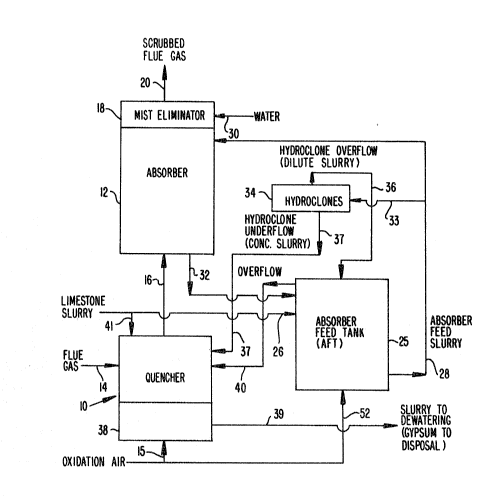
: Referrin~ now to the drawings, and particularly to
Figure 1, the prior double loop desul~urization system illustra
ted cmbodics a quencher 10, and an absorber 12. The flue gas to
be trcatcd is fed to quencher 10 through line 14 and in the
quoncher 10 it is brought into contact with qucnclling liquid
co~prising a slurry of limestono and calcium sul~ato, which is
1 326758
--6--
advantageously distributed through headers (not shown) and the
slurry after distribution and contact with the flue gas accumu-
lates in the bottom (sump) of quencher 10, suitably provided
with an agitator (not shown~.
In the quencher 10, contact of the limestone ~CaCO3)
with the sulfur gases (SO2) that were absorbed from the flue gas
and that are now present in the liquid phase of the slurry as
dissolved sulfite species, produces calcium sulfite. The calcium
sulfite still in the liquid is converted to calcium sulfate
(gypsum~ by air oxidation. -A line 15 is provided for the intro-
; duction of air into the accumulated slurry in the quencher sump
for this purpose. In addition, calcium sulfite enters the
quencher from the absorber feed tank via lines 37 and 40. This
is because most of the S02 removed from the flue gas is done so
in the absorber soction. Most of this absorbed SO2 precipitates
as solid calcium sulfite in the absorber feed tank with a smaller
fraction being naturally oxidized by the oxygen in the flue gas
to produce calcium sulfate which also precipitates in the ab-
sorber feed tank. Therefore, since the purpose of the oxidation
step in the quencher is to convert all sulfite to sulate, and
since tho rcaction between oxygen and sulfite occurs in the
; liquid phase only, this calcium sulfite must dissolve fir-~t,
react with oxycten from the air introduced Into the qucncher, then
precipitate as calcium sulfate.
The sulfite dissolution rate ls slow at slurry p~s
abovQ about 5.0; therofore, thc quenchcr must opcrate at a pll oE
at most 5.0 to promotc good convcrsion of sulfite to sul~ate
-7- 1 326758
within the relatively short amount of time available in thc
quencher. As indicated below, the pH in the quencher is main-
tained at 4.5 to 5.
The flue gas treated in quencher 10 then flo~s upward-
ly (line 16~ through a separator which isolates the quencher
slurry from the absorber feed tank slurry to absorber 12, where
the remainder o the S02 removal from the flue gas occurs. This
is accomplished by contacting the flue gas with a slurry contain-
ing limestone, calcium sulfite and calcium sulfate in a sl~rry-
spray section of the absorber similar to that used in the
quencher. Immediately above this spray section, the flue gas
enters the ~packed section~ of the absorber which contains a
corrugated-type plastic fill material which promotes good con-
tacting between absorber feed tank slurry, a stream of which is
continuously sprayed onto the packing, and the flue gas. The
improved contacting of the gas and slurry increases the SO2
removed from the flue gas. After the packing section, the flue
gas passes through a mist eliminator 18 and eventually leaves
the system through outlet line 20.
In the drawings, the systems for supplying and remov-
ing fluids from the quencher and absorb~r arc shown in abbre-
viated fashion in order to acilitate the doscrlption of the
invcntion and its relationship to the prior ar~. Thus, referring
again to Figure 1, the ~ain COmpOnQnt of ~he Eluid-flow loops
is thQ absorber fced tank 25 into which the desulfurizatlon
reagcnt, limestono, is fcd. The limestone is supplicd to tank 2S
-~- 1 326758
to form an aqueous slurry in the feed tank 25 via line 26 wherein
it is mixed with the calcium sulfite and ealeium sulate solids
formed from the reaction of SO2 and limestone. The slurry leaves
absorber feed tank 25 via line 28 which leads to absorber 12
S which contains headers (not shown) for distribution of the slurry
both in the spray section and in the paeked section for eontaet
with the flue gas passing through absorber 12.
8efore eventually leaving the absorber through outlet
line 20, the gas passes through mist eliminator 18, which may
ld comprise one or more units, and mist eliminator 18 is supplied
ith wash water entering through line 30 to elean it of solids
which accumulate on its surfaces. A line 32 earries spent
absorber feed slurry from the absorber tower, after contact with
the flue gas, back to the absorber feed tank.
Returning to the absorber tank circuit or loop, some
of the slurry in line 28 is diverted into line 33 and this
line 33 carries the diverted slurry ~typieally 10~ solids by
weight~ to one or more hydroclones 34 whieh separate by centri-
fugal forces the liquid phase from the solid phase of the slurry,
resulting in an overflow dilute slurry ~typically 6~ solids by
weight) and an underflow concentrated slurry ~typically 30%
solids by weight). The overflow dilute slurry is returned to
the absorber feed tank 25 via line 36 and the underflow eoncen-
trated sluery is supplied to the quencher 10 via line 37 for
desulfurizing concac~ with the flue gas. Most oE the limestone
Eor reaction with the S~2 removed in the quencher section is
9 1 326758
contained in this st~eam. The purpose of the hydroclones is to
provide a means to control the solids ~oncentration of the
absorber feed slurry. By removing a high suspended solids
concentration stream from the slurry in the absorber ~eed tank,
the building o~ solids in this tank can be controlled.
A smaller amount of limestone enters the quencher
from an overflow line on the absorber feed tank. This line
maintains the absorber feed tank at a constant level by gravity
draining slurry from the top of the tank when ~he level reaches
this point. The material balance around this tank is such
that water and solids continuously accumulate in this tank and
thus some slurry is always overflowing to the quencher vi~a line
40 since the volume leaving the tank via line 37 is less than
the amount fed to the tank. The accumulated liquid 38 in the
sump of quencher 10 is removed from the quencher sump via line
39 and is subsequently dewatered to recover the gypsum which
has been formed.
Calcium sulf ite solids are present in the absorber
eed tank 25 as a result of the flow through line 3~ leading
from the absorber 12 where contact between the sul~ur oxide in
the flue gas and the limestone has occurred. It also typically
contains some calcium sulfate solids which are formed in the
absorber 12 by reaction of oxygen in the flue gas with the
calcium sulfite formed as the limestone in the slurry entering
through line 25 reacts with thc sulfur gases in the 1ue gas and
is containcd in the ~low to the absorber feed tank 25 via line
32.
-lo- 1 326758
In accordance with this invention basic improvements
are made in the above-described desulfuri~ation system and
process, which bring about surprising and unexpected re~ults in
t~rms of increased desulfurization, the production of gypsum of
high purity, and the simultaneous suppression of chemical scaling
problems in the absorber.
Thus, referring now to Figure 2, the system shown in
Figure 1 is reproduced, but line 26, through which a slurry of
limestone is supplied to absorber feed tank 25, is provided wi~h
a branch or diversion line 41 through which limestone is fed
directly to the quencher. It has been discovered, through
extended operating experience with the prior art, that periodic-
ally the amount o limestone fed to the quencher was inadequate
to react with the amount of SO2 absorbed in this part of the
absorber. The reason for the inadequate feed o limestone to
the quencher is due to the indirect method of feed Iimestone to
the quencher. In the prior art, limestone must first pass
through the absorber fQed tank bcfore it reaches the quencher.
The volume o~ the absorber eed tank is very large rela~ive to
the volume of limestone fed to this tank. It therefore takes an
inordinate amount of time for a change in the limestone feed
rate to the abscrber eed tank to result in a change in the
amount of limcstone being fed to the quencher.
l~hen the amount of limestone fcd to the quencher is
too low to rc.lut with thc absorbcd SO " thc pH of the quenchcr
slurry declinofi. This drop of pH rcsults in a reduction in
1 32675~
the SO2 removal efficiency of the quencher and an overall drop
in the absorber SO2 removal efficisncy until the pH can be
raised. By feeding limestone directly to the guencher, the p~l
of the quencher slurry can be more closely regulated and the low
S pH excursions avoided. As a result, the time average SO2 ~emoval
of the absorber is increased. For proper operation, therefore,
the pH in the quencher is maintained at 4.5 to 5.
In addition, air for oxidizing sulfite to s~lfate
is introduced not only into the quencher 10 through line 15, but
air is also introduced into absorber feed tank 25 through line
52 for contact with the slurry in this tank. Typically such air
is introduced beneath the slurry surface through sparging headers.
It has been surprisingly discovered that, in accord-
ance with the invention, conversion of the sulfite to sulfate
in the absorber feod tank 25 by reason of the introduction of
air through line 52 results in the presence in the slurry of a
much larger crystal - the calcium s~lf~te dihydrate crystal
compared to the calcium sul~ite hemihydrate crystal. Complete
conversion of sulfite to sulfate has been demonstrated through
extensive testing. The particle si~e of the calcium sul~ate is
as large and larger than that o~ the limestone in the absorber
feed tank 25. As a result, the calcium sulfate has more of a
tcndency to exit the underflow of the absorber fced tank hydro-
cloncs 34. This reducos uncontrolled quantities of limestono
boing fed to the qucncher lO through line 37 and, in effoct,
~sllort-circuiting ~ the quencher through the hydrocloncs 3q,
-12- 132675~
which has led to too high a pH in the quencher for good sulfite
oxidation and limestone utilization, causing a reduction in
gypsum quality.
Table 1 shows a comparison o~ particle size measure-
ments made on the absorber feed tank ~AFT) sul~ur solids, theAFT hydroclone overflow sulfur solids and the AFT hydroclone
underflow sulfur solids. The results show a significant
increase in the average particle diameter of the sulfur solids
due to oxidation. The prior art AFT sulfur solids average 24
microns in diameter, whereas the improved process AFT sulfur
solids average about 40 microns. This compares to the average
particle diameter of the limestone in the AFT of about 20
microns if a "fine" limestone is fed (nominally 90 percent of
the limestone less than 74 microns). When a coarse limestone
lS (70 percent less than 74 microns) is fed to the AF~, the
average limestonc particle diametcr in the AFT has been measurcd
to be 42 microns.
Analysis of the AFT solids indicatcs that ~sscntially
complete conversion of the calcium sulfite to calcium sulate is
~ 20 accomplished by sparging the AFT with air. The difeerence in
; particle size for the AFT sulfur solids is due to the different
shape of the calcium sulfite and calcium sulfate crystals. The
beneficia~ efect that this has on the performance o~ the AFT
hydroclones can bc sccn by examining Table 2, which prescnts
thc rcslllts oE actual analyscs ~rom opcrating absor~ors oE thc
limcstonc in the streams into and out o the AFT hydroclones
opcrating with and without oxidation in thc AFT.
-13- 1 3 2 6 7 5 8
The limestone concentration in the AFT hydroclone
underflow i5 significantly greater than that in the AFT slurry
for the prior art system, both with a coarse and with a fine
limestone fed to the AFT t330 percent and 200 percent greater,
S respectively). The limestone concentration in th~ AFT hydro-
clone underflow is virtually the same as that in the AFT slurry
for the improved process, however, the eEfect of the particle
size o~ the limestone fed to the AFT also is diminished. There
is only a slight improvement in CaCO3 m~gnification (defined as
the ratio of CaCO3 in the hydroclone underflow to the CaCO3 in
the AFT) in the case of fine limestone compared to the coarse
limestone for the improved process. Therefore, slight varia-
; tions in limestone particle size which often occur in these
processes will have little effect on the overall performance of
tho FGD system. In fact, the improved process would allow
satisfactory operation with coarse limestone which is signifi-
cantly less costly to prepare than a fine limestone.
Tha direct and beneficial result o~ operation with
less limestone in the AFT hydroclone underflow is that the
quencher can be controlled at a pH which is beneficial for
producing a high quality gypsum. Furthermore, this can be
acco~plished with the absorber operating at a high level of
S2 removal eficiency. Table 3 pcesents the results of
testing an absorber with and without AFT oxidation and direct
fcod of limestone to the qu~ncller. Thc results show a dramatic
increaso in tho quality of the product solids from tho quoncher,
-14- 1 326758
measured as the calcium sulfate dihydrate or gypsum fraction.
Without AFT oxidation and direct feed of limestone to the
quencher, the gypsum fraction in the product solids is 69
percent, which makes it unacceptable as a raw material for any
S further use, such as wallboard manufacture.
Moreover, in the prior art system, it has been found
that the packing in the absorber 12 tends to become subject to
scaling and plugging. It is believed ~hat this has occurred as
a result of the unwanted deposition of the gypsum which forms
in the absorber due to the reaction of sulfite and the oxygen
in the flue gas as discussed above. A surprising effect of the
improvements of this invention is that, as a result o the
conversion of sulfite to sulfate ~gypsum) in the absorber
feed tank 2S by the reason of the oxidation caused by the intro-
duction of air in the tank, calcium sulfate becomes the predomin-
ate solid species in thc slurry. The presence of the large
amount of calcium sulfate crystal surface area provides numerous
sitss for precipitation o the calcium sulfate fonmed in the
packing due to sulEite oxidation there. The gypsum thus formed
preferentially grows on the existing gypsum crystals rather than
on the surface of the packing. In any case, by operating in
accordance with the invention, e.9., by providing precipitation
sites or the calcium sulfate formed in the packing, the rate of
scalo formation and plugging is significantly rcduccd. The
2S av~a~e nu~ber of operatinJ days from the time an absorbcr
towcr is placcd into scrvice with ncw packing until tho time
1 3 2 6 7
-15-
it must be removed from service due to pluggage of the packing
is about 55 days for the original design based on extensive
operating experience. Oxidation in the absorber feed tank
has allowed this period to be increased to at least 120 days,
thereby reducing by more than 50 percent the amount of packing
which would be considered on an annual basis.
While the present invention has been particularly set
forth in terms of specific embodiments thereof, it will be
understood in view of the instant disclosure, that numerous
variations upon the invention yet reside within the scope of the
present teaching. Accordingly the invention is to be broadly
construed, and limited only by the scope and spirit of the claims
,,
now appended hereto.
-16- 1 326758
Table 1
AVERAGE CRYSTAL DIAMETER FOR SULFUR SOLIDS IN AFT,
AFT HYDROCLONE OVERFLOW AND AFT HYDROCLONE UNDERFLOW SLURRY
-
. ,
Average Particle Diameter, microns
AFT HydrocloneHydroclone
OverflowUnderflow
-
Prior Art 24 21 30
. Improved Process 40 25 49
::
-17- 1 3 2 6 7 S 8
Table 2
EFFECT OF AFT OXIDATION ON CaC03 MAGNIFICATION
IN THE HYDROCLONE UNDERFLOW
CaC03
A~T Hydroclone Magnification
CaC03,Wt% Underflow in Hydroclone
CaC03,Wt% Underflow, %
Prior Art
Coarse Limestone 9~3 31.0 330
Fed to AFT
Fine Limestone 11.0 22.0 200
Fed to AFT
Improved Process
Coarse Limestone
Fed to AFT lS.S 17.0 110
lS Fine Limestone 16.2 14.6 90
.
18 1 326758
Table 3
EFFECT OF AFT OXIDATION ON ABSORBER S2 REMOVAL
EFFICIENCY AND PRODUCT GYPSUM PURITY
Absorber SO2 Gypsum Fraction
Removal In Product
Efficiencv, ~ Solids, % CaS04 2H~O
Prior Art 95 69
Improved Process 9~ 94