Note: Descriptions are shown in the official language in which they were submitted.
1326963
DISCLOSURE
This invention relates to brick ties of the kind which
are used for anchoring a brick wall to a vertical channel-
shaped member to which a dry wall has already been secured.
It is common practice to provide buildings, for example
light industrial buildings, with a brick exterior wall. Since
such a wall may have con6iderable length and/or height, it is
necessary to anchor the wall at intervals to other structure
of the building. Such buildings usually also have a series of
vertical channel-shaped member~ (known as 6tuds) to which
interior walls can be secured. It is also usual to secure a
dry wall, for example exterior gypboard sheathing, preferably
with the addition of separate vapour barrier sheet material, to
the exterior of the channel-shaped members so that the dry wall
lies between the channel-shaped members and the brick wall.
In the con6truction of such buildings, the brick wall is
built by brick layers, while other tradesmen construct other
parts of the building before the brick wall is built. The
brick ties are secured to the channel-shaped members at
predetermined positions by a person of the appropriate trade 80
that the brick ties project through the dry wall to enable a
bricklayer to subsequently construct the exterior brick wall
and cause the brick ties to be embedded in mortar between
adjacent bricks.
Typical known arrangements are shown in U.S. patent
4,021,990 (Schwalberg) issued May 10, 1977, and U.S. patent
4,596,102 (Catani) issued June 24, 1986. In such prior art,
~ ~.
1326963
the brick tie has a first part attached to a vertical channel-
shaped member by screws which pass through the dry wall into
the channel-shaped member, and a second part which is attached
to the first part and i~ embedded in the brick wall. The
second part is capable of adjustment relative to the first part
to enable the bricklayer to properly position the second part
between adjacent bricks. However, the attachment of the first
parts of the brick ties to the channel-shaped members have to
be carried out by a tradesman other than a bricklayer. This
is inconvenient, particularly since such attachments have to be
effected from the exterior of the building, i.e. on the
exteriox side of the dry wall. It is also difficult for the
per60n concerned to correctly position the brick tie.
It is therefore an object of the invention to provide an
improved brick tie which substantially overcomes the
difficulties of such prior art brick ties.
According to the present invention, a brick tie
compri~es a first part having a body portion insertable into
the channel-shaped member through the open side thereof and
wedgeable therein, and a second part attachable to the first
part and positionable between adjacent bricks as the wall is
being constructed, with one of said parts passing through the
dry wall.
The first part of the brick tie, in accordance with the
invention, can conseguently be secured to a channel-shaped
member from within the building by a person of the appropriate
trade. The desired position can be readily determined by
- . : . ~ , . , , . , ~
1326963
conventional measuring equipment, such as the laser measuring
equipment now available in the art. The first part may be
caused to project through the dry wall for the outside
attachment of the second part thereto by a brick layer during
construction of the brick wall, or the second part may be
attached to the first part adjacent to the channel-shaped
member and cause to pass through the dry wall to the outside
for incorporation in the brick wall as it is being constructed
by the brick layer.
The first part of the bric~ tie may be of sheet
material, with the body portion having a main web-like member
which extends horizontally across the channel-shaped member
when wedged therein, the first flange extending downwardly from
an end of the web-like member and a second flange extending
upwardly from an opposite end of the web-like member. The
said first and second flanges engage front and rear walls of
the channel-shaped member when the first part is wedged
therein.
The body portion of the first part of the brick tie may
also have a flange extending upwardly from the side of the main
web-like member and fourth flange extending downwardly from
said side, the third and fourth flanges engaging a side wall of
the channel-shaped member opposite the open side when the first
part is wedged therein.
The first part of the brick tie may have a portion
projecting from the body portion and positioned to pass through
the dry wall to an exterior side thereof when the body portion
1326963
is wedged in a channel-shaped member, with said projecting
portion having means to enable the second part to be secured
thereto on the exterior side of the dry wall.
The means on the projecting portion of the first part of
the brick tie to enable the second part to be secured thereto
may comprise an aperture therein, with the second part
comprising a shaped rod-like member passable through the
aperture so as to be secured to the first part. The aperture
in the projecting portion may comprise a slot which is vertical
when the body portion iæ wedged in a vertical channel-shaped
member, with the second part being vertically moveable in the
slot.
The first part of the brick tie may alternatively have a
portion projecting from the body portion and position to
project from the channel-shaped member when the body portion is
wedged therein, with the second part having a rear wall
extension passable through the dry wall, the projecting portion
of the first part having means to enable the rearward
extension of the second part to be æecured thereto.
The means on the projecting portion of the first part of
the brick tie may compri6e at least one aperture, with the
rearward extension of the second part compriæing a rod-like
member posltioned in the said ~lot by means of at lea6t one
aperture to secure the second part to the firæt part.
Embodiments of the invention will now be described, by
way of example, with reference to the accompanying drawings, of
which:-
1326963
Figure 1 is a broken away perspective view of the wallconstruction showing one embodiment of the
invention;
Figure 2 is a plan view of the first part of the brick
tie of Figure l;
Figure 3 is a front view thereof;
Figure 4 is a left hand side view thereof;
Figure 5 is a broken away perspective view similar to
Figure 1, but showing another embodiment of
the invention; and,
Figure 6 is a perspective view of the brick tie of
Figure 5. -
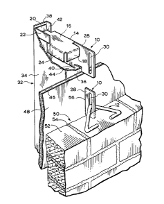
Referring fir6t to Figure6 1 to 4 of the accompanying
drawings, a brick tie has two parts 10, 12. The first part 10
is made of galvanized stainless steel sheet metal bent to the
shape shown, with a body portion 14 having a horizontal main
web-like member 16. A first flange 18 extend6 downwardly from
the front end of the web-like member 16, and a second 20
extend6 upwardly from the rear end of the web-like member 16. .
A third flange 22 extend6 upwardly from the rear part of one
side wall of the web-like member 16, and a fourth flange 24
extends downwardly from the front part of the 6ame 6ide of the
web-like member 16. .
The first part al60 has a fifth flange 26 which extends
downwardly from the web-like member 16 on the opposite 6ide
thereof to flange6 22, 24. The fifth flange 26 extend~
1326963
forwardly beyond the body portion 14 to form a projecting
portion 28. The projecting portion 28 has a vertical slot 30
near its free end.
The brick tie i8 used in a wall construction which has a
series of vertical channel-shaped members 32 (only one of which
is shown in Figure 1). Each channel-shaped member 32 has a
side wall 34, front wall 36, rear wall 38 and front and rear
side flanges 40, 42 which extend rearwardly and forwardly a
short distance from the front and rear walls 36, 38
respectively to form an opening 44 in the side of the channel-
shaped member 32 opposite the side wall 34. A drywall panel
46 extends along the front of the channel-shaped members and
may be provided with a vapour barrier sheet 48 on its front
surface. The drywall panel 46 i~ secured to the channel-
shaped members 32 in a conventional manner (not shown) which
therefore need not be described here.
The wall construction also includes a brick wall 50
comprising bricks 52 and mortar 54, the brick wall 50 being
spaced a short 2istance from the front of the drywall panel
46.
Before the brick wall 50 is constructed, a person of the
appropriate trade installs the first parts 14 of the brick ties
from inside the building being constructed. AB mentioned
earlier, the required position of each brick tie can readily be
determined by persons skilled in the art using known laser
measuring equipment. At the required brick tie position, a
vertical slot 56 is cut in drywall panel 46 and vapour barrier
48. The installer then maneouvers the body portion 14 of the
,. - .,-~ ., . . ~ , . . .. . . .
1326963
brick tie into the channel-shaped member through its side
opening 44. This can be achieved by passing body portion 14 in
an almost vertical orientation through the side opening 44. At
the same time, the projecting portion 28 of the first part 10
of the brick tie is caused to pass through slot 56.
The body portion 14 is brought to a horizontal
orientation to cause the front and rear flanges 18, 20 to wedge
against the front and rear walls 36, 38 respectively of the
channel-shaped member 32. The upward and downward side flanges
22, 24, engage the 6ide wall 34 of the channel-shaped member 32
to assist in maintaining the body portion 14 in the desired
orientation shown in Figure 1.
When the brick wall 50 is subsequently being constructed
by a bricklayer, it is a simple matter for the brick layer to
insert a second brick tle part 12, through the slot 30 in the
pro~ecting portion 28 of the first brick tie part 10 so as to
attach the second part 12 to the first part 10. The slot 30
provides a limited amount of vertical movement of the second
part 12 relative to the first part 10. The second part 12 can
thus be positioned on top of brick 52 as shown in Figure 1, so
that when mortar 54 is placed on top of the upper row of bricks
52 shown, and the next layer of bricks 52 is laid, the second
brick tie part 12 wlll be embedded in the mortar.
An alternative embodiment is shown in Figures 5 and 6,
and where applicable, the same or similar reference numerals
will be used to indicate items which are identical or similar
to those shown in Figures 1 to 4.
,, .
1326963
The first part 110 of the brick tie shown in Figures 5
and 6 has a body portion 114 with a horizontal web-like member
116, a front flange 118, an rear flange 120, an upward side
flange 122 and a downward side flange 124. The web-like member
116 has a lateral extension 126 with two longitudinally-spaced
apertures 128, 130. The second part 112 of the brick tie is a
rod-like member with a straight forwardly extending main
portion 132, and a transversely-extending front end portion
134. The rear part 136 of the second part 112 extends through
the aperture 128 in the web-like member 116 of the first part
110 from the top to the bottom thereof and through the aperture
130 in the web-like member 116 from the bottom to the top
thereof. As the rear portion 136 passes upwardly through
aperture 130 to the top of web-like member 116, it is reversely
bent to provide a short free end portion 138 lying on the top
of the web-like member 116. The second brick tie part 112 is
thereby secured to the first part 110.
During wall construction, holes 156 are made in the
drywall panel 46 from within the building at calculated
positions as described in connection with the previous
embodiment. Each brick tie is then installed by pushing the
tran6verse front portion 134 and adjacent part of the main
portion 132 of the 6econd part 112 through the hole 156, at the
same time maneouvering the first part 110 into the channel-
shaped member 32 through the side opening 44 and wedging the
first part 110 in the channel-shaped member 32, again in a
similar manner to that described in connection with the
previous embodiment.
- . . ..
1326963
The advantages of the present invention will be readily
apparent to a person 6killed in the art from the above
description of preferred embodiments. Other embodiments will
also be readily apparent, the scope of the invention being
defined in the appended claims.
' '