Note: Descriptions are shown in the official language in which they were submitted.
~ ~32703~
¦ Title of the Invention
.SIMPLIFIED CURRENCY DISPENSER
~ I
I ¦ Field of the Invention
. `
. The invention is in the field of currency dispensers
. ¦ and xelates more particularly to a currency dispenser es-
¦ pecially adapted for use at installations involving a high
volume of low dollar amount transactions.
. Bac]cground of the Invention
. I
l ~ There are known in the prior art a number of devices
,~ 10 1 ~for dispensing currency ~rom a numher o~ supplies correspond-
ing respectively -to different denominations of bills. One
~ , example of such a currency dispenser is shown and described
,. ¦ in applicant~s U.S. Patent 4,660,822, issued April 28l 1387.
Currency dispensers of the type shown
in this patent are particularly adapte~ for use in rclatively
i secure installations such as banks and the like, whcrein
~' ' I
each individual transaction involves a relatively large sum
¦ of money:~ At such an installation, moreover, the number of
transactions per unit time is not partic:ularly si~nificant.
' ¦ There are many locations at which a very large
.: ~ ¦number .of relatively low dollar amount transactions must
¦be accomplished in a short period of ti~e. Retail outlets
such as fast food stores and convenience stores are ~xamples
1f such locationsA It will readi~.y be appreciat~d tha~ the
speed and accuracy with Which transactions can be carri~d
¦ out in such locations corltributes to the overall vol-lm~. of
~r~ I business and result in profit to the proprietor. Customer
~atisfaction is enhanced by any reduction in the perio~ of
.,
'' I
1327031
time the customer must wait in line.
Recogni~ing the desirability o~ the use of an auto-
matic currency dispenser in a location such as a fast ~ood
l shop, consideration must also be given to other factors.
¦ The dispenser must be accurate and reliable. It must be
secure~ It should be simple and inexpensive for the result
achieved thereby. It should be compact to permit its use
¦ on relatively crowded countertops. It is desirable that
it have under counter capability both ~or security and space
I saving considerations. It should be compatible with coin
dispensing mechanisms. It should be relatively easy to manu-
, facture and to service.
¦ Summary of the Invention
~: I
We have invented a simplified currency dispenser
1 which is especially adapted for use where a high volume of
ll relatively low dollar amount transactions are being carric-~
I! out
! An object of our invention is to provide a
1l simplified currency dispenser which is accurate and reliable.
-~ 2Q I ~ further object of our invention is to provide
¦ a simplified currency dispenser which is simple and compact.
- j, Yet another object of our i~vention is to provide
a currency dispenser which is inexpensive.
A still further object of our invention is to pro-
2S 1I vide a simplified currency dispenser which is casy to serv~ce.
`;
,
--2--
J ~
. ~
~327~3~
2a
Specifically, the invention relates to apparatus for
dispensing a predetermined mix of bills from respective
supplies of bills of different denominations including in
combination, an upper casing section, respective first and
second means in the upper casing section for holding the
supplies of bills of different denominations, first means in
the upper casing section adapted to be driven to advance a bill
from the first supply toward a delivery location, second means
in the upper casing section adapted to be driven to advance a
bill from the second supply toward the delivery location/ a
lower casing section, first and second prime movers in the
lower casing section, means for detachably connecting the upper
and lower casing sections, and means for connecting the
respective prime movers to khe advancing means.
The features of our invention will appear from the
following description.
Bxief Descripkion of the Drawinas
In the acco~panying drawings ko which reference
rn/
~32~31
is made in the instant spacification and which are to be
read in conjunction therewith and in which likc refererlce
numerals are used to indicate like parts in the various views:
FIGU~E- 1 is a sectidnal view of our simpli~ied
currency dispenser.
FIGURE 2 is a plan view of the drive and roller
mechanis~ of our simplified currency dispenser with the ele-
ments ~hown in the same plane for purposes of clarity.
FIGURE 3 is a fragmentary sectional view of our
simplified currency dispenser.
FIGURS 4 is a side elevation with the cover removed
of our simplified currency dispenser.
FIGURE 5 is a fragmentary sectional view of one
of the dispensing units of our currency dispenser.
1 FIGURE 6 is a side elevation of an alternate embodi-
¦ment of our simplified currency dispenser, with parts rcmoved.
FIGURE 7 is a plan of the bill alevating mecl-anism
;~ I shown in FIGIIRE 6 with parts removed.
¦ FIGURE 8 is a plan view of the keyboard and display
; 20 ¦Iportion of our simplified coin dispenser.
FIGURE 9 is a block diagram illustra~ing the rela-
¦tion~hip of the central proces3ing unit of our simpliEied
¦coin dispenser to the peripheral apparatus.
1 FIGURE 10 is a schematic diagram illustrating the
25 ¦portion of the analog circultry of our dispenser incorporating
various sensing means.
FIGURE 11 ls a schematic view of another portion
of the analog circuitry of our currency dispenser illustrating
other sensors.
~ FIGURt ~3 9 a iragmentary scheratic view 11~us-
. ` I ~ ,
I '~
"-~ 1327~3~
trating a pulse encoder which may be incorporated in our
simplified currency dispenser.
FIGURE 13 is a schematic view of the motor control
circuitry of our simplified currency dispenser.
FIGURE 14 is a diagrammatic view of a portion of
the microprocessor board of our simplified currency dispenser.
FIGURE 15 is a diagrammatic view of another portion
o~ the microprocessor circuitry of our simplified currency
dispenser.
FIGURE 1~ is a dia~rammatic view of a further por-
tion of the microprocessor board of our simplified currency
dispenser.
FIGURE 17 is a diagram~atic view of a still further
orti~n of the microprocessor board of our simplified currency
dispenser.
FIGURE 18 is a diagrammatic view of a further portion
of the microprocessor board of our simplified currency
dispenser.
FIGURE 19 is a schematic view of the display control
¦circuitry of our simplified microprocessor.
FIGURES 20 through 29 make up a flow diagram of
¦the control program of our simplified currency dispense~.
~ ' i
Description of the Preferred Embodiment
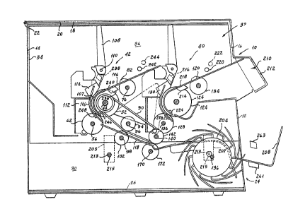
I Referring now to FIGUUES 1 to 5 of the drawings,
¦ our currency dîspenser, indicated generally by the rsference
¦ character 10, includes an outer casing ha~ln~ a front wall
12, a back wall 14, side walls 16 and a top wall 18. The
top wall lB ~ncludes a cover 20 pivotally mounted on a hinge
¦22 for movement between an open position at which the supply
¦of bills to be dispensed can be replenished, and a closed
¦position at which the interior of ~he casing is inaccessible.
¦ If desired, a lock may be incorporated in the apparatus to
-4-
I
I- I ~327~31
I
I
secure the cover in its closed position.
In order to facilitate the manufacture of our dis-
penser we assemble the apparatus in two parts; one of which
l is a lower frame section indicated generally by the reference
¦ character 24, comprising a base 26 and side walls 28 and
¦ 30 spaced inboard from the lateral edge of the base plate
l 26. An upper frame section indicated generally by the refer- -
1 1 ence character 32 of our apparatus includes a back wall 34,
¦ and spaced side walls 36 and 38 which register with the side
1 walls 27 and 28 of the lo~er section 24.
¦ Our dispenser includes a first dispensing unit
j indicated generally by the reference character 40 which may,
¦for example, be adapted to dispense a note of the lowest
¦denomination, such Eor example ~s a one dollar bill. ~ second
¦unit indicated generally by the refcrence character 42 may
¦be arranged to dispense bills of the next to lowest denoml-
.~ ¦nation of currency, such for example as five dollar bills.
;, 1 Since the units 40 and 42 are substantially id~nti-
. ¦cal, only the unit 92, for e~ample, will be described in
1detail. In connection with this description, it is to be
¦understood that for purposes of clarity, tbe locations of
. ¦the shafts in FIGURE 2 have been shown as being all in the
¦same plane and accord~ngly spaced along the length o~ the
upper frame section 32.
~: 25 l The un~t includes a feed roller shaft 44 rotatably
~ ¦supported in respective bearings 46 and 48 carried by thP
I . ¦sides 36 and 38 of the upper frame unit 32. A pair o~ uppcr
~ feed rolls 50 and 52 are supported in spaced relationship
: ~on the shaft 44 for rotation therewith. An upper idler ac-
~e1erating roller S is carr1ed by the shaft 44 botween tho I
, ................ ,._ r
1: ~3~7~
. l ,
I
two rollers 50 and 52.
We mount a lower accelerator roller shaft 56 in
bearings 58 and 60 carried by th~ walls 36 and 38 of the
¦ upper section 42. Shaft 56 supports for rotation therewith
5¦ a lower accelerating roller 62 at a location at which It
¦ cooperates. with the upper accelerating roller 54. Shaft
l 56 also carries a gear 64 which meshes with a gear 66 carried
¦ by shaft 44 for rotation therewith. A pulley 68 is adapted
to be driven in a manner to be described to rotate sha~t
101 5~.
Shaft 44 also carries a gear 70 of reduced diameter
. which i9 adapted to drive a timing belt 72 which also engages
.~ la p~lley 74 carried by a shaft 76 supported in respective
,~ ¦bushings 78 and 80 carried by the sides 36 and 38. Shaft
.; 15176 supports a -picker roller 82 which, in operation of the
¦apparatus, i~ adapted to remove the lowe~nost sheet o~ a
¦stack supported thereabove and to feed it to the rolls 52.
. Respective one-way clutch bearings 83 and 85 mount
b:, ¦pulleys 84 and 86 on shaft 44 at positions ou~board o~ the
20¦ feed rollers 52. Pulleys 84 and 86 receive respective belts
s 188 and 90. These belts 88 and 90 extend around respective
~ I pulley~ 92 and 94 rotatably supported on a fixed shaft 96
r: ¦extending between the sides 36 and 38. Another flxed shaf~
~ 1 98 extending between the sides 36 and 38 rotatably carries
t~ ~ 25¦ a pair of rollers 100 and 102 at locati~ns corresponding
~' . ¦ to the pulleys 92 and 94 so that the rollers 100 and 102
. . ¦ cooperate with the belts 88 and 90 to advance bills in a
manner to be de3aribed.
¦ ~he five~ dlspenser 92 includes a support 106 adap-
30¦ ted to receive a st ck oE sheets cr bllls to be dIspcn~od.
I ~ '
,:
.~
132~031
A sheet retainer 108 is supported on a pivot 110 carried
by a bracket 112 pivotally mounted on the frame. Bracket
112 also carries a sheet stripper assembly 114 which cooper-
l ates with the feed roller 52 to ensure that only one sheet
5¦ at a time is dispensed.
¦ We form the platform 106 with a pair of lower curved
¦ guide portions 107, one of which can be seen in FIGURE 1,
extending around shaft 44 inside of the outer peripheries
of rollers 52 and outboard of the respective rollers.
10¦ curved guide 116 cooperates with the feed rollers 52 to guide
the leading edge of a sheet to the nip between the accPlera-
lltion rollers 54 and 62. The operation of the feed rollers
: !1 52, shoes 114 and acceleration rollers 54 and 62 in advancing
I sheets, is m~re fully descr ~ d in applicant's U.S. Patent 4,474,365 issued
- 15~October 2, 1984. Sheets delivered by the acceleratin~ rollers
54 and 62 are guided into the nips between belts 88 and 90
¦ and rollers 100 and 102 by a guide 118.
The anes dispensing unit 40 supported on the upper
; frame section 32 includes a support platform 120, feed rollers
201122 and 12~, an upper idling accelerator roller 126, a lower
- ¦acceleratin~ roller 128, strippers 130 and a picker roller
134, all of which function in substantially the same manner
as do corresponding elements of the unit 42. The shaft 136
~` which supports the lower accelerating roller 128 carries
25a pu~ley 138 adapted to be driven in a manner to be d~scribed
~to drive the elements of the unit 40.
¦ Belts 88 and 90 extend around respective grooves
in an upper drive through roller 142 rotatably supported
l on a stationary shaft 140. We loosely mount the ends oE
30¦ shaft 140 in the sides 36 and 38 to permit it to be biased
~ -7-
1~27031 ~
¦to a drum posi~ion by respective springs 141 and 1430
; I The structure thus far described is assembled witt~
the upper frame section ~2 before the two frame sections
¦are secured in cooperative relatlonship. We have found that
¦this operation greatly facilitates the manufacture of the
¦ completed ~ssembly.
¦ A motor 144 having a shaft 146 supported in a side
wall 28 of the lower frame section 24 carries a pulley 148
¦which drives a belt 1500 When the ~o frame units 24 and
l 32 are assembled in cooperative relationship the belt 150
¦ is engaged with the pulley 68 so that upon energization of
, I the motor 144 the fives dispensing unit 42 is driven.
i A' second motor 152 has a shaft 154 supported in
¦ wall 28. Shaft 154 carries a pulley 156 which drives a belt
, 15 l 1S8. When the apparatus is assembled, belt 15~ is engaged
¦ with pulley 138 so that upon energization of motor 152 pulley
138 is driven to cause the ones dispensing unit ta operat~.
~ A third motor 16Q having a shaft 162 rotatably
,............... I
supported in side 28 is adapted to drive a pull~y 164 ~hich
recelves a belt 166. Belt 16S is adapted to drive a pulley
¦168 carried by a shaft 170 rotatably supported in the sides
.. I
27 and 2B of the lower ~rame section. Sha~t 170 carries
¦ a lower feed~hrough rol]er 172 which cooperate~ with roller
142 to advanca shaets to the stacker mechanism to be de-
¦ scribed.
Shaft 162 carries a second pulley 174 which drives
a belt 17~ extendlng around an idler pulley 178 rotatably
¦supp~rted on a stub sha~t 180 carried by side 28. ~ second
! smaller diame~er pulley lB2 on shaft 1~0 dr~ves a belt 184
¦ which extends around a second ldler pulley lA6 ro~a~ably
,~ I supported on a stub shaft 188 carried by the sides 28. A
~, .
.~
1327031
I
¦second pull~y 190 on shaft 188 drives a belt 192 which extends
¦around a pulley 194 carried by the stacker shaft 196 rotatably
¦supported in bearings 198 and 200 in the sides 27 and 28
of tha lower frame unit. Shaft 196 carries for rotation
5¦therewith a pair of spaced stacker wheels 202 and 204. Refer-
¦ring to FIGURE 5, a slotted guide 206 receives the sheets
delivered by the rollers 142 and 172 to be ac~ed upon by
¦ the stacker wheels 202 and 204, and thus delivered to the
output tray 208 of the apparat~s.
10l The apparatus includes a push button and display
¦llnit indicated generally by the reference character 210 lo-
cated behind a window 212 formed in an extension of the front
part o~ the top 20.
I When the various components save for the belts
151 150 and 158 have been assembled in the upper and lower halves
`, i32 and 29 in thc manner described hereinabove, the upper
Isection 32 is placed on the lower section so that pairs oE
¦lugs 205,207 and 209,211 secured to the respective sides
¦36 and 38 at spaced locations along the lower sdges thereof
20l overlie sides 28 and 30. Bolts ~13 and nuts 215 hold the
¦sections assembled. It will readily be appreciated that
this construction not only facilitates the manufacture o~
lour dispensar but also enables servicing and repair to be
¦expeditiously acaomplished merely by separating the sections.
25l When the upper and lower sections are assembled
¦in the manner descrlbed the roller 14~, which is carried
¦by the biased shaft 140, moves into engagement with roller
¦ 172 to provide a drivin~ engagement therebetween. Under
¦ this condition the action of the clutch bearings 83 and 85
30come into play. If motor 160 is energized so that shaEt
¦ 170 is drlven Dt i D norma1 sp~ed, Cl~ltCh bo~r1ngs 83 and
..
~ ¦ 1 3 2 7 0 3 1
85 are overrun. If, however, motor 160 is not energi~ed
while bills are being delivered from unit 42, the bearings
engage so that roller 142 dri~es roller 172 and the stacker
mechanism. In this way bills are prevented from piling up.
We provide our dispenser with a plurality Oe scnsor
pairs for affording indications of various conditions of
the apparatus. A first sensor pair including a light source
214 and a phototransistor 216 may be employed to sense the
presence of a supply of ones on tha tray or platform 120.
Light received by phototransisto~r 216 directly fro~ the source
214 produces a ~ignal indicating absence of any ones on the
support 120.
¦ A light source 220 and a phototransistor 222 respon-
¦sive to light from the source 220 provide a signal indicatin~
l that the supply of ones on the support has dropped to below
a predetermined level. One of the elements 220 and 222 i5
¦placed at one side of the stack and the other at the other
¦side of the atack so as to operate on light received directly
¦ from the source.
l A source 224 of light arranged at one side of the
l path followed by a one dollar note being delivered by the
¦ roller 124 causes a photodiode 226 to produce an output signal
which indicates not only that a bill has been fed, but which
also provides a measure of the amount of light transmitted
l by tha bill so as to afford an indi~ation of a ~ouble feed
i~ a manner known to the art.
A sensor unit made up Oe a light source 228 spaced
from a light sensor 230 is so arranged that the teeth 234
¦ of an encoder wheel 232 carried by shaft 136 pas~ through
¦ the space between ~he two ele~ents 228 and ~30 of the s¢nsor.
In this way we generate a number of pulse~ which is propor-
-10- 1
.1 '
: I '~'
`'
` .
` ~
132~031
¦tional to the length o~ a bill or note being fed by the ones
unit .
¦ A light source 236 cooperates with a 3ensor, such
las a phototransistor 238, by directing rad.iation through
5la window 240 in the platform 106, so that radiation received
¦by element 238 indicates the abs0nce of a stack of bills
on platform 106.
: Another sensor set including a li.ght source 242
and a detector, such as a phototransistor 244, operates on
10¦direct illumination to afford an indication that the stack
of fives on the support 106 has fallen to below a predeter-
¦mined level.
i
; A source 246 and a infrared diode element 248,
such as a photodiode, mounted respectively on the curved
15portion 107 of the platform 106 and on the curved guide 116,
, ~fford an indication of the amount of radiation passing
through the bill, thus to enable us to generate not only
~ la count signal but alsD a signal indicating a double feed.
: ~ !i Referring to FIGURES 2 and 1~, a sensor pair includ-
20ing a light source 228 and a phototransistor 230 cooperate
with an encoder wheel 232 on ~he shaft carrying roller 128
. so t~at the teeth 234 of tbe wheel generate a train of pulses
¦affording a measure of the length of a ~note being dispensed
by the ones unit. A second sensor pair including a light
25~ source 250 and a light sensitive element, such as a photo-
transistor 252, cooperate wlth an encoder ~heel 251 on shaft
¦ 56 so that the teeth 253 of ~he wheel 251 passing throu~h
¦ the 3pace between the elements 250 and 252, causes the genera-
~i ~ tion of a train oE pulses affording a measure of the len~th
. 301 of a note being dispensed by tha fives unit.
¦ Roeorring n ~ to ~GuRe 5, ~u provido our dispenser
..
'`'
. 132~Q31
¦with mean~ for generating a Uverifyu signal indicating the
¦fact that a note being fed by a dispenser 40 or 42 has, in
¦fact, reached the stacker wheel 204. We mount a suitable
¦light source 254 on a bracket 256 carried by the upper er~me
¦member. Light from the source 254 extends across the p~th
of movement of a one traYelling from the unit 40 toward the
stacker wheels. This light, after having ~raversed the one's
path, crosses the pa~h of ~ five being delivered by the
rollars 142 and 112 to the stacker. A sensing device 262
l supported by guide 118 on the other side of the Eive's path
rsceives the light. O~ing to the fact that this arrangement
is common to both the one's path and the five's path and
¦ that both ~he one's deli~ery and five's deliverY units 40
and 42 do not operate at the sa~e time, we are able to achieve
l the verification signal by the use of only a single pair
1f elements.
¦ Finally, we provide the output tray 208 with a
¦pair of sensing elements comprising a light source 261 and
~a light sensitive element 263 such as a photodiode eor detect-
ing the presence of one or more bills in the outpU$ tray.
As will be exp3ained more fully hereinbelow, we employ this
¦signal to inhibit further operation of the machine under
¦certain conditions until the bills ~ave been removed from
¦the output tray.
In som~ installations it may be neces5ary or desir-
able to pos~tion the di~penser unit below the surface counter
and yet provide for delivery of the bill~ at or ad~acent
to the co~ntertop.
I Referring now to FIGS. 6 and 7, we h~ve s~lown an ,
l alternate embodiment of our simplified curr~ncy dispenser i
ln ~bich we ~ecure tDp delivery unlt indicated gener~lly
:~ ,
.
1327931
by the reference character 276 to the front of the assembled
top and bottom sections 32 and 34 of the machine. This may
¦ be accomplished by any suitable ~e~n~ known to the art.
I As will be apparent from the description hereinbelow, this
¦1 top delivery unit 276 replaces the lower stacker wheels 204
1 and 206 and the lower delivery tray 208, as well as thc dis-
¦ play panel 210 of thc form of our simplified currency dispcn-
ser shown in FIGS. 1 to 5.
¦ The unit 276 includes a pair of side panels 278
l and 280 which rotatably support a shaft 282 by means of besr-
ings 284 and 286. Shaft 282 carries for rotation there~ith
a pair of spaced stacker whe0ls 288 and 290 ~or delivering
;i
~` I bill~ to a tray 291 located near the top of the apparatus.
I Shaft 232 also carries a pul]ey 292 connected by a belt or
;¦ 0-ring 294 to the drive pulley 190 carried by shaft 188.
It will readily be appreciated that some slight rearrangement
of the axes of rotation of th~ pulleys shown in FIG. 4 may
, be necessary to prevent interference between the belt 294
and other elements.
, When employing the top delivery unit 276, we provide
a guid~ or guides 296 forming an extension of th~ guides
1,
118 dir~cted generally upwardly towards the stacker wheels
~, 288 and 290 and guides 297 extnnding around th~ axis of shaft
282. ~ pair of belts 298 and 300 extending around rollors
l, 172 are guided around respective relatively larger diamcter
¦ pulleys 302 and 304 rotatably supported on shaf~ 282 at posi-
tions spased inboard of the stacker wheels 2~8 and 290.
il¦ It is to be understood that the drive system asqoci-
i ¦ ated with the top delivery unit 276 is subf,tantially the
1 same a3 that of the form of our invention shown in FIGS.
_13_
',:
. ~
~ '
132~Q3~ :
¦1 to.S in that the belts 298 and 300 are driven ,at a greater
¦speed than are the stacker wheels 288 and 290 so that bills
¦are positively forced into the spaces between adjacent fingers
¦of the stacker wheels.
; 5 j We provide respective first hold-down roller3 306
and 307, for the belts 298 and 300. Resp~ctive pairs of
¦ idler rollers 308 and 310 and 312 and 314 associated with
the respective belts 298 and 300 prevent bills from flying
away from those pDrtions of the belts extending from the
¦location at which ones are fed upwardly toward the stacker
¦wheels 288 and 290.
From the structure just described, it will readily
be apparent that in operation of the form of our currency
l¦dispenser shown in FIGUReS 6 and 7, bills delivered by the
1 15 .¦fives unit 42 are received by the upper surfaces of the belts
¦298 and 300, as viewed in FIGURES 6 and 7, pass under rollers
,l306 and 307 and are carried upwardly under the pairs oE idler
¦rollers 308 and 310 and 312 and 314 and are fed into ~he
pockets Eormed by adjacent fingers of th~ stacker wheels
. 20 ~i288 and 290. Rills fed by the nnes unit 40 are received
by belts 298 and 300 at ~he location between roller 306 and
. ¦ roller 308, as viewed in FIGUR~ 6. Further, as is pointed
.: I out hereinabove, the belts 298 and 300, are driven at a some-
~lwhat faster ~peed than th~ surface speed of the stacker wheels
2S l 288 and 290 so that bills are pogitively forced into the
I spaces between adjacent fingers of the stacker wheals 28~
, and 290. As the stacker wh~el~ continue to rotate, thcy
I lay ~uccessive bills do~n on a tray 316 from which they c~n
::~
. be retrieved by the operator oE the d~spenser, It is to
: 30 be undarstood that when the form of our currency dispenser
¦illustrated ln FIGURES 6 and 7 is lnstalled below the counter
_
. .
`~ 1 13271~3~ ~:
¦at the establishment at which it is located, bills on the
tray 316 are accessible at a location just below the top
o~ the counter.
Referring now to FIG. 8, the built-in keypad ~nd ;
display panel 210 includes a plurality of numerical push-
buttons 264 which may be actuated to enter information as
desired. A START-CLEAR button 26~ is actuated to set the
unit in the count mode ~hil~ COUNT, BATCH and ~ESET buttons
268, 270 and 272 are actuated to control the operation in
the count mode. A display 274 gives a visual indication
o~ output information. ~ -
Operation of our apparatus in the dispense mode
is controlled by a remote or point-of-sale keypad and display
lunit, indicated generally by the reference character 372.
15 1l Unit 372 includes a keypad having numerical input keys 373,
as well as NET SALE, AMOUNT TENDE~ED and ~ISPENSE keys 374,
il37s and 376. ~ display 378 affords a visual indication of
,joutput information in the dispense mode.
Referring now to FIG. 9, we have shown the relation-
!Iship bet~Jeen the central processing unit indicated generallyby the reference charaater 488 o~ our apparatus, to be de-
scribed more fully herelnbelow, and various sources of input
information such as the keyboard, the empty supply signal
I ¦ generators, the low supply signal nerators, the count and
!¦doubles signal generators, the encoders, the verify sensor
~ ¦iand the output tray sensor. The central processing unit
I ¦uses this information in a manner to be described more Eully
¦hereinbelow to actuate the display, the motor drives and
¦ ~ coln dlspuns~r, I one is so p~ovided.
I ~ 31 ~
Referring now to FIGURES 10 to 13, in the analog
portion of the control system of our dispenser, a voltage
divider made up of resistors 380 and 382 provides a reference
potential which is applied to the inverting terminals o~
5¦ operational amplifiers 384, 386, 388, 390, 392 and 394, asso-
ciated with the phototransistors 216, 238t 222, 244, 263,
and 262. When, for e~ample, light from the diode 214 impinges
¦ on the base of transis~or 216, ~he transistor conducts to
I apply a signal to the non-inverting input of a~plifier 384
101l to indicate that there are no documents in the oncs supply
tray. Conversely, when a supply of documents is prcsent
!i the nature of the signal on line 396 indicates this fact.
, Respective outp~t lines 398, 400, 402, 404 and 406 associated
.I with the respective amplifiers 386, 388, 390, 392 and 394
15I indicate the presence or absence of $5 notes in the $5 input
¦ tray, the ~act that the stack of ones has or has not ~eached
j a predetermined low point, the fact that the stack of Eives
j has or has not reached the predetermined low point, the pre-
sence or absence o~ notes in the stacker tray and a signal
20¦ indicating that no~es dispensed have, in fact, been fed to
. j the staclcer.
As has been poin~ed out hereinabove, we provide
.~ ¦ a pair of sensors including LEDs 224A and 224B and photodiodcs
¦ 226~ and 226~ for pro~ucing signals from which a count of
~ 25l the numbar of ones dispen~ed may be obtained and ~rom ~hich
.~ I there i~ indicated the presence of overlapping bills. Respec-
: I tlve feedback networks includlng transistors 408 and 410
¦ operate to maintain the output level of light from the L~Ds
. I 224A ~nd 224B, substantially constant in a manner known to
: 30¦ the art. A ref~rence potential i5 applied to the inverting
I
.
13Z7~31
input of a COUNT operational amplifier by means of a voltage
divider mad0 up of reslstors 416 and 418. When the light
I from LED 224A i5 interrupted, the signal is applied to an
j input resistor 420 at the non-lnverting input of amplifier
~ 412 to produce a COUNT ~1 signal on an output line 422.
In a similar manner, an operational amplifier 414 associated
with diode 226B provides a COUNT Bl on line 424. Another
operatlonal amplifier 426 responsive to the condition oE
il diode 226A provides an input to operational amplifier 43n
~I to generate a DOCSIG Al on line 434. Similarly, an op~ra-
¦ tional amplifier 428 responsive to the condition of diode
1 226B provid0s a signal for an amplifier 432 to generate a
., . .
DOCSIG B1 on line 436.
Tha pair of sensors including LEDs 246A and ~ and
diod0s 248A and 248B associated with the $5 note dispensing
j system are employed to generate signals similar ~o those
described hereinabove in connection with the dispensing o~
i1
j one dollar notes. Resp~ctive feedback circuits includlng
transistors 438 and 440 maintain the output light levels
, "
ll of LEDs 246A and 246B substantially constant. Respec~iVe
operational a~plifiars fl42 and 444 associated with diodes
- 1~ 248A and 248B provide COUNT A5 and COUNT B5 outputs on lines
; ¦ 446 and 448. Operation~l amplifiers 450 and ~52 are respon-
5iV~ to the conditions of diodes 248A and 24B~, actuate ampli-
~ ~iers 454 and 456 to provide DOCSIG A5 and ~OC81G B5 signals
on lin~s 458 and 460.
As shown in FIGURE 12, LSD 22B is so arranged with
I referenc~ to wheel 232 and ta0th 234 as intermittently to
cause light to imping0 upon the basa of ~rans~stor 230 to
~0 ¦ ganerate an ENCODE signal ~or on0s. A ~imilar circuit respon-
sive to the outp~t of transistor 252 provides an ~NCODE si~nal
-17-
: ~ .
.:
,.
:` . .
132~Q31
for fives.
FIGURE 13 illustrates one form of control circuit
which may be used to control the l's and 5's dispe~sing motors
152 and 144 and the stacker motor 160 by connecting them
to a suitable source of DC potential having a terminal 462.
A STACKER signal on line 464 renders a transistor 466 conduc-
tive to apply the potential at terminal 462 ~o the motor
160.
A FSED 1 signal on line 468 causes a transistor
470 to apply th2 potential of terminal 462 to the motor 152.
A BRAXE 1 signal on the line 472 randers a transistor 474
conductive to connect a shunt resistor 476 across the motor
152 to brake tha motor after the feed signal disappears.
A FEED 5 signal on a line 478 causes a transistor
l 4~0 to apply the potential at terminal 462 to the motor 144.
I After the feed signal disappears, a BRAKE 5 signal on a line
~ 4~2 renders the transistor 484 conductive to connect a shllnt
j¦ resistor 486 across motor 144 to brake the same.
¦¦ Re~erring now to FIGURES 14 to 18, the ee~tral
¦I processing unit 488 1ncludss a mlcroprocessor 490 such as
i a Z-80 manufactured by Zilog, Inc. of Campbell, California,
I' having a non-maskable interrupt terminal 492 ~hich receives
j a signal in the event of a power failure, as is known in
1 the art. The microprocessor 490 receives reset pulses at
¦ a reaat terminal 494 and clock pulses Erom a suitable pulse
I ~ genarator ~not shown~ at a terminal 496.
I l ~s will he described more fully hereinbelow, in
¦ re~ponse to tha systam clock/pulsa~, the microprocessor eeeds
address informa~ion to a pair of bidirectional buffer circuits
~ 498 and 500 such, fo~ example, as 7411C244 which translate
¦ the inEormatio~ to n ~ddr~ss bus 502.
1~1; A~ I ~ 3 ~
; 1j Bus 502 feeds the address information into a PROM,
such as a TMSC 27256, a counter timer circuit 506, a RAM
circuit 508 such as a CDN 6264, a pair of parallel input/out-
put circuits 510 and 512, a serial input/output circuit 514,
a third parallel input/output circuit 516 and a second counter
timer circuit 518. At the appropriate times, the circuits
¦ 506, 508, 510, 512, 514, 516 and 518 feed output data to
111 a data bus 520 leading back to the microprocessor 490.
i I Respecti~e decoders 522 and 524 which may be 74~C138
I,
'~ 10 i' circuits respond to information on the address bus selectively
to enable various of the circuit chips.
,
, Outputs I01 and I04 to I07 respectively enable
I chips 510, 518, 512, 516 and 514. I02 provides one input
,~ I to a 2-input circuit OR 526 coupled to the enable termina~
!~' 15 ! of a buffer/driver/receiver 52~, which may be a 74~1C244,
the function of which will be described more fully herein-
;; ¦ below. I03 provides an input to the CS terminal oP an analog
¦ to digital converter 540. ;
¦ The signal on output line 530 of decoder 524 enables
', chip 506. ~ines 532 and 534 carry signals which clock respcc-
j tive octal flip-flops 536 and 538 which may be 7411C374 chips
to couple data from the bus 502 to the display in a manner
j to be describ~d.
` il A line 542 provides a cloc~ pulse input to a
~; 25 il buPfer/driver/rece~ver circuit such as a 74HC244 to couple
the input~outp~t request IO~Q, the memory request M~EQ, memory
¦ read RD, memory write WR and M1 gystem control output term~-
I ¦ nals oE the microprocessor 490 to respective output lines
¦ 546 and 548, 550, 552, 554 and 556 and the halt ~tate IIAI.T
~ output terminal of the microprocessor to a line 560.
¦ ~lnes 550 nd 556 provldr inputs ior an AND =ircui~
` ' i
, ~.
-~ l ~
! 13~7~3
568, coupled to the enable terminal of a transceiver 566,
¦ such as a 7411C245. Lines 546 and 556 provide inputs for
~ an OR circuit 562, the output of which is applied to an AND
¦ circuit 564, together with the signal on line 552 to supply
S ¦ an input to the directional input terminal of the transceiver
' 566. The memory request signal on line 550 provides one
input for an OR circuit, the other input of which comes from
~ address bus 502 to provide a signal input for the chip
enable terminal of PROM 504. The memory read signal On line
' 552 is applied to the output enable terminal of l~emory 504.
¦ The CTC506 which is enabled by line 530 also ~e-
ceives inputs from the M1 input/output request ~nd read lines
556, 546 and 552.
Il Referring now to FIGURE 16, the Ml, IOREQ, RD and
,I SYS CL~ lines 558, 548, 552 and 496 lines provide inputs
to the parallel inputloutput circuits 510 and 512. Circuit
512 receives condition input signals from lines 396, 398,
I 400, 402, 404, 422, 424, 446 and 448. The circuit 510 receivos
!
inputs Erom keyboard switches 572a to 5721. Svitches 572a
¦¦ to 572f correspond to amo~1nts while 5729 to l respectively
correspond to COUNT, REMIT, DOU8LE, CONTINUE, STOP and
¦ START/CLEAR.
~ 1 The MR~Q signal on line 550 pro~ides one input
¦ j1 for an OR circuit 574 which receives its other inp~t from
1l the address bus 502 through an invert~r 576 to provide a
¦¦ CSl input for RAMS08. T11e RD signal on line 552 provis1es
~1 tho output enable signal for chip 50B.
Referring now to FIGURE 16, the Ml, IOREQ and RD
l signals on lines 558, 54B and 552 pro~ide inp~ts eor circuits
¦ 514, 516 and 518. Conductors 576 and 578 leading from chip
506 provide inputs for SIO 514. Ch1p 518 receive~ respective
; -20-
~327031
¦ inputs from the ~ives encoder wheel and ones encoder wheel
1 on lines 530 and 582.
¦ Chip 516 provldes the motor control signa~s de-
¦ scribed hereinabove on conductors 464, 463, 472, 474, and
¦ 482. An output 584 of chip 516 controls a suitable acoustical
device 586 to indicate that the supply of currency being
dispensed is exhausted. Other outputs of chip 516 indicate
a power on condit~ion at a terminal 588, a ones low condition
l at a terminal 590 and a fives low condition at a terminal
l 592. These terminals may be connected to suitable indicators.
!1 In addition, the chip 516 puts out DOC ~5 ~nd DOC
A1 signals on lin2s 594 and 596, as well as DOC BS and DOC
Bl signals on lines 598 and 600.
Referring to FIGURE 17, we apply the signals on
1 conductors 434, 436, 458 and 456 to respective microprocessor ''
1 operated switches 602, 604, 606 and 608. Respec'tive invcrters
¦ apply the signals on lines 596, 600, 594 and 598 to thc
switches 602, 604, 606, and 608 to couple the signals on
; I line 434, 436, 458 and 456 to the analog's digital converter
l 540. In addltion to the IO3 signal from chip 522 t the ¢on-
verter S40 receives write and read signals on linss 552 and
554.
¦ Turning now to FIGURE 18, switches 610a to 610h
¦ provide inputs for chip 528 to set up ~he particular software
';~ 25 l which 19 to be used. More specifically, tha switches are
ao operated as to tell the microprocessor, ~or exampl~, whe-
¦ ther it i~ hooked up to a point of s~le terminal or to the
remote key p~d.
first octal flip-flop ~12 which i3 clocked by
¦ the signal on line S34 faeds signals DBL, B100, BS0, B25,
¦ B20, B10 and ~5 ~o re~pective LEDs 614a ~o 614g.
; 1 A ~econd octal flip-flop 616 which is clocked by¦
~ -21-
~ ''
.~
1327031
¦¦ the signal on line 532 provides respective output signals
¦ DIG4, DIG3, DIG2, DIGl, BCD~, BCD4, BCD2 and 8CD1 leadin~
l to the display board illustrated in FIGURE 19.
¦1 ~eferring now to FIGURE 19, we apply inpl~ts as
¦ indicated to circuit components 618 and 620 to provide four
¦ groups of outputs indicated as al to gl, a2 to g2, a3 to
¦ 93 and a4 to g4, to illuminate LEDs making up a four di~it
numbsr.
Referring now to FIGURES 20 through 29, we have
1 shown the flow chart of the program which controls our appara-
I tus. Beginning at START in FIGURE 20, the R~M 508 is first
tested. If this test is unsllcccssful, as indicated by SYSERR,
¦ proceed to FIGURE 24 display UHelp~ and halt the proyram.
l1 If the test is successful, the input/output circuits, the
ll RAM and the I~TERRUPTS are initiali~ed. Next, the display
'¦ is actuated to show an indicating designation, such for ex-
¦ ample as "8902~ which may be ths model number of the appara-
, tus. In addition, the pending ~NTERRUPTS are clea~ed and
I ths timer circuits are set.
~0 l; When the above has been accomplished, the program
1 is at ~EGIN~. This flrst detenmination to be made is whether
or not the apparatus is in the COUNT mode. As has been
polnted out he~Qinabove, the system normally is in the dis-
I pen3e ~ode. It is placed in the count mode by actuating
, the STARTJCLEAR button 266. If the anwser is yes, procced
; li to FIGURE 26 and contin~e in a manner to be de3cribed herein-
below. Assuming that t~e sygtem is not in the COUNT mode,
proceed to aDISPENSE~ in FIGURE 21. The ~IP ~witches 610a
, to 610h are read and the interface selected. When ~hDt has
l bean done a doterm~natiDn is made if the supply of ones or
¦ of fiYes is low. I~ so, ~LOa is displayed one seoond erom;
-22-
~ I
1327~31
¦ the last display and the system returns to UBEGINU in FIGURE
Il 20.
¦l If ncither the supply of ones nor the supply of
fives is low, a check is again made to seo if the switch
is set to the COUNT modo. If so, as beforet the systcm pro-
ceods to tho "COUNT MODE" of FIGURE 26. If tho switch is
not set to the COUNT mode, a chsck is mado to det~rmine who-
i! thor or not the data from the keyboard or other source has
j~ been rea~ in. If not, the system returns to the on~s or
¦, fives pocket low decision. ~f the data has boen road in,
proceed to ~CALCULATE" in FIGUR~ 22. At this point, tlle
amount to bo dispensed is displayod and a calculation is
made of the-numbor of ones and tho number of fives roquirod
I¦ to make up that amount. For example, if $18.00 is to be dis-
l¦ pensed, a calculation is mado that three onos and threo fivos
aro to be dispensed for a total of documents or bills of
- 'I six.
Next, a check is made to determine if the system
` has called for moro than twonty documents to be dispensed.
, If so, the systom 90e5 tD "ERRORS~ in FICURE 25, displays
Helpu and halts the program.
If tho systom indicatos that not more than twenty
documents have b~on called for, a decision is mado as to
1 whether or not any ~ives are to be dispensed~ If so, a check
! i5 mado to dotermine whothor or not thore are any f ives in
ii th~ supply tray. If so, a five dollar note is dispensod
¦ and the syste~ proceeds to determine whether or not any errors
have occurred. I~ so, the system agaln proceeds to FIGURE
1 25 to display ~Holp~ and halt the program~ If no errors
havo occusred, the system roturns ~o tho detormination o~
whether or not there are any fives to dispense. If moro
-23-
~ 4
1327~31 ~'
Il fives are to be dispensed, a check again is made if there
are any fives in the pocket. If so, another five i9 dispensed
and the system proceeds.
When no more fives have been called for, the system
proceeds to the "DISPENSE l's" terminal of FIGURE 23. It
is to be noted that if the system calls for a five to be
dispensed and no fives remain in the supply, the amount oE
leftover fives is added to the number of ones required to
I be dispensed before the system proceeds to the "DISPENSE
1 l's" terminal of FIGURE 23.
Prior to dispensing the number ot ones called for,
a check is made to determine ~hether or not more than twenty
,j documents are required. If so, the system returns to FIGURE
2~, dlsplays "HelpU and halts the program. If no more than
'1 twenty documents have been called for, a check is made to
see whether or not there are any ones to be dispensed. If
~¦ so, the system proceeds to determine whether or not there
,¦ are avilable any ones in the supply. If not, the dispensing
! operation called for obviously cannot be ful~illed and the
,I system goes back to FIGUR~ 4, displays "~lelp" and halts the
program. If there are QneS available to be dispensed, a
one is d~spensed and a check is made to see if any errors
¦¦ have occurred. If an error has occurred, the program proceedq
to FIGU~E 24 to cause R~lelp~ to be displayed and to halt
1¦ the program. If no a~ror has occurred, the program returns
¦ to the decision of whether or not any ones are to be dis-
¦ pensed. If so, it proceeds as befor~. If not, the dispQnsing
¦ operation ostens~bly is complete gnd the program proceeds
¦ to the ~DISPENS8 CHECK~ terminal of FIGURE 25.
! Yrom the ~DISPENSE C~IECK" ~erminal, a dccisiQnis made as to whethar or not any errors have occurred. If,
~24-
I '.
13'~031
no errors have occurred, the system returns to ~BEGIN" in
FIGURE 20. If an error has occurred, the offending error
or errors are displayed. Examples of errors which might
be detected are "half note" where a piece of a bill which
5¦ has ~een torn into tvo pieces is detected and "chain note"
indicating that overlapping bills have passed thraugh. These
~rrors are displayed on the display 37B as "E1" and "E2N
or the like. At the same time a loud, pulslng and audible
I beep is generated. The system then checks to determine whe-
10l ther or not the output tray is empty. If not, the loud,
, pulsing and audible beep continues to be generated to alert
i .
the operator to empty the output tray before the system will
proceed. If the output tray is empty, a determination is
'; made of whether or not the error is unrecoverable. Ie it
15¦ is an unrecovarable error, the program returns to "BEGIN"
in FIGURE 20. If the error is recoverable, it retu m s to
the ~CALCULATE" te~minal in ~IGURE 21.
Assuming that the system had been set in the COUNT
mode as indicated by the de~ision box in PIGURE 20 so that
20the program proceeded to the "COUNT" mode ~erminal o~ FIGVRE
26, first the coun~ is clseared and the doubl~s detection
is set on. A determination is then made of whether or not
the START key has been pressed. If so, ~he program proc~eds
Il to the ~C-START" terminal of FIGURE 28. At this po~nt the
Ij system first clears the count and resets the batch count.
' Next, errors ara cleared. ~ determination then is made o~
I whether the count is higher than the batch. If ss~, the count
and batch count are reset, a document is moved from the input
l tray to the output tray, and the display and batch count
30 ¦¦ are bumped. If a detenmination had been mad~ that the count
;¦ was not higher than the batch count, the program proceeds
-25-
1327031
~¦ directly to dispense a document and bump the display and
~¦ batch counts. AEter a document has been dispensed and the
display and batch counts bumped, the system proceeds to the
l! "C-CHECK" ter~inal of FIGURE 29.
1' A check of the doubles detector is made to seo
whether or not an error has occurred. If not, the system
proceeds directly to determine whether or not any other errors
, have occurred. If a doubles error is indicated, a check
,~ is made to see whether or not the doubles detection system
is active. If not, the system proceeds to determine whethe~
!~ or not any other errors exist. If the doubles detection
system i5 active and a double errors has been indicated,
the program proceeds to display the error and stop the
counter. I~ there is no dol~bles error or the double detection
system is not active and another error i5 not detected, the
program proceeds to the "C-NEXT" terminal in FIGURE 28 to
continue the count.
`If an error has been detectcd and the counter has
bean stopped, a check is then made to see if the output tray
1 20 ~ is empty. If it is, the program returns to the "C-~EGIN"
tsrminal of FIGURE 26. If an error has been,detected and
the output tray is not empty, a check is made to see whether
or not the CONTINUE or STAR~ key is pressed. If no~, the
pro3ram returns to the determination of whether or not the
25 1 output tray i9 ~mpty. If an error has been detected and
the output tray i~ not empty and one of the CONTINUE or START
~ keys ha~ been press~d, th~ system sounds a short beep to
;' remind the operator to empty the output tray and the prograln
11 returns to the determination of whether or not the tray is
30 1, empty. If the tray is empt~, the program returns to the
i ~C-BEGINR termlnal of FIGURE 26.
-26-
132~
l If, following a determination that a system is
¦ in the COUNT mode, a determination also is made that the
¦ STARI' key has not been pressed, the system makes a decision
~ as to whether or not the continue key has been pressed.
~ If so, the program goes to the ~C-CON~ terminal of FIGURE
28 leading to the clear error~ operation and the program
proceeds as before. If the CONTINUE key has not been pressed,
a check is made to soe whether the input tray has just now
I been filled. If 50, the system checks to determine whether
! or not the stacker tray is full. I~ not, the program proceeds
i to the ''C-STARTU terminal Oe FIGURE 28. If the stacker tray
is full the program proceeds to the "C-CONT~ terminal of
FIGURE 28.
, If, following a determination that neither the
¦ START key nor the CONTINUE key has been pressed and the input
¦ tray has not just now been filled, the program goes to the
"C-KEYSU ter~inal oP FIGURE 27. A determination is then
made of whether or not a batch key has been pressed. If
so, the proper LED and appropriate batch counts are set and
¦ the prog~am goes to the ~C-BEGIN~ terminal of FIGURE 26.
¦ If no ~atch key has been pressed, a check is made
;; ¦ to see if ths COUNT key has been pressed. If so~ the batch
¦ coun~ and batch ItED are eleared and the system goes to the
¦ "C-BEGINU block o~ FIGURE 26.
If neither th~ batch key nor the count key has
I been pressed, a check 1s made to see 1f the double key has
! ben pressed. If so, the ~oubles detection status and LE~
; are tog~led and the program goes bac~ to the UC-BEGINu block
of FIGUR~ 26~ If none of the batch keys or the count key
¦ or tha double key is pre~sed, a check is made ta see whether
¦ or not the =top ke ~s preas~d. I~, ~nder these condlt~onc,
. . I'~
t
i:
1327031 ~
the stop key has not been pressed, the system checks to see
if the reset key has been pressed. If so, the program returns
to the START terminal of FIGURE 20. If the stop key has
been pressed, a short beep is sounded and the program ~eturns
S to the "C-8EGIN" bloc~ of FIGURE 26. If neither the stop
key nor the reset key has been pressed, ths program returns
¦' to ths C-BEGIW block of FIGURE 26. If the stop key is n~t
Il pressed but the reset key has been pressed, the progr~m re-
1l turns to the STA~T block of FIGURE 20.
~ The operation of our simplified currency dispenser
will be apparent from the description given hereinabove.
In the normal operation of the device in the dispensc mode,
wherein change is to be given to a customer in response to
l payment for merchandise, the operator first punches in the
¦ cost of the purchase on keys 373. The aggregate is displayed.
¦ Next, the amount tandered by the customer is entered and
displayed and the display then shows tho amount to be given
in change. Tha amount in bills is determined in terms of
Il the number of flve dollar bills and the number of one dollar
1I bills reguired to make the change. Where there are not enough
¦I five dollar billa to make up the required number, a number
I Ij of ones equal t~ the same amount is added to the number of
, ones to be dlspen3ed. Tha unit then operates first dispensing
! ~i~e dollar bills ~rom unit 42 and then dispensing one dollar
l bills from unit 40 until the required amount of bills in
change has been deliYered to the output tray 208.
To cause the unit to operate in t~ count mode,
the START CLEAR button 266 is pressed to set it in th~ count
l mode. The bills to be counted then are placed on the tray
¦ 120 and the unlt begins to count. It may be operated in
¦ th~ batch CouDt mod .
!
`. i ~ ~327
., I
I
l In the course of dispensing or counting operations,
¦ errors are detected and displayed on the operative display
as coded signals.
It will be sesn that we havs accomplished the
I objects of our invention. ~Je have provided a simplified
~ currency dispenssr which is especially adapted ~or use at
¦ a location at which a high volume oE relatively low dollar
amount transactions are being carried out. Our simplified
currency dispenser is accurate and reliable. It is simple,
1l co~pact and inexpensive. It is relatively easy to construct
, and to service.
I¦ It ~ill be understood that certain features and
¦I subcombinations are o~ utility and may be employed without
,I refersnce to other features and subcombinations. This is
15 1l contemplated by and is within the scope of our claims. It
,1 is fu~ther obvious that various changes may be made in d~tails
' within ths scope o~ our claims wi~hout departing from the
! spirit of our invention. It ~5, therefore, to be understood
that ou~ invention is not to be limited to the spscific de-
- 20 ~I tails shown and described.
¦I Having thus described our invention, what we claim
~s~
., 1
.
....,..1