Note: Descriptions are shown in the official language in which they were submitted.
13271~7
TPC 076 P2 -1-
PIVOT JOINT
Thi~ invention relates to a pivot ~oint which is
particularaly but not exclusively useful in the
manufacture of windscreen wipers.
In the manufactue of windscren wipers, a number
of pivot joints are used, particularly between the arm and
blade and between the various yokes and/or levers of the
blade itself.
Problems exist in the manufacture of windscreen
wipers due to the necessity, very often, of pivoting metal
parts togeher. These tend to be noisey and have a
tendency to suffer from wear and corrosion. Various
proposals have been made for overcoming these problems,
for example, by the provision of plastics members between
the metal of the joints, but these have not proved ~ -
entirely satisfactory from a manufacturing standpoint
although they have worked satisfactorily in practice. -
In particular, problems have been caused by the
necessity, during manufacture, to insert pivot pins into
the joints, thus increasing the manufacturing costs and
the number of parts involved. One proposal to overcome
this resided in the provi~ion of moulded on trunnions to -~
replace the pivot pin~. This, however, gave problems in
assembly since the outer member of the joint could no
longer be slid over the inner member and had to be folded
around it. In some circumstances, this caused
overstressing of the material of the outer member
resulting in damage to the surface treatment thereof and
' '
' -~
.:
1327107
TPC Q76 P2 -2-
giving ri~e to corrosion problems.
The present invention seeks to provide a pivot
joint in which some or all of the above problems are
reduced or ~ub~tantially obviated.
According to the invention, a pivot joint
comprises a first member of generally channel section at
least in the region of the joint, a second member to which
the first me~ber is to be pivotally connected and which is
adapted to lie at least partially within the first member
in the region of the joint and a joint body adapted to lie
around the second member while being largely contained
within the channel of the first member, wherein the
channel section of the first member has at least one wall
at an obtuse angle to the base of the channel 80 tha the
channel has a wider mouth than the base, the cross section
of the channel being trapezoidal, and wherein the joint
body is shaped exteriorly to complement the interior of
the channel and is provided with a pair of external
trunnion~ aligned with corresponding apertures in the
first member and with mean~ for attaching the joint body
to the second member, the materials of the joint and the
arrangement of the parts of the joint being such that the
sides of the channel of thè first member can flex
sufficiently to allow the second member together with the
joint body to be snapped into the channel of the first
member, the trunnions of the joint body being thereby
inserted into the apertures in the first member to ~ -
complete the joint.
One wall of the channel may be at right angles
~,
, ', ~ :' . .. ' ' ', ` . ' , ~: '; ` ,,
: `,, '' ` ' ` ' ',, ' ` ' ' ` ` ` ; ', ~ ' ' ' ' ` " ' ; ~ ' , . , .: - :
~327.l~7
TPC 076 P2 -3-
to the ba~e of the channel and the other wall may be at an
obtuse angle thereto.
Preferably the first member is formed of
metallic material such as zinc coated mild steel or
stainless steel sheet while the joint body is moulded from
a plastics material such as acetyl resin or nylon. The
invention will now be described in greater detail, by way
of example, with reference to the drawings, in which:
Figure 1 is a perspective view of a pivot joint
in accordance with the invention as applied to the
connection between the main and secondary yokes of a
windscreen wiper;
Figure 2 i8 a perspective view of the joint body
used in the joint in Figure 1; ~
Figure 3 is a gectional view of the joint taken ~ -
on the line III-III of Figure 1, and
Figure 4 i8 an exploded view of the joint of
Figure 1 for use in describing methods of assembly of the
joint.
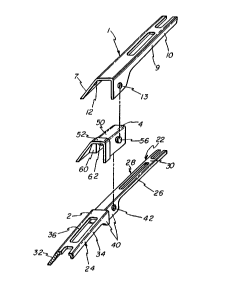
Referring firstly to Figure 1, a pivot joint
comprise~ a first member 1 in the form of the main yoke of
a windscreen wiper blade and a second member 2 in the form
of a secondary yoke, the two yokes 1 and 2 being pivotally
connected together by means of a joint body 4. Both yokes
1 and 2 are preferably constructed from metal sheet
suitably of zinc coated mild steel or stainless steel
while the joint body 4 is moulded from a suitable plastics
material such as acetyle resin or nylon.
The main yoke 1 is of ~ubc?tantially channel
1~71~7
TPC 076 P2 -4-
shaped section at the joint 3, one ~ide 7 of the channel
and the base 8 thereof extending beyond the joint region
and the other side 9 being cut back as at 10 in the region
away from the joint for aerodynamic purpo~es in connection
with the use of the windscreen wiper. At the joint, the
side 9 has the form of a depending ear 11. The side 7
which is not cut away extends at an obtuse angle to the .
channel base 8 while the other side 9 is at right angles : -
thereto. Both channel sides ~7 and 9) of the main yoke 1
have a circular aperture 12 and 13 respectively.
As can best be seen from Figure 4, the second
yoke 2 is also of channel section, but comprises a narrow
part 22 and a wider part 24. The part 22 has both channel
sides 26 and 28 at right angles to the base 30 while the ~ -
wider part 24 has an obtuse side 32 and a right angled -~ -
side 34, both as considered in relation to the base : : :
portion 36. Thus the wider part 24 follows the line of ..
the main yoke 1 while the narrow part 22, which when `.- .
assembled, lies beneath the main yoke 1, does not. The : :
sides 26 and 28 of the narrow part 22 and the side 34 of
the wider part 24 are enlarged in the region of the joint ~
3 to effectively provide depending ear~ 40, suitably :; :
circularly circular apertured at 42.
The joint body 4 is best seen from Figures 2 and
3. It comprises a generally channel shaped member having .-
a main portion 50 and an enlarged end portion 52. The
main portion 50 has an exterior which is complementary to
the interior surface of the main yoke with the addition of --
circular trunnions 54 and 56 which cooperate with circular
., , . ~ :: ; , . . . . . . . ..................... . . .
: , - . ~ . . : . .:
~3~7107
TPC 076 P2 -5-
apertures 12 and 13 respectively of the main yoke 1. It
will be seen that, due to the obtuse angle of the side 7
of the main yoke 1, the trunnion 54 lies at an angle to
the trunnion 56. The shape of the enlarged end portion 52
is intended to continue the exterior shape of the main
yoke 1 as closely as possible and the shoulder 58 between
the main and end portion~ acts to close the open end of
the main yoke 1. The inner surface of the joint body 4 is
generally complementary to the exterior of the ~econdary
yoke 2 and to this end is formed with an internal shoulder
60 which allow~ for the transition between the narrow
portion 22 and the wider portion 24 of secondary yoke.
Two aligned circular trunnions 62 and 64 are provided in
the inner surface of the joint body for cooperation with
the circular apertures 42 in the secondary yoke 2. It is
to be noted that sufficient play must be possible between
the secondary yoke 2 and the joint body 4 to permit the
necessary pivoting between them.
Assembly of the joint will now be described with
particular reference to Figure 4:
Firstly, the joint body 4 is positioned over the
~econdary yoke 2 and i~ pushed down home. This flexes the
sides olf the joint body 4 enabling the trunnions 62 and
64 to pass around the sides 26 and 28 of the secondary
yoke. When the joint body is pushed fully home, the
trunnions 62 and 64 will click into the circular apertures
42 in the secondary yoke 2, thus pivotally securing the
joint body 4 and the secondary yoke together.
Next, the secondary yoke 2 together with the
2.
,: ' . ~ ' , . ` . - `': ':, - ,-: : : '. ., , :
: - . . - . ., . ` :, ~ . :: : : .
13271~7
TPC 076 P2 -6-
attached joint body 4 is offered up into the end of the
main yoke 1. It i~ suggested that the secondary yoke is
offered up at a slant angle ~o that the trunnion 56 first
engage~ in the circular aperture 13 of the main yoke 1.
Then the secondary yoke can be twisted and pushed up so as
to engage the trunnion 54 in the circular aperture 12 of
the main yoke. In this way, a very slight degree of
f lexing of the side 7 of the main yoke can be achieved. ~ - -
This flexing is sufficient because of the obtuse angle of
the side 7. Such flexing is not possible with sides
joining the base portion at right angles. It will of
course be realized that the effectiveness of this
operation relies on the main yoke being made out of
suitable sheet metal, but it has been found that the sheet
metal usually used for the yokes of windscreen wipers
works satisfactorily.
While it is not usually necessary to provide for
detachment of the pivot joints of windscreen wiper blade
harnesses, it is in fact possible to reverse the assembly
procedure by forcing the sides of the main yoke very
slightly apart to release the trunnion 54. The removal
of the joint body from the secondary yoke can be achieved
by pushing the sides of the joint body apart, which i9
relatively easily achieved due to the resilience of the
plastics material of which it is made.
It will be appreciated that various
modifications may be made to the above described
embodiment without departing from the scope of the
invention. For example, if required, the secondary yoke
.. : . .~ . .. .- : . i : ... .
1327~7
TPC 076 P2 -7-
could be made of plastics material instead of from metal
sheet. The angled trunnion 54 of the joint body 4 could
be aligned with the other trunnions of the joint body with
suitable positioning of the aperture 12 in the main yoke
1. It i~ not necessary for the axes of the trunnions 62
and 64 to be aligned with the trunnion 56 and/or 54.
It is also po~sible, by suitable construction of
the joint body 4, to provide the pivot between the joint
body 4 and the main yoke 1 rather than between the joint
body 4 and the secondary yoke 2. The trunnions and the
aperture~ of the non pivoting part~ could be of other than :-
circular if desired. Also the end 52 of the joint body ~ :
could be omitted.
From the above, it will be seen that the : -
described pivot joint enables an easy assembly of the
joint, which can be particularly suitable for assembly by
automatic machinery. No additional parts, such as pivot
pins are required and no forming operations are necessary
once the various parts have been manufactured.
:. ~. . : , . : , . :
,. ~, ~ . , , . . . . ,- .. ,