Note: Descriptions are shown in the official language in which they were submitted.
-` 1327120
APPARATUS FOR MANUFACTURING SPRING UNIT ~ ;
This invention relates to an apparatu~ for
manufacturing a spring unit u~ed for mattresses and the
like.
Japane~e Utility Model Publication No. 35,573/78
discloses an apparatus for manufacturing a spring unit,
in which a plurality of coil springs are formed by
bending a resilient wire. These coil springs form a
spring band having a predetermined thickness, such that
coil springs are arranged side by side in a row and their
side limbs are adjacent to one another. The spring units
further comprise helical wires which interconnect the ~ :
side limbs of the spring band. Those helical wires are
wound around the side limbs by moving the helical wires
15 in the axial direction thereof while the helical wires ~;
are rotated in a manner of a screw in a direction
transverse to the spring band. After the helical wires
are wound to the spring band, the ends of the helical
wires are cut off and then bent by a tool in the end
20 treatment. ;
Where the spring bands are used for mattresses, the
width of the spring bands varie~, depending on the sizes
of the mattres3, that is, whether the mattress i8 used
for a double size, semi-double size or single size bed.
Therefore, it is necessary to vary the feeding length of
the helical wires in accordance with the width of ths :-
~pring bands. Uowevex, in the prior apparatuses for
manufacturing spring units, the feeding length of the
helical wire i8 not automatically controlled in
accordance with the width of the spring band3.
Further, the opposite ends of the helical wires
wound around the spring bands are cut off and bent by the
tool, in the end treatment. The tool is, however,
provided in a fixed position in relation to the width
direction of the spring bands. Therefore, when the width
of the spring bands is changed from that for the double
size to that for the ~emi-double or single ~ize, the
po~ition of the tool i~ deviated from the lateral borders
~ : ~'
1327120
-- 2 --
of the ~pring bands in the width direction thereof, 80
that the ends of the helical wires are no longer treated
by the tool.
Further, the prior art apparatus for making the
spring unit, as disclosed in the publication, is not
provided with any mean~ for forming straight wires into
helical form and automatically feeding these helical
wires to the ~ide limbs of the æpring bands. Therefore,
it iB necessary to perform, as independent steps, a ~tep
of forming helical wires and a step of combining these
helical wires with the spring bands, thus cauæing the
productivity of workers making the spring unit~ to be
reduced.
A first object of the invention is to provide an
$5 apparatus for manufacturing a spring unit, which
apparatus controls the feeding length of helical wires in
accordance with the width of spring bands and allows end
treatment of the helical wires to be performed, even if
the width of the spring bands iæ changed.
A second object of the invention i8 to provide an
apparatus for manufacturing the spring unit, which
apparatus can automatically and continuously perform a
step of forming straight wires into a helical form and a
step of winding the helical wires around the side limbs
of the ~pring bands.
Accordingly, the present invention provides an
apparatus for manufacturing a spring unit, in which coil
springs are formed by bending a resilient wire, said coil
springs being arranged side by side in a row such that
side limbs of each of the coil springs are adjacent to
one another, said coil springs also forming a band of
springs which band has predetermined thickness, and
further in which helical wires are wound around the side
li~hs of each of the coil springs by moving the helical
wires in an axial direction while the helical wires are
rotated in a manner of a screw in a direction tran~verse
to the band of ~prings, whereby the helical wires
: .
~ i .. :
13271~0
interconnect the side limbs of each of the coil springs
in a jaw set attached in line to the apparatus
characterized in that the apparatus compri~es:
means for feeding the helical wires while
controlling a feeding length of the helical wires 80 as
to be substantially equal to a width of the band of
springs, and
two alternate end treatment means, one of which is
provided such that its position is adjustable in a
widthwise direction of the band of springs, for cutting
off and bending forwards ends of the helical wires in a
feeding direction thereof at a po~ition where one end
face of the band of springs is located,
said one end treatment means being movable along the
widthwise direction of the band of springs without
detachment and movement of the jaw set.
With the feeding device and the end treatment
device, it iB possible to control the feeding length of
the helical wire in accordance with the width of the
spring band, to cut off and then to bend the forward end
of the helical wires in the feeding direction.
Consequently, even if the width of the spring bands is -;
changed to that for the double size semi-double size or
single ~ize, it is possible to correspondingly feed a
proper length of helical wire and al~o reliably treat the
forward end of the helical wire. - -~
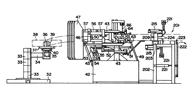
Fig. 1 is a plan view showing a spring unit
accordinq to the present invention;
Fig. 2 i8 a side view showing the spring unit shown
30 in Fig. 1;
:
-- 132712~
-- 4 --
Fig. 3 is a per~pective view showing one of the
spring elements constituting the spring unit shown in
Figs. 1 and 2;
Fig. 4 is a ~ide view showing an apparatus for
manufacturing spring units according to the present
invention;
Fig. 5 i8 a fragmentary view, to an enlarged scale,
showing a portion of the apparatus shown in Fig. 4, other
than a removed portion;
Fig. 6 is a perspective view showing a portion of
the apparatus shown in Fig. 4, other than a removed
portion;
Fig. 7 is a sectional view, to an enlarged scale,
showing a portion of the apparatus shown in Fig. 4;
Fig. 8 is a perspective view showing a portion of
the mechanism shown in Fig. 6, other than a removed ~ -
portion;
Fig. 9a to 9c are fragmentary ~ide view3 showing ~ ~-
three sequential steps in the process of manufacturing
20 spring unit with the apparatus shown in Fig. 4; ~ ~
Fig. 10 is an end view showing a spring band shown ~ ;
in Fig. 3 along with a modified guide;
Fig. 11 is an elevational view showing the entire
apparatus ~hown in Fig. 4;
Fig. 12 is an elevational view showing an end
treatment device shown in Fig. 4;
Fig. 13 is a side view ~howing the end treatment
device shown in Fig. 12;
Fig. 14 is a perspective view showing a portion of
the end treatment device shown in Figs. 12 and 13;
Fig. 15 i8 a 3ectional view showing a slider;
- Fig. 16 is a top plan view showing a bend removal
section;
Fig. 17 is a sectional view showing a feeding
mechanism;
Fig. 18 is a sectional view showing a forming
mechanism and an adjustment mechanism; and
1~ . .. -.
"' ~
. . , . . , . , , .,. . , , I , . . . . . . . . . ` .
1327120
Fig. 19 is a side view showing the adjustment
mechanism and an adjuster.
Figs. 1 and 2 schematically illustrate a spring unit
manufactured by the apparatus according to the present
invention. This spring unit is intended for use in a
spring mattress, but similar units may well be used for
other upholstery, cushions, motor vehicle seats and the
like. The illustrated spring unit comprises a plurality -
of bands of springs. Each band 20 has a shape as shown
in Fig. 3, as will be described later in detail. Bands ~ -~
20 are arranged side by side in rows and are
interconnected by helical wires 21 and 22 extending
transversely of the bands 20. As shown in Fig. 2, two
~ets of helical wires 21 and 22 are used. One set of the
helical wires 21 i8 used for the upper face of the spring
unit. The other set of the helical wires 22 is used for
the lower face of the spring unit. The helical wires 21
and 22 in these two sets are provided at the top and -~
bottom of the spring unit respectively and are staggered ~.'!''~
relative to one another so that they occur alternately. `~
Each band 20 comprises a length of resilient wire
bent 80 a~ to form a plurality of coils or coil springs
23, as shown in Fig. 3, arranged side by side in a row.
~he coil ~pring~ 23 are generally helical in shape and
~uccessive coil ~prings 23 are alternately left- and
right-handed. Each coil spring 23 is joined at one end ~;
to the adjacent coil spring 23 to one side of it and at
the other end to the adjacent coil spring 23 to the other
side of it. Each pair of adjacent coil springs 23 is
interconnected by loop 24 which con~i~ts of part of the
lsngth of wire constituting the pair of coil springs 23.
Loop 24 is shaped approximately as three sides of a
rectangle or as the letter U, having two generally
parallel side limbs 25 and a connector 26 between ~ide
limbs 25. Loop 24 is substantially flat and lies in the
plane of one edge face of the band 20. Side limbs 25
,a~; . ::
, ~'. ' :.
1327~20
-- 6 --
extend in a direction transverse to the length of the
band 20. Connector 26 extends lengthwise of the band 20.
The length of connector 26 is such that side limbs 25 to
which it i~ joined are 80 spaced that two coil springs 23
to which they are joined stand between side limbs 25.
Loops 24 are succe~sively arranged along the opposite
edge faces of band 20 so that there are two groups of
loops 24. More spet:ifically, one group of loops 24 is
arranged along one edge face of band 20. The other group
of loops 24 is arranged along the other edge face of band
20. There is little or no gap between successive loops
24 in each group. Therefore, considering any pair of
successive loops in either group coil springs 27 and 28
are isolated. It will be understood that one side limb
29 of one coil spring 27 is located close to and parallel
with one side limb 30 of the other coil spring 28.
As shown in Fig. 1, helical wires 21 and 22 embrace
a pair of adjacent side limbs 25 of each band 20, i.e. a
pair of adjacent side l~mbs 25 i~ embraced by one helical
wire 21 or 22.
Each coil spring 23 in each band 20 i~ coupled to
the two coil ~prings 23 on either side of it such that ~-
each aoil spring has ~om~ it its turns linked to turns of
the two adjacent coil springs 23. This relation of
coupling i8 ~hown in Fig. 3 (although it is not ~hown in
Fig. 1 for the ~ake of simplicity of the drawings). In
an end view, each band 20 presents a sinuous appearance;
and at no point between one edge and the other edge has
band 20 a thickness much greater than the thicknes~ of
the wire from which the band 20 is formed. Fig. 10 shows
an end Yiew of one band 31. The band 31 having this
shape can therefore be wound into a drum-shaped coil 80
that the drum-shaped coil is substantially parallel with ~;
the longitudinal axes of the band~ 31 and turns of the
drum-shaped coil intersect turns of the adjacent coil.
. .
, ~,,, , , " , , . , .,,, . ,.,, .. , . . , , .,., , . ,, , , . ~ .; ,, , , . . , ~ ,. .. .. . .. . . .
. - :.: ; -, - . - : .. - : . : - - , -,
1327120
.
Figs. 4 to 8 show an apparatus which i~ intended for
use in manufacturing a spring unit using a plurality of
bands 20 which comprise the coil wound in such a shape.
Bands 20 wound into a ring form are laid on suitable
supports ~only a single support being shown in Fig. 4).
The support is provided with base 32. Base 32 has an
upright pillar-like member. A plurality of sleeves 33 is
mounted on the pillar-like member. Each sleeve 33 has an - -
arm 34 extending transversely. Only a single ~leeve 33 ~ - -
with the arm 34 is shown in Fig. 4 for the sake of
simplicity of the drawings. Upright spindle 35 is
mounted on the free end of each arm 34. Spindle 35
supports a rotor. The rotor comprises a pipe-like member ~ -
36 rotatable about spindle 35 and a circular plate 37
mounted under the pipe-like member 36. Spring band 38
rests on the circular plate 37. Fin 39 is provided on an -
upper end portion of pipe-like member 36. Fin 39 engages
with a central portion of the spring band 38. Adjustable
friction pad 40 is provided to hold a lower end portion
of the pipe-like member 36 to prevent the spring band 38
from unwinding in an uncontrolled manner. It will be
understood that this apparatus of manufacture permitE~ a
desired number of spring bands 38 to be mounted for
assembly to obtain a complete spring unit.
A main portion of the apparatus according to the
pre~ent invention is shown in Fig. 4. The main portion ~ -
includes support 42. Frame 43 is secured to support 42.
Frame 43 i8 provided with a plurality of guide grooves 44
(Fig. 5) arranged transversely in a row. Frame-43
includes a flat bottom plate 45 (Fig. 5) having upright
plates 46. Upright plates 46 are parallel to and spaced
apart from one another. Guide pa~sages are defined
between adjacent upright plates 46. Each guide grove 44
has an outwardly open rear end 47. Upright plates 46
(Fig. 4) extend vertically 80 that the spring band 38 can
be readily guided from the support 42 into the apparatus.
'' ,., ~:.
,.
: ,3~ '': ,
. :' .
1327120
-- 8 --
Although not shown in detail, in a modification of
the apparatus, a plurality of bars are provided in lieu
of guide grooves 44. Each spring band 38 is guided by
three or more parallel bars which are spaced apart from
one another. In this modification, bars are positioned
on opposite sides of the spring band 38 and are arranged
in grooves which are defined by the curved spring band 28
and which extend in the longitudinal direction. This
arrangement is apparent when the spring band 38 is viewed
from it~ one end. A typical arrangement of bar~, in
which three bars 48 are used, is shown in Fig. 10.
In Fig. 5, end portions of guide grooves 44 remote
from the band reception end thereof, extend ~traight,
horizontal and parallel and lead to a linking station
which will be described later in detail. Feeding mean~
are provided and serve to engage some of the spring bands
20 and to push them bodily forward, in each cycle of the
operation of the apparatus. The feeding means include
four parallel links 49 and 50, two provided on each side
of the apparatus. The~e link~ 49 and 59 (Fig. 4) are
rotatably supported at their lower end by the support 42
and are coupled, at a point above their lower end, to a
pair of adjustable connecting lin3cs 51. Connecting link~ - -
51 can be reciprocally moved by a pi~ton-and-cylinder
assembly 52 operable by compres~ed air. Assembly 52 i8 .:
mounted on the stationary frame 43 and is coupled to an
arm 53 mounted on a shaft 54. Shaft 54 supports arms 55 ::
at its opposite end portions. These arms 55 are coupled
to the pair of links 50 positioned at their rear side.
Transporter 56 of a wheel type can run along the
stationary frame 43. A~ shown in Fig. 7, the transporter
56 has a pair of parallel bars 57 extending across the
open tops of the guide grooves 44. As shown in Fig. 4,
the transporter 56 i8 coupled to and is reciprocally
moved by a pair of links 50 which are arranged at its
rear side. Bars 57 each support a plurality of fingers
58 (Fig. 7). The~e fingers 58 are hung from the bars 57
.
-
13271~
g .
into the guide grooves 44. A~ shown in Fig. 7, each
finger 58 can swing forwards but cannot swing backwards.
In each operational cycle of the piston-and-cylinder
as~embly 52 (Fig. 4), fingers 58 (Fig. 7) engage the
~pring bands 20 and push them forwards by a distance
corresponding to the width of two coils and then return
and can engage the spring bands 20 again at a position
thereof spaced apart a distance corre~ponding to the
width of two coils from the position at which fingers 58
have engage the spring bands 20 ~Fig. 7).
Transver~al bar 59 (Fig.6) extends between the pair
of links 49 arranged at a forward side and carries a
plurality of pawls 60. Of these pawls 60, each pair is
associated with each spring band 20. One of the pair of
pawls 60 is positioned upwardly of the spring band 20 and
the other is positioned downwardly of the spring band 20.
Pawls 60 have an identical shape, as typically shown in
Fig. 6. As shown in Fig. 6, the pawl 60 has a front side
portion 61, which can engage one spring band 20 and pull
the spring band 2 forwards a~ the pawl 60 itself is moved ;-
forwards, and a rear side portion 62, which i~ inclined
as the rear side portion 62 goes away from the associated
spring band 20. Thus, as the pawl 60 is moved backwards, -~
it is disengaged from the associated spring band 20. As
~hown in Fig. 7/ the fingers 58 are arranged 80 as to - ;
push the spring band~ 20 forwards by a distance
corresponding to the width of two coils in one cycle of
the operation of the apparatus. At the linking station
shown in Fig. 5, there are two ~ets of jaws 63 and 64
which constitute gra6ping means. One set of jaws 63 i8
arranged below the spring bands 2 and the other set of ~ -
jaws 64 is arranged above the ~pring band~3 20. Lower and
upper jaws 63 and 64 are vertically spaced apart by a
distance substantially corresponding to the thickness of
35 coil springs 23 and also are spaced apart horizontally by
a distance substantially corresponding to the diameter of
~- the coil springs 23. Each set of jaws 63 and 64
'',":-
~ .
~ .
~ : .
. .
327120
-- 10 --
comprises, pairs of jaws corresponding in number to thenumber of spring ~ands 20. Each pair of jaws 63 and 64
act on the associated spring band 20. One jaw 65 of each
pair is stationary and extends in a generally vertical
5 direction, as shown in detail in Fig. 6. The other jaw
66 i8 pivotally connected to the fixed jaw 65, in a
considerably large angle range, by horizontal pivotal pin
67 which extends transverse to the direction of feeding
of the spring bands 20. Although only one lower jaw set
63 is shown in Fig. 6, the remaining lower jaw set 63 is
the same as the illustrated one. The upper jaw sets 64
are also like the lower ones except that they are
inverted. Each jaw pair 63 and 64 is controlled for
operation by associated piston-and-cylinder assembly 68
operable by compressed air. The cylinder of the assembly
68 is pivotally connected to the frame 43 and its piston
is coupled so that extension 69 of jaw 66 extending
beyond pivotal pin 67 is pivotable. Inclined plate 41
(Fig. 5) is mounted on the rear end of the stationary jaw
65 (Fig. 6) of each lower jaw set 63 80 that the edges of
the spring band 20 can move on the jaws 63 without the
edges of the spring band 20 being caught by the jaws 63 -
(Fig. 5).
When the pairs of jaws in the lower and upper jaw
~ets 63 and 64 are opened, the feeding meana are operated
to feed the spring bande 20 f orward as described above.
When the forward movement of the spring bands 20 i~ ~ .
completed, the pairs of side limbs 25 of the loops 24
have passed over the backs of the stationary jaws 65
(Fig. 6) and then snapped into the open mouths of the
jaw~ 63 and 64 (Fig. 5). While some pairs of side limbs
25 are urged against the inner faces of the adjacent
stationary jaws 65 (Fig. 6), almQst all side limbs 25
move a short distance beyond the stationary jaws 65 but
remain in the open mouths of the jaws 63 and 64 (Fig. 5).
Next, movable jaw~ 66 (Fig. 6) are then pivc~ted backwards `
against the feeding direction of the spring bands 20
132712~
-- 11 -- .
toward stationary jaws 65. Movable jaws 66 carry the
pairs of ~ide limbs 25 backwards to stationary jaws 65
and accurately position the side limbs 25. The distance
covered by side limbs 25 is 80 small that the spring
5 bands 20 ( Fig. 5) are not moved bodily but are only
flexed somewhat by the movement of the side limbs 25.
In Fig. 6, the jaw 66 which has pivoted is shown at
its intermediate position between its perfectly open
position and its perfectly closed position. The cycle of
10 operations described above is illustrated in Figs. 9a,
9b, and 9c. Fig. 9a shows a state in which the haws 63
and 64 are open and the spring bands 20 have been moved
forward by the fingers 58. Fig. 9b shows a state in
which the fingers 58 are in the foremost positions and
15 the pairs of side limbs 25 of the spring band 20 are in
the jaws 63 and 64. Fig. 9c shows a state in which the
jaws 63 and 64 are closed and side limbs 25 of the spring -~
band 20 are pulled slightly rearwardly, and also a state
in which the fingers 58 are returned to the rear-most
20 positions to be ready for pushing the spring bands 20
forward if the jaws 63 and 64 are opened.
Reces~ 70 in Fig. 6 is defined in the inner faces of
each pair of jaws 65 and 66, that is, the faces which
meet when the jaws 65 and 66 are closed. Rece~EI 70 form~
25 a tubular opening having two open ends for receiving a
pair of side limbs 25 of the spring band 20 in Fig. 5.
Further in Fig. 6, the wall defining the tubular opening
has some groove~i 71. These grocves 71 serve to define a
continuou~ helix when the iaws 65 and 66 are closed. A
30 slight gap remains between the jaws 65 and 66 of each
pair 80 that a portion of helical wire 21 ~uccessively
linked to side limbs 25 of the spring band 20 can be
received into the gap. Such helical groove 71 receive~3
one helical wire 21 for connecting the side limbs 25 of
35 on~ pair as ~hown in Figs. 1 and 2 and hence links
together adjacent spring bands 20. E~elical wire 21 is
introduced, in a manner of a screw, into the helical
,.: . : ~ :-: .; : ., : . , - .... . . , ~ ., : .
13271~0
- 12 -
groove 71 from one end of the jaws 65 and 66 of each pair
immediately after the jaws 65 and 66 are closed. Each of
the two helical wires 21 is rotated and moved axially by
the mechanism shown in Fig. 6. This mechani~m i~ mounted
on the stationary frame 43 such that the mechanism faces
the device shown in Fig. 4. The mechanism shown in Fig.
6 comprises a pair of parallel rollers 72 having
respective annular grooves. Rollers 72 can be rotated
continuously in the same direction by a motor (not
shown). Third roller 73 also having annular grooves i8
mounted in ~upport means 74 which is pivotally coupled to
frame 43 (Fig. 4) at a position 75 (Fig. 6). Manual ;
lever 76, which is pivotally connected to the frame 43
(Fig. 4) at the lower end portion thereof, supports arms -~
77 (Fig. 6). These arms 77 centre the manual lever 76 in
a slot provided as shown in Fig. 6. Lever 76 is urged to
the illustrated position by a coil spring 78 and is
controlled by an adjustable stopper 79. The manual lever
76 i8 pulled downwards by the operator of the apparatus
and i~ released after inserting one end of one helical
wire 21 between rollers 72 and 73. As a consequence, the
helical wire 21 i8 pulled in the lengthwise direction
while it i8 rotated in the condition that the helical
wire 21 i8 held between the rollers 72 and 73. The
distance covered by the helical wire 21 i8 held between
the rollers 72 and 73. ~he distance covered by the
helical wire 21 is restricted by a stopper which is
~ecured to the apparatus on the ~ide opposite to the
feeding mechanism described above.
After two helical wires 21 have been linked to the
spring band~ 20, the end portions of the spring band 20,
which project a short way beyond the sets of jaws 65 and
66, are cut off. The newly formed ends of the helical
wires 21, close to the jaws 65 and 66 which are
positioned at the end side, are bent inwards. The newly
formed ends are thus wound around the adjacent portion of
the spring band 20 which is positioned at the end side.
. :'.'
- 1 ~ 2;~
-- 13 --
As a result, the loop 24 i9 formed. This cutting and
bending of the end of each helical wire 21 i8 performed
by a fixed tool 80 (Figs. 6, 8, and 11). Tool 80
constitutes a first end treatment device which is
5 pivotally connected to a stationary member 81 ( Fig . 8) at
the adjacent end of the jaw pair by a flat pivot pin 82 ~-
extending parallel with the feeding direction of the
spring bands 20. The first end treatment device, as
shown in Fig. ll, comprises a plurality of pairs of tools
10 80, each pair being vertically spaced apart from one
another by the same distance as the thickness of the
spring bands 20. The pairæ of too} 80 also are spaced
apart a predetermined distance in the feeding direction
of the helical wire 21. More specifically, the vertical
15 set of rearward tools 80 which are po~itioned at the
inlet for the helical wire 21 in the feeding direction
and the pair of forward tools 80 at a forward position
are spac:ed apart from one another by a distance
substantially equal to the width of a double-sized bed
20 u~ing the spring bands 20.
In Fig. 6, the fixed tool 80 i~ shown separated from
the adjacent jaw 65. Stationary cutter block 83 shown in
Fig. 8 is bonded to the stationary member 81. Helical
wire 84 is also shown in Fig. 8. In use, the fixed tool
25 80 i~ pivoted in the direction of an arrow in Fig. 8 by a
piston-ànd-cylinder assembly operable by compressed air,
piston 85 of which (Fig. 6) is coupled to extension 86 of
the tool 80 beyond the flat pivot pin 82 (Fig.8) .
Upright lug 87 urges t~e helical wire 84 against the
30 cutter block 83 to cut off the end of the helical wire 84
and bend the cut end towards the adjacent band until the
cut end forms a closed or substantially closed loop.
After the cutting and bending, the tools 8Q are
returned to their initial positions, the jaws 65 and 66
35 ~Fig. 6) are opened to release the helical wires 84 (Fig.
8), and the feeding means are again operated to move the
bands 20 (Fig. 5) and any completed part of the spring
'
,
:
'~ '
. :. . - ~ . .: : . . ~
1327120
- 14 -
unit forward. Links 49 are pivoted about their lower
ends, so that pawls 60 are raised as they pull the linked
bands 20 forward, thereby also raising the bands 20.
Thus, the ~ands 20 are made to be readily separable from
the lower set of the jaws 63. the lower of the bands 20
from the jaws 63 is assisted by transverse bars 88 which
are disposed below the bands 20 and are secured to the
links 49 through brackets 89. The upward movement of the
bands 29 tends to o~struct rather than assist the passing
of the bands 20 over the upper sets of jaws 64. To
overcome this difficulty, a stationary bar 90 which
extends parallel to the transverse bars 88 i6 mounted
above the bands 20 between the jaws (63,64) and the links
49.
When the bands 20 are to be used for a semi-double
or single-sized bed, the forward end of the helical wire
21 in the feeding direction cannot be cut off and bent by
the forward-side tools 80 of the first end treatment
device shown in Fig. 11. In such a case, the treatment
is performed by a eecond end treatment device 201
disposed in the feeding direction of the spring bands 38,
as ~hown in Fig. 4. Second end treatment device 201 has
a support 202. Guide rail 203 is provided on support 202
such that guide rail 203 extends horizontally in the
widthwise direction of the ~pring bands 38, as shown in
Figs. 12 to 15. Slider 204, as shown in Fig. 14, is
slidably mounted on the guide rail 203. Slides 204, as
shown in Fig. 15, comprises a bottom plate 205, opposite
side plates 206, and a top plate 207. These plates 205-
207 completely surround the outer periphery of the guiderail 203. When screws 208 securing top plate 207 to side
plates 206 are loosened, the slider 204 can be moved
along the guide rail 203.
As shown in Fig. 13, there are upper and lower sets
of jaws 211 and 212. As shown in Fig. 12, they are
arranged on the slider 204 via mounting member 209. Jaws
211 and 212 of Figs. 13 and 14 have the same structure as
`
- 1327120
- 15 -
jaws 63 and 64 of Figs. 4 - 11 provided in the main part
of the apparatus. More specifically, as shown in Fig.
14, jaw 213 is fixed, while jaw 214 is pivotable about
pin 220. Jaw 214 can be driven by a first piston-and-
cylinder assembly 215.
Further, mounting member 209 is provided with a pair
of upper and lower movable tools 216 having the same
structure as the fixed tools 80 shown in Fig. 8. Each
movable tool 216 is pivoted by pin 218 to movable member
217, to which cutter block 219 is secured. Further, each
movable tool 216 of the pair i8 moved in the direction of
an arrow shown in Fig. 14 by a second piston-and-cylinder
assembly 221 (Fig. 13). When movable tools 216 are
dri~en as shown in Fig. 14, like the case of Fig. 8, the
helical wire 84 is urged against the cutter block 219 and
its end i8 cut off. Then the cut end is bent toward the
adjacent band until the cut end forms a closed or
substantially closed loop. -
When the size of the spring bands 38 i changed from
that for the double size to that for the semi-double size
or the single-sized bed, the slider 204 is moved in Figs.
12 and 14 in accordance with the change in the width of
the bands 38 to a position at which the movable toola
216, shown only in Fig. 14, face the forward edge face of
the spring band~ 38 in the widthwise direction thereof.
The end of the helical wire 84 thus is cut off and bent
at the forward end face of the spring bands 38 in the
widthwise direction thereof.
In this operation shown in Fig. 13, the first
piston-and-cylinder a~sembly 215 is operated to close
upper and lower jaws 211 and 212. Next, the second
piston-and-cylinder assembly 221 i6 operated to drive
movable tools 216 (Fig. 14 only) and then the end of the
helical wire 84 is cut off and bent. Thereafter, the
35 first piston-and-cylinder assembly 215 is operated to -~
open the upper and lower jaws 211 and 212 80 as to
release the helical wire B4. As a result, the third
~327120
- 16 -
piston-and-cylinder assembly 221 shown in Fig. 13 and
provided on support 202 i8 operated to rotate feed rod
222 (Fig. 4) about the lower end thereof in the direction
of the arrow in Fig. 4. Con~equently, feed pawl 223
provided on the upper end of the feed rod 222 engages the
spring bands 38 and feeds them to the next stage. Second
end treatment device 201 is synchronized to the first end
treatment device as noted above. In Figs. 12 to 14,
guide members 224 are vertically spaced apart by a
distance slightly greater than the thickne~s of the
spring bands 38. These guide members 224 guide the
forward end fa~e of the spring bands 38 in the widthwise
direction thereof.
The various processes described above can be started
intermittently by the operator of the apparatu~, and the
operator can check the results of previous operation~
prior to the ~tart of the next process. Alternatively,
it i~ possible to permit some or all of the proce~ses
described above to be started automatically at the end of
a previous process.
~ he feeding means noted above comprises the fingers
58 (Figs. 7, 9a, and 9c) and the pawls 60 (Fig. ~1) set
to engage the bands 20. If it i~ found that the
apparatus can be operated satisfactorily by omitting some - -
of these parts, the feeding mean~ may be formed by
omitting ~uch part~. - -
Straight wires 21a and 22a are reformed by the
reforming device 101 (Fig. 11) and are fed between the
rollers 72 and 73 shown in Fig. 6. A~ shown in Fig. 11,
the reforming device 101 comprises feeding mechanism 102
and forming mechanism 103. Feeding mechani~m 102
includes a pair of bend removal sections 104 having a
pair of upper and lower roller groups disposed for
removing bends of the straight wires 2la and 22a, a pair
of strain removal sections 105 for removing strain from
the straight wires 21a and 22a, and a drive section 10~
for feeding the ~traight wires 21a and 22a to the forming
' .
: .~
. ~ :
1327120
- 17 -
mechanism 103. As shown in Fig. 16, encoder 251 is
coupled via gear train 252 to one roller 250 in the
roller groups of the bend removal section 104 and
converts the rotation numbers of roller 250 into an
electric signal. The electric signal is supplied to a
counter (not shown) in which the number of rotations is
counted. The amount of feed of the straight wires 2la
and 22a is calculated by the rotation nu~ber of the
roller 250. Therefore, once a count of the counter is0 preset, the feeding of the straight wires 21a and 22a is
when a predetermined length of the straight wires
21a and 22a has been fed. In this way, the helical wires
21 and 22 can be fed in length corresponding to the
length of the spring unit. The length depends on whether
the spring unit is for single-sized, semi-double size or
double-sized beds. It is to be understood that encoder
251 and roller 250 constitute feeding means for measuring
and controlling the length of the straight wires 2la and
22a to be supplied. Drive section 106 ~Fig. 11) includes
a housing 107 as shown in Fig. 17. First shaft lO~,
second shaft 109, and third shaft 111 are rotatably
mounted one above another in the mentioned order between
parallel and spaced-apart side plates of the housing 107.
Housing 107 is provided with a first motor 112 disposed
in an upper portion and a second motor 113 disposed in a
lower portion. Fir~t sprocket 114 is fitted on the
output shaft of the first motor 112, and a first chain
116 is passed around the first sprocket 114 and a second
~procket 115 fitted on one end of the first shaft 108.
First gear 112a is fitted on one end of the first shaft
108 and i8 meshed with a second gear 113a fitted on one
end of the second shaft 109. First and second feed
rollers 117 and 118 in rolling contact with each other
are fitted on the other ends of respective first and
second shafts 108 and lO9. The outer peripheries of the
feed rollers 117 and 118 have grooves ll9, into which the
straight wire 21a i5 introduced. Therefore, when the
:
.
':
- 1327120
- 18 -
first motor 112 is operated, the ~ir~t and second shafts
108 and 109 are rotated in opposite direations to feed
the straight wire 21a clamped between the pair of feed
rollers 117 and 118.
Third gear 121 and third feed roller 122 are
rotatably mounted on the other end of the second shaft
109. Gear 121 and feed roller 122 are integrally coupled
together. Third sprocket 123 is fitted on the output
shaft of the second motor 113. Second chain 125 is
passed around the third sprocket 123 and a fourth
sprocket 124 fitted on one end of the third shaft 111.
Fourth gear 126 meshing with the third gear 121 and a
fourth feed roller 127 in rolling contact with the third
feed roller 122 are fitted on the other end of the third ~-
shaft 111. Third feed roller 122 and fourth roller 127
have grooves 128 formed in their outer peripheries. The ~
other 3traight wire 22a can be introduced into the -
groove~ 128. Therefore, when the third shaft 111 i8
driven by the second motor 113, third and fourth rollers
122 and 127 are rotated-in oppo~ite directions by the
meshing of the third and fourth hears 121 and 126,
irrespective of the rotational state of the second shaft
109. Thus, the other ~traight wire 22a introduced
between the feed rollers 122 and 127 is fed in the same
direction as the ~traight wire 2la.
The pair of straight wires 21a and 22a fed by the
feeding mechani~m 102, which has the structure as ~ -
described above in regard to Fig. 11, i8 each fed to the
forming mechanism 103. Forming mechaniem 103, as shown
in Fig. 18, has guides 131. Each guide 131 has a tapered --~
end 132. Tapered ends 132 are disposed such that they
face outlets of the feeding mechanism 102 from which the
pair of straight wire~ 21a and 22a are fed out. Each
guide 131 ha~ coaxial small and large diameter bores 133
and 134 extending axially and communicating with each
other. Small bore hole 133 has an inner di~meter ~-~
slightly greater than the diameter of the straight wires ~
: .
''' "
' .-:
': ' ' " :~ ': : ' '' . ' ' ' .' '' ' ' . ' '. '`
1327120
-- 19 --
2la and 22a. Forming rod 135 i~ inserted into the large
diameter bore 134 from one end thereof and i9 ~ecured in
position by a screw 136. Forming rod 135 hae one end
portion formed with a straight groove 137 communicating
with the small bore hole 133 or the guide 131 and the
other end portion formed with a helical groove 138 having
one end communicating with the straight groove 137.
Collar 139 is rotatably mounted on the other end portion
of the rod 13S formed with the helical groove 138.
Detachment of the collar 139 from the forming rod 135 is
prevented by a guide cylinder 142 having oppo~ite end
flanges 141 and also having the same internal diameter as
the forming rod 135. Guide cylinder 142 i8 ~ecured to
the reforming device 101. Thus, the straight wires 21a
and 22a fed to guide 131 of the forming mechanism 103 are
formed into the helical wire 21 and 22 noted above as
they pass through the helical groove 138 of the forming
rod 135.
Helical wires 21 and 22 are fed into an adjustment
mechanism 143. Adjustment mechanism 143 ha~ a base 144
which is securely provided on the reforming device 101 a~
shown in Fig. 18. Base 144 has a slide groove 145
extending in the feeding direction of the helical wires
21 and 22. In the slide groove 145, and adjuster 146 iB ~.
slidable and capable of being secured in a given position
by a set screw 147 as shown in Fig. 19. Further, the
base 144 i~ provided with an adjustment screw 148 (Fig.
18) for adjusting the position of the adjuster 146.
Adju~ter 146 has a mounting hole 149 shown in both Figs.
18 and 19. Pitch shaft 152, which has a helical groove
151 (Fig.18) at the same pitch as the helical wires 21
and 22, is inserted in the mounting hole 149 and secured
by a set screw 150.
~elical wires 21 and 22 are formed by the forming
mechanism 103 and pass the helical groove 151 of the
pitch shaft 152. Thus, by changing the position of the
helical groove 151 in the direction of the arrow shown in
; -.~
. ~ . . . .
1~712~
- 20 -
Fig. 18 due to the di~placement of the pitch shaft ~52 in
the direction of the same arrow, the pitch of the helical
wires 21 and 22 is changed as the wires 21 and 22 pass
through the helical groove 151. Helical wires 21 and 22
formed by the forming mechanism 103 have a pitch which is
varied slightly depending on the material of the wire
(21,22) or other factors. The pitch is therefore
adjusted by the pitch adjustment mechani~m 143.
Helical wires 21 and 22 with the pitch thereof
having been adjusted by the pitch adjustment mechanism
143 are passed through cylindrical guides 153 to be fed
between the rollers 72 and 73 as shown in Fig. 6. Roller -
72, as shown in Fig. 6, is rotated by an endless bslt 155
(Fig. 11) driven by a motor 154 (Fig.11). Helical wires
21 and 22 that have been supplied between the pair of the
rollers 72 and 73 (Fig. 6) disposed one above another are
fed to the side limbs 25 of the bands 20 ~Fig. 11) as
they are rotated with the roller 72 (Fig. 6). Thus, the
helical wires 21 and 22 (Figs. 1 and 2) link side li~h~
25 ~Fig. 3) of the bands 20 ~Fig. 1).
First and second motors 112 and 113 shown in Fig. 17
are stopped by a signal from the counter connected to
encoder 251 (Fig. 16). When the ~traight wires 21a and
22a (Fig. 11) are fed to an amount of a predetermined
length in accordance with the width of the bands 20,
first and second motors 112 and 113 are stopped 80 that ;~
the straight wires 21a and 22a will no longer be fed.
Thus, the apparatus for manufacturing a spring unit
according to the invention is very useful for readily -
manufacturing mattresses having different size~ and can
also improve productivity.
Although the pre~ent invention has been
described in some detail by way of example for purpose~ -
of clarity and understanding, it will be apparent that
35 certain change~ and modifications may be practised within ~ -
the scope of the appended claim~.
. ~: - -': . :.
. .
,~ ; . "''':'`,''' '