Note: Descriptions are shown in the official language in which they were submitted.
: ::
132719~ :
TOP HEAD DRIVE ASSEMBLY FOR
EARTH DRILLING MACHINE AND COMPONENTS THEREOF ;
BACKGROUND OF THE INVENTION ~ -
This invention relates to improvements to a
top head drive assembly for an earth drilling machine
~uch as a machine for drilling oil or water wells. -~-
High speed, automatic operation is becoming ~ ;
increasingly important for a wide range of earth drilling
machines. High speed operation reduces the drilling --
time and automatic operation reduces the number of
drillers required at the drilling cite. Both of these
factors substantially reduce drilling costs, and
automatic operation provides the added advantage of
reduced in~ury to drillers.
- Another important factor in drilling machines
is that significant advantages can be obtained by mini~
mizing the overall height of the drilling machine and
in particular the drilling mast. By reducing the height -~
of the drilling machine, the weight of the drilling
machine and its susceptibility to wind loading problems
are both reduced. These factors can result in important
savings in the size and cost of the drilling machine,
along with important advantages in terms of increased ;
mobility, lower moving costs and fa~ter rig-up and
rig-down times.
:~ ,. . .
,~ ~ - . -. .
, ~ . , .
,~
--2--
132719~ -
It is an object of the present invention to
provide an improved top head drive assembly and com-
ponents for a top head drive assembly which minimize
the height of the top head drive assembly and which
cooperate to facilitate high speed, remote controlled
automatic drilling operations.
SUMMARY OF THE INVENTION ;
According to a first aspect of this invention, -
a top head drive assembly for an earth drilling machine
of the type comprising a load beam, means for gulding
the load beam for movement along a mast, a ~uill
supported on the load beam, and means for rotating the
quill, is provided with a pair of spaced support rails
suspended from the load beam. A wrench assembly com- ~`
prising an upper clamp adapted to clamp an upper tubular,
a lower clamp adapted to clamp a lower tubular and means
coupled between the upper and lower clamps for rotating
one with respect to the other to torque one of the upper
and lower tubulars with respect to the other is guided
along support rails under the load beam. Means are
provided for moving the wrench assembly along the rails
and a tubular support assembly is provided beneath the
wrench assembly. Thi8 tubular support assembly comprises
a ~upport beam, means mounted on the support beam for
releasably supporting a tubular which may support a
string of tubulars in the well bore, means for controlling
the support means to selectively release and engage the ~ -
tubular, means for pivotably mounting the tubular support
a#sembly from the rails, and means for pivoting the
tubular support assembly between an op~rative position
aligned with an axis defined by the quill under the
wrench assembly and a storage position laterally offset
from the wrench assembly.
.
.,
l -2-
.~ .
327195
;.
This aspect of the invention provides important
advantages in that both the wrench assembly and the `
tubular support assembly are supported by the load beam
to move with the load beam to provide a compact unit.
Preferably, the tubular support a~embly can be locked
in the operative position such that the tubular support
assembly will center a supported tubular properly for
insertion into the wrench assembly.
According to a second aspect of this invention, ~
a tubular support assembly, which may for example be ~;
used in the invention described above, comprises a support
beam having first and ~econd ends and an opening passing
through the beam intermediate of the ends. A bowl is ;~
positioned in the opening and secured to the support
beam. This bowl defines an inner surface which forms a
larger diameter in an upper region and a smaller diameter
in a lower region. At least a pair of inserts are shaped ~ :
to fit within the bowl to support a down hole tubular.
Mean~ are provided for moving the inserts between an --
. . ...
upper position in which the inserts are positioned to
allow the down hole tubular to be inserted in and removed
from the bowl opening, and a lower position, in which
the inserts are positioned in the retainer opening to ~-
support the down hole tubular. The ends of the support
beam are rigidly supported on the top head drive assembly `` ~`
such that the opening is held in alignment with a drilling
axis defined by the top head drive assembly. ;
According to a third aspect of this invention,
an apparatus for ~upporting a down hole tubular beneath
a top head drive assembly, which may be of the type
described above, is provided with means for centering~`a
down hole tubular. Preferably, the centering means
includes a plurality of centering elements, mean~ for
pivotably mounting the centering elements under the
apparatus such that the centering elements are movable "~
to approach and move away from a drilling axis, and
~ ~3~
i ~ ` ,
. -, . ',
~ 4- 1~2719 ~
means for moving the centering elements toward the
drilling axis to center a down hole tubular under the
apparatus. This aspect of the invention positively
centers tubulars such as crooXed or bent drill pipe for
insertion into the tubular support apparatus.
According to a fourth aspect of this -
invention, a support or load beam is provided which may
be used in either the top head drive assembly or the
tubular support apparatus. This beam comprises a
support member adapted to support a load bearing member
such as the quill of the top head drive assembly or the
upper joint of a drill string. A box section is dis-
posed around the support member, and this box section
tapers in width from the support member toward each
end. First and second diagonal braces are disposed in
the box section, each tapering in width from a wider
upper end which abuts the support member to a narrower
lower end situated adjacent to a lower portion of a
respective one of the ends of the box section. A
plurality of support elements are provided, each posi-
tioned to surround the box section adjacent to a
re pective end to resist any increase in width of the
box ~iection. The braces are positioned such that down-
ward forces on the support member tend to increase the
width of the box section adjacent the support elements.
In this way an extremely rigid beam is pr~vided which
does not rely entirely on welds for strength.
It will become apparent in the following
' description of the presently preferred embodiment that
, the various aspects of this invention cooperate to
,1 provide a top head drive assembly which is extremely
compact in overall height and which i~ well-suited to
automatic high speed operation. The centering means
.~ "~ -
~ -4- -
: ':
-5~ 1 3 2 7 1 9~
centers a crooked tubular for quick makeup; the tubular
support assembly supports the tubular quickly, without
requiring that any threaded coupling be made, and it
rigidly supports the tubular or drill string or casing
string on the drilling axis. The movable wrench assembly
can readily and remotely be moved into the desired axial ;
position so as to align itself with a threaded joint to
supply the desired make up or break out torque. The
entire assembly can readily be adapted for use with
either casing or drill pipe. In a particularly preferred
form of the invention, the top head drive assembly can :
be eguipped with an apparatus for engaging the guill of
the top head drive assembly with an interior portion of
a tubular in order to allow the guill to rotate the
tubular as desired. ~
~ .: ,. ~ ' :: .
': ~-' '
The invention itself, together with further
object~ and attendant;advantages, will best be understood
by reference to the following detailed description,
taken in conjunction with the accompanying drawings.
: ' ' .
BRIEF DESCRIPTION OF THE DRAWINGS -
Figure 1 i8 a front elevational view of a ~ -
portion of a drilling machine which incorporates a top
head drive assembly that incorporates presently preferred
embodiments of this invention.
Figure 2 is a bottom view of a centering device `~
taken along line 2-2 of Figure 1.
Figure 3 is a side view taken along line 3-3
of Figure 2.
Figure 4 is a sectional view taken along line
, 4-4 of Figure 3.
I Figure 5 is a bottom view corresponding to
, Figure 2 showing the centering device with the centering
1 elements in inner positions.
-5-
,:
.,, ~ . .
., , :
, . ! . ' ' ' .
` -6- 132719~
Figure 6 is perspective view of an alternate -
embodiment of the centering device of this invention.
Figure 7 is a perspective view of another
alternate embodiment of the centering device of this
invention.
Figure 8 is a sectional view taken along line
8-8 of Figure 1.
Figure 9 is a sectional view taken along line
9-9 of Figure 8.
Figure 9a i~ a view similar to Figure 9
showing the inserts in a raised position.
Figure 10 is a sectional view taken along
line 10-10 of Figure 8.
Figure 11 is a top view of an alternate
embodiment of the tubular support assembly of this
invention.
Figure 12 is a sectional view taken along
line 12-12 of Eigure 11.
Figure 13 i8 a sectional view taken along ~ -
line 13-13 of Figure 1 showing a preferred embodiment -
of the wrench assembly of this invention.
Figure 14 is a view similar to Figure 13
showing the wrench as~embly with the upper wrench in a
rotated position.
Figure 15 is a sectional view taken along
line 15-15 of Figure 13.
Figure 16 is a sectional view taken along
line 16-16 of Figure 13.
Figure 17 is a sectional view in the plane of -
Figure 9 showing the embodiment of Fiyure 9 in use.
DETAILED DESCRIPTION OF THE
~ PRESENTLY PREFERRED EMBODIMENTS
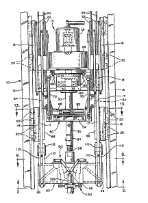
¦ Turning now to the drawings, Figure 1 ~hows
an elevational view of a drilling machine 10 that includes
a mast 12 and a top head drive assembly 14. The top
-6- -
. :
'' . .
`` 132719~
head drive assembly 14 includes a load beam 16 which is
secured at each end to a pair of drive tracking assem-
blies 18. The top head drive tracking assemblies 18
are provided with rollers 20 which guide the top head
drive assembly 14 for move~ent along channels on the
mast legs 12. Two sets of sheaves 22 are secured to
the load beam 16, and these sheaves 22 suspend the top
head drive assembly 14 from a cable 24. This cable 24 -
operates to move the top head drive assembly 14 along -
the length of the mast 12. ~:
The load beam 16 also supports a trans-
mission 26 and a pair of electric motors 28. The
motors 28 and the transmission 26 cooperate to make up -
a means for rotating a quill 30 which is rotatably
supported in the load beam 16. The quill 30 defines a
lower threaded end which can be threadedly engaged with
a string of tubulars which may for example include an
upper tubular 32 and lower tubular 34. As used herein
the term "tubular" is used to signify a tubular element
used in a down hole drilling or well service operation,
and i6 meant to include the full range of drill pipe, `
drill casing, adapter subs, blowout preventer subs and
the like. In general, an entire string of tubulars
will extend along a drilling axis 36, and the quill 30
is used to support and rotate the tubulars about the
drilling axis 36. ` ~
The features of the drilling machine 10 des- -
cribed above are well-known to those skilled in the art `
and do not therefore form any part of this invention. -
These details have been provided merely to clarify the
environment of the present invention. U.S. Patent
4,314,611, assigned to the assignee of the present
invention, discloses one prior art top head drive
assembly incorporating these features.
.
3 ~ 7
,~ .
1327~9~
According to this invention, the top head
drive assembly 14 is provided with a wrench assembly
50. This wrench assembly 50 as shown in Figures 13-16
includes an upper clamp 52 and a lower clamp 54. Each
of the clamps 52, 54 includes an opposed pair of jaws ~:
56, each of which is provided with a pair of rotatable
tubular gripping inserts 58. The jaws 56 are positioned
by cramping cylinders 60 which move the jaws 56 along :
respective jaw guides 62.
The details of construction of the clamps 52,
54 are largely conventional. For example, the structure : ~ :
of the inserts 58 i~ described in detail in U.S. Patent .
4,475,607, assigned to the assignee of the present inven~
tion. The jaw guides 62 can be formed as described in ~
U.S. Patent 4,303,270, also assigned to the assignee of
this invention.
The lower clamp 54 defines a pair of opposed
wrench guides 64 which are positioned to slide in wrench
guide tracks 66 mounted on the load bars 17 which support
the tubular support beam 92. These wrench guide tracks
66 are diametrically opposed with respect to the drilling .
axis 36, and they guide the wrench assembly 50 in axial
movement parallel to the drilling axis 36 while resisting
any tendency o the wrench assembly 50 to rotate with : :
respect to the top head drive assembly 14. A pair of :
rotating cylinders 68 are mounted between the upper and
lower clamps 52, 54. These rotating cylinders 68 operate :~
to rotat~ the upper clamp 52 by about 30 with respect .
to the lower clamp 54 between the two extreme positions
shown in Figures 13 and 14. Thus, the rotating cylinder~
68 supply a defined torque to the upper clamp 52 and
can be used to make up or break out a threaded connection.
-8-
-, .
.
9 132719~
::: :.,
The entire wrench assembly 50 can be moved
axially along the wrench guide tracks 66 by means of
positioning cylinders 70 (Figure 1). These positioning `- .
cylinders 70 are mounted between the wrench assembly 50
and the load beam 16, and can be extended and retracted
in order to position the wrench assembly 50 appropriately
such that the upper clamp 52 is positioned to engage ::
the upper tubular 32 and the lower clamp 54 is positioned.~
to engage the lower tubular 34. .:
In use, the positioning cylinders 70 are used
to position the wrench assembly 50 appropriately with i:
respect to the threaded joint which is to be made up or ~
broken out (Figure 16). Then the upper and lower clamps :-
52, 54 are closed on the tubulars 32, 34 by supplying - .:
pressurized hydraulic fluid to the clamping cylinders .` `
60. At this point the upper and lower clamps 52, 54 :
are positively engaged with respect to the tubulars 32,
34, respectively (Figure 16). Then the rotating cylin~
ders 68 are activated in order to rotate the upper clamp :
52 with re~pect to the lower clamp 54 in order to supply
the desired make up or break out torque. ..
The function performed by the wrench assembly
50 i~ similar in some respects to that performed by the
self-centering tongs described in U.S. Patent 4,gO3,666,
assigned to the a~signee of the present invention. `: .
However, the upper and lower clamps 52, 54 do not require : .
I any self-centering mechanism as described in that patent. ... `
I Turning now to Figures 8-10, in accordance
with this invention the top head drive assembly 14 also~;.
includes a tubular support assembly 90. This tubular :':
support assembly 90 includes a ~upport beam 92 which i-s
formed of a box section 94. This box section 94 tapers: . ~
I from a central section 96 which defines an opening as : :
: described below, and a pair of end sections 98 (Figure 8).
The box saction 94 is formed of two opposed side plates
~:~ .''.
, ~
, ~ . .
-lo- 1~27195
100 which approach one another at the ends, a top plate
102 and a bottom plate 104, all of which are securely
welded together.
The box section 94 also includes a pair of
diagonal brace plates 106. These brace plates 106 slant
downwardly from an upper inner end near the central
section 96 to a lower outer end near the respecti~e end
section 98. The diagonal brace plates 106 are welded -
in place to the side plates 100 along substantially the
entire distance between the central section 96 and the
end sections 98. Preferably, gugsets 108 are provided
to prevent the diagonal brace plates 106 from buckling.
The support beam 92 is supported in place by support
plates 110 which are pivotably mounted to the guide
rails 18 by means of pivots 112. It is important to
note as shown in Figure 10 that the support plates 110
completely surround the box section 94 at the end
sections 98.
As best shown in Figureæ 9 and 9a, the support
assembly 90 includes an insert retainer bowl 114 which
is positioned in the opening in the central section 96
and is engaged with the diagonal brace plates 106.
Preferably, the insert retainer bowl 114 i8 shaped 80
as to capture the diagonal brace plates 106 mechanically,
in addition to whatever welds or other fastening means
are provided.
One or more adapter bowls 122 can be posi-
tioned within the insert retainer bowl 114 in order to
change the effective diameter of the retainer bowl 114
in order to adapt it for use with tubulars of varying
diameters. The adapter bowl 122 define~ a larger dia-
I meter upper portion 116 and a smaller diameter lower
j portion 118. The adapter bowl 122 serves to support a
plurality of inserts 120. These inserts act as slip
in~erts to mechanically engage and support the tubular.
'' -10- ~,
. ' ~'
~ ~:
1327195
.. . .. .
:,:....:: -'
The inserts may be adapted to support drill pipe as
shown in Figure 9 or casing as shown in Figure 17.
As best shown in Figures 9 and 9a means 124
are provided for moving the inserts 120 between a lower
position in which the in~erts 120 surround, capture,
and support the tubular (Figure 9), and an upper posi-
tion in which the inserts are positioned substantially :
out of the retainer bowl 114 (Figure 9a) to allow
tubulars to be in~erted into and removed from the -
retainer bowl 114. Each of the inserts 124 is pivotably
mounted to a respective link 126. Each of the links
126 is in turn pivotably connected to the support beam i
92. The position of the links 126 and therefore the
position of the inserts 120 i8 controlled by a pair of ~-
hydraulic cylinders 128. These hydraulic cylinders 128
are mounted to the sides of the support ~eam 92 and are
coupled to the links 126 by means of coupling element~
130. The coupling elements 130 in this embodiment are
Y shaped and operate to synchronize the movement of the
inserts 120. By ~electively extending and retracting
the hydraulic cylinders 128, the inserts 120 can be
moved between the lower position and the upper position.
The po~ition of the support assembly 90 under
the guill 30 i8 controlled by a pair of pivot cylinders
132 which are connected between the support beam 92 and
the load beam 16 (Figure 10). When retracted these
pivot cylinders 132 pivot the support assembly 90 away -~
from the drilling axis 36 to a storage po~ition. When
it is desired to make use of the support assembly 90
the pivot cylinders 132 are extended to align the support
assembly 90 with the drilling axis 36. Means 134 are ~
provided for hydraulically locklng the plvot cyllnders
132 ~n this po~ition, in order positively to lock the
support assembly 90 in position with the insert retainer
bowl 114 centered on the drilling axis 36. By locking
; . ' .
- 1 1 - .
~. '
`' ~'.
-12- 13271~
the support assembly 90 in position, the support assem-
bly 90 can be used to ensure that a tubular supported
by the support assembly 90 is properly aligned with the
drilling axis 36. This simplifies tubular handling
operations.
Of course, a wide ranges of alternative - .
arrangements can be used for synchronizing the movement
of the inserts 120. For example, Figures 11 and 12
show an alternative arrangement in which four inserts
120 are used. l~ese inserts 120 are positioned by
means 124' which include four separate links 126 .
Each of the links 126 i8 pivotably connected at one
end to the respective insert 120' and at the other end
to the support beam 92'. The four links 126 are inter- :
connected by coupling shafts 130 which are inter-
connected by mean~ of bevel gears 131 . A plurality of
hydraulic cylinders 128 are provided to rotate the
links 126' and therefore the inserts 120'. The coup-
ling elements 130' and the bevel gears 131' ensure that:~: `
all of the inserts 120 move in synchronization.
As best shown in Figures 2-5, a centering :
means 150 is mounted to the lower side of the support ;:
as#embly 90. This centering means 150 includes a
plurality of centering elements 152, each of which i8 ;
mounted to pivot about a respective pivot axis 154.
Means are provided for sweeping the centering elements
152 in unison between an outer position as shown in
Figure 2 and an inner position as shown in Figure 5. -~:
This sweeping means 156 includes a set of synchronizing
link~ 158 which ensure that the centering elements 152
move in unison and at least one actuating cylinder 160.
Each of the cylinders 160 i9 mounted to the supp~rt
assembly 90 via a pin 91 which is received in a slot 93
that allows rotational movement and limited radial
movement to the cylinder 90 (Figure 4). When it is
:
-12-
,' , .
` -13- 1327~9~ :
desired to center a crooked tubular, the cylinders 160
are u~ed to move the centering elements 152 to the
outer position. Then the top head drive assembly 14 is
lowered until the tubular crosses the plane of the
centering elements 152 (Figure 2). At this point, the
tubular is supported by other means, such as for example
by conventional 81ips located at the drilling floor
(not shown). Then the cylinders 160 are actuated to
move the centering elements 152 inwardly, thereby forcing
the upper end of the tubular into alignment with the
drilling axis 36 (Figure S).
Of course, the centering means 150 can be : ~ f
embodied in other forms. In the embodiment of Figure 6
each of the centering elements 152' is provided with a
geared end 155' which engages as an internal toothed
surface of a ring gear 157 . This gear 157' is rotated
by a hydraulic cylinder 160 in order to ~weep the
centering elements 152' between inner and outer positions.
Eigure 7 shows another alternative in which the centering ~
elements 152' are provided with pins 153''. In this ~ -
embodiment the mean~ for sweeping 156 includes a ring
157'' having slots which engage the pins 153' . An
actuating cylinder 160'' rotates the ring 157'' so as
to sweep the centering elements 152 ' between inner and
outer positions.
The load beam 16 of the top head drive assembly ~ -~
14 can advantageously be provided with a structure quite
~imilar to that of the support beam 92. As shown in ~-
Figure 1, the load beam 16 include~ a quill support
bowl 180 which serves a function similar to that of the
insert retainer bowl 114 described above. Preferably,
the load beam 16 is provided with a box section ~imilar
to that of the box section 94 described above, and a
pair of diagonal braces 182 are provided which are
mechanically interlocked with the quill support bowl
-13-
:, ,
-14-
~32719~ ~
180 in a manner similar to that described above in
conjunction with the diagonal brace plates 106.
Preferably, the top head drive assembly 14 is
provided with means for non-threadedly engaging the
quill 30 with the upper end of a tubular supported in
the support assembly 90 (Figure 17). The
dévice is threadedly engaged to the quill 30 and includes -
a set of internal jaws positioned to engage an interior
surface of the tubular. When the jaws are set the quill
is rotatably engaged with the tubular, and the motors
28 of the top head drive assembly 14 can be used to -~
rotate the tubular and to supply a selected torque, as ~-
for example in order to make up a threaded connection ~:
near the drilling rig floor.
OPERATION ~
In operation the components of the top head ~ ~-
drive assembly 14 described above provide a remarkably
compact, high speed, efficient top head drive assembly.
Preferably, this top head drive assembly 14 is used ;~
with a pipe boom such as that described in U.S. Patent -
4,407,629, assigned to the assignee of this invention. :
This pipe boom moves between a lower position a}igned
with ground level and an upper position aligned with
the drilling axis, and the pipe boom is used to move a
length of tubular between ground level and alignment
with the drilling axis 36. Once the pipe boom has
moved a tubular into alignment with the drilling axis
36, the support assembly 90 can be used to support the
tubular quickly, without requiring that any threaded
connection be made with the tubular. Once the tubular
is supported in the support assembly 90, the pipe boom
,, '.' .
- .
` -15- 1327~9~ ~
.
can be moved back to the lower position. The centering
~eans 150 can be used to ensure that the tubular i~
centered properly in alignment with the drllling axis
36 such that the support assembly 90 can be lowered
over the upper end of the tubular. The support
assembly 90 operates in an effective manner because the
retainer bowl 114 provides a closed loop around the
tubular. By operating in the manner of conventional
slip5, the support assembly 90 can support extremely
high downward forces. The box section 94 provides a
rigid beam which does not depend entirely on welds or
other fasteners for strength. As increasing downward
forces are applied to the retainer bowl 114 or the
support bowl 180, these downward forces tend to move
the brace plates 106, 182 downwardly, thereby tending
to spread the converging side plates 100. However, the
side plates 100 are prevented from spreading by the
support plates 110 which surround the box section 94
near the end sections 98. Because the side plates 100
are confined in position the brace plates 106 are pre-
vented from moving downwardly and the beam 92 is pre-
vented from sagging. In this way, an unusually shallow --
beam can be used to support a string of tubulars safely.
Finally, the wrench assembly 50 can be positioned as
desired under the quill 30 to ensure that the threaded
connections between adjacent tubulars (such as between
a blowout preventer sub and an adapter sub) can be
quickly and automatically made up to a desired torque
or broken out. In thi~ way, high torque threaded
connections are provided which provide excellent
resistance to leakage of drilling fluid and associated
hazards.
Though it is preferred to use each of the
components described above in cooperation it is not
essential to do 80 1n all cases. The wrench assembly
.~ .
'l -15- ~
-, ' , ''
. . .
., .
-16- i327195
50, the support assembly 90 and the centering means 150
can all be used in various combinations to perform their
respective functions.
Of course, it should be understood that a
wide range of changes and modifications can be made to
the preferred embodiments described above. It i9 there-
fore intended that the foregoing detailed description
be regarded as illustrative rather than limiting, and
that it be under~tood that it i~ the following claims,
including all equivalents, which are intended to define
the scope of this invention.
. -16-
,, ,