Note: Descriptions are shown in the official language in which they were submitted.
1327~8
01 This invention relates to cable television
02 (CA~V) networks and in particular to a reliable
03 bidirectional CATV network.
04 CATV networks have in the past been
05 structured with a head end which provides the various
06 signals, connected to a trunk, distribution lines
07 connected to the trunk, and sometimes subdistribution
08 lines connected to the distribution lines (herein
09 being grouped with distribution lines). Subscriber
drops are connected to the distribution lines. CATV
ll signals pass from the head end along the trunk,
12 through the distribution lines and the subscriber
13 drops to television sets or other subscriber terminals
14 at various subscriber locations.
In order to facilitate enhanced subscriber
16 services, some CATV systems have been made
17 bidirectional, that is, they contain bidirectional
18 amplifiers to enable signals to be transmitted both
l9 ~from the subscriber locations to the head end and from
the head end to the subscriber locations. Such
21 enhanced services were envisioned to facilitate e.g.
22 pay per view of TV programs, ordering products
23 displayed on television channels, playing of
24 interactive video games, responding to polls,
answering questions provided by a lecture course, etc.
26 It nas been found that bidirectional
27 systems have been unsuccessful because of a major
28 noise gathering problem which was encountered. ~oise
29 caused by electronic or radio interference, poor
terminal connections, ground currents, power lines and
31 noise carried thereon, automobile ignitions, etc.
32 arises on the subscriber drops and distribution lines
33 and all feed into the trunk and head end in the
34 upstream direction. The noise is random and
interferes to a prohibitive extent with leyitimate
36 si~nals transmitted upstream via the system from the
38 various subscribers.
.
., : ... .
., :, . . - . . , - - -
,
1~27~38
01 In order to make an existing bidirectional
02 system work, CATV operators have had to rebuild their
03 distribution systems entirely to eliminate all
04 possible sources of interference, or use code operated
05 switches in bridgers addressed from the head end to
06 isolate distribution lines from the trunk and open
07 only one distribution line at a time Eor transmission;
08 or on a retained distribution system, inspect every
09 aspect, ground the various units properly and
permanently and increase shielding at various
11 locations, in order to reduce as much as possible the
12 environment input of the noise signals.
13 It has also been found that excess noise
14 in the upstream direction can overload the upstream
portion of the bidirectional amplifiers, which can
16 cause oscillation in the bidirectional amplifiers in
17 the trunk and/or the distribution lines. Since the
18 level of noise cannot be predicted because both its
19 timing and amplitude is random, this has posed a major
problem.
21 The present invention is a CATV network
22 which allows for the first time an existing cabling
23 structure to be able to be used in a bidirectional
24 mode, by ~ubstantially reducing or eliminating the
effect of noise gathering.
26 In a typical system, the downstream
27 signals are contained within a high frequency band,
28 e.g. typically between 50 and 500 mHz, while the
29 upstream signals are contained within a low frequency
bandl e.g~ between 5 and 30 mHz. In the present
31 invention the downstream directional signals are
32 untouched. T~e trunk retains its bidirectional
33 amplifiers, that is, amplifying downstream signals in
34 the high band and amplifying upstream signals in the
low band.
36 According to a first embodiment of the
37 present invention, the upstream signals are contained
38 - 2 -
: ' : ' ~ ~ `, ' ;
~7~
01 in one or more narrow bands within the low band,
02 preferably centered at two frequencies, e.g. 11 mHz
03 and 26 mHz, with a bandwidth of e.g. 1 mHz. It should
04 be noted however ~hat the present invention is not
05 limited to narrow band or to the use of two upstream
06 signalling frequencies, since one, or more than two
07 frequencies could be used.
08 Narrowband upstream filters are located in
09 the distribution lines, preferably but not necessarily
just next to the points that the distribution lines
11 are connected to the trunk. They may also be
12 connected in the trunk, and the filters may be
13 connected in series within the network. The
14 downstream signals are unaffected.
Preferably the upstream signals are
16 carriers modulated by digital signals, e.g. at a
17 500 kb/sec rate using minimum shift keying or an
18 equivalent frequency modulation technique.
19 The result of the above is that all
upstream signals outside the narrow bandwidth of the
21 upstream signalling bands are blocked. Thus all
22 noise, which will include the vast majority of the
23 noise, which is outside the narrow signalling band of
24 the narrow bands is blocked. The utilization of the
rest of the bandwidth outside the narrow bands for
26 video transmission is thus made possible.
27 Because the r~sulting amount of total
28 energy (signal plus noise) within the narrow
29 signalling bands is made low, the likelihood of
overloading the upstream amplifiers by noise signals
31 causing oscillation of the downstream amplifiers in
32 the trunk will be very low, by the use of the present
33 invention.
34 Thus by the use of the present invention
the problem of overloading in a bidirectional CATV
36 network is substantially reduced.
37 According to a second embodiment of the
38 - 3 -
;
' .. ~
~`: , '
L ~ ~ r~ ~ 3 ~3
01 invention, each of the upstream filters of the kind
02 described above contains a gate, which blocks all
03 upstream signals. Thus all noise entirely across the
04 low frequency upstream band will he blocked. Each of
05 the filters contains a circuit for d~tecting the
06 energy level of upstream signals carried in the narrow
07 frequency band, which is detected at the input to the
08 filter. When the energy exceeds a predetermined
09 threshold, it is assumed that the energy consists of a
signal to be transmitted to the head end. Below the
11 threshold the energy is considered to be noise. When
12 the energy level is above the predetermined threshold,
13 the gate opens, allowing signals within the narrow
14 frequency band of the filter to pass to the trunk and
thus to the head end.
16 Thus in accordance with this second
17 embodiment, there is no contribution to the trunk of
18 any noise whatsoever, even in the narrow sigrlalling
19 bands, unless an actual upstream signal is being
transmitted. The gate then opens automatically
21 without intervention from the head end, allowing the
22 signal and only the small energy content of noise
23 within the narrow signalling band of the low band to
24 pass through. Since all other filter gates are closed
at that time, the noise passed upstream to the head
26 end is reduced substantially even in comparison to the
27 passive filter embodiment. The interval for sensing
28 of energy level and the opening of the gate should be
29 very short, within a 5 microseconds interval or less
to permit implementation of a multi-access protocol
1 31 (the use of the same channel by several subscribers
32 with the head end recognizing and dealing with
33 collisions - see Canadian Patent Application 550,764
34 filed November 2, 1987 invented by Samir Sammoun) and
realize the result of little effect on performance.
36 It should be noted, however, that for optimum noise
37 blocking, this interval should be maximized.
38 It is important to recognize that in the
39 - 4 -
~. . . .
1327238
01 prior art, distribution switches are polled from the
02 head end in order to determine which subscriber is
03 transmitting, in order to obtain the upstream
04 transmitted data. That is both dif~icult and is a
05 very slow technique for receiving system signals due
06 to the time required to complete the polling, ln
07 contrast to the present invention which does not
08 require polling.
09 A prototype system built according to the
second embodiment was tested on an actual CATV network
11 with about 4,000 subscribers per switched filter and
12 was found to be reliable at least 99~ of the time,
13 which is believed to be a substantial advance in the
14 state of the art.
According to a further embodiment passive
16 filters as described with respect to the first
17 embodiment above can be used in the distribution
18 lines, and an active filter containing the gate and
19 energy sensor described with respect to the second
embodiment can be used in the upstream direction in
21 the trunk.
22 In a fourth embodiment, the active ~ilters
23 in the distribution lines can be addressable. The
24 gates in the filters can be purposefully opened or
closed by selectively addressing them from the head
26 end. Thus in this embodiment each of the filters
27 should have an unique address. A signal passed from
28 the head end downstream and received by the filter
29 would cause the gate to open or close as desired from
the head end. This allows the head end to selectively
31 test individual distribution lines, or per~orm a
32 remote program source switching operation.
33 While the upstream signalling bandwidth
34 has been described above as preferably being comprised
of two narrowband signalling frequencies within the
36 upstream low frequency band, the upstream signal can
37 instead be comprised of video signals or other program
38 - 5 -
:. ' . . :
~ .
1327~3~
01 signals. Distribution lines can be split off from the
02 trunk adjacent a single ~or multiple) subscriber
03 location, which can connect to a remote studio
04 containing several cameras. Each of the cameras can
05 be connected to a separate distribution line which
06 contains a selectably addressable filter. By enabling
07 the individual fil~ers from the head end, their
08 individual gates can be opened, and individual signals
09 from selectable cameras transmitted to the head end.
At the same time noise gathering from other
11 distribution lines is blocXed. This type of system is
12 useful for the remote controlling from the head end of
13 remote broadcasts, e.g. the transmission of university
14 courses using several cameras without requiring local
switching personnel, the provision of video
16 conferences from various locations, remote control of
17 surveillance cameras, the reception of different types
18 of signals for simultaneous or later transmission to
19 other subscribers, the remote gathering of news, the
provision of audio or video forums, etc. Of course
21 the filters in this case should have bandwidth
22 sufficient to accommodate the upstream signal.
23 All of the above is made feasible using the
24 present invention avoiding the problem o~ noise
gathering.
26 In accordance with the present invention,
27 an embodiment thereof is a CATV network comprising a
28 bidirectional trunk for connection to a head end and
29 bidirectional distribution lines connected to the
trunk to which subscriber drops can be connected, the
31 distribution lines including means such as an
32 amplifier for transmitting upstream signals in at
33 least one narrow frequency band, a bandpass ilter
34 connected in the upstream direction in each of the
distribution lines having passbands corresponding to
36 the narrow frequency band or bands for blocking
37 upstream noise and signals which may appear on the
38 _ ~ _
~327238
01 distribution lines except those contained in the
02 narrow frequency band or bands. Preferably the
03 filters are connected in the distribution lines
04 immediately adjacent their connections to the trunk.
05 However in some cases it may be desirable to connect
06 the filters at the subscriber locations, e.g. within
07 the drops or immediately adjacent the subscriber
08 equipment connection facility.
09 In accordance with a preferred embodiment,
each filter includes a gate for blocking all upstream
11 signals. A circuit is included for detecting the
12 energy level of upstream signals carried in the narrow
13 frequency band or band~ on a corresponding
14 distribution line, and opens the gate to allow
upstream signals to pass along the corresponding
16 distribution line within the passband in the event the
17 energy level is above a predetermined threshold.
18 In accordance with a further embodiment a
19 circuit is included in each filter for receiving an
address signal passing downstrea~ on the distribution
21 lines, and a circuit is included for opening the gate
22 upon receipt of the addressed signal. Preferably
23 addresses unique to each of the corresponding ~ilters
24 are used.
In accordance with a further embodiment
26 the gate opens to allow video or other wideband
27 signals to pass upstream.
28 In accordance with another embodiment, the
29 passive ~gateless) filters are connected in the
distribution lines, but an active (gate included)
31 filter is connected in the t~unk between the head end
32 and the location of the closest distribution line
33 connection to the trunk.
3~ A better understanding of the invention
will be obtained by reference to the detailed
36 description below in conjunction with the following
37 drawings, in which:
38 - 7 -
.
" ` ' " ' `
1327238
01 Figure 1 is a block schematic of a CATV
02 network according to the prior art,
03 Figures 2A and 2B respectively illustrate
04 the low and high frequency bands, and the preferred
05 signal frequencies of the upstream signals,
06 Figure 3 is a block schematic illustrating
07 at least one embodiment the present invention, and
08 appears on the same page as Figure 1,
09 Figure 4 is a block schematic illustrating
the preferred filter structure of the present
11 invention,
12 Figure 5 illustrates how Figures 6 and 7
13 should be placed together, and appears on the same
14 page as Figure 7,
Figures 6 and 7 placed together form a
16 schematic diagram of an active filter according to the
17 preferred embodiment of the present invention,
18 Figure 8 is a block diagram of an
19 addressable active filter according to an embodiment
of the present invention, and appears on the same page
21 as Figures 2A and 2B,
22 Figure 9A is an example of a spectrum
23 diagram of the upstream signal received at the head
24 end as in a prior art network,
Figure 9B is a spectrum diagram of the
26 upstream signal received at the head end using the
27 preferred embodiment of the present invention, in the
28 absence of an upstream signalling signal, and
29 Figure 9C is a spectrum diagram of the
upstream signal received at the head end, using the
31 preferred embodiment of the present invention, in the
32 presence of an upstream signalling signal centered at
33 26 mHz.
34 Figure 1 illustrates a bidirectional CATV
system in accordance with the prior art. A head end 1
36 is connected to a trunk 2, to which distribution lines
37 3 are connected. Subscriber drops 4 connect to the
38 - 8 -
;
, .
: . ~ . . ,
'
- 1327238
01 distribution lines, and subscriber station equipment 5
02 such as TV sets are connected to the subscriber drops.
03 The station equipment 5 in the present
04 embodiment includes upstream signal generation means
05 as described in Canadian Patent 1,177,558 issued
06 November 6th, 19~34, invented by Michel Dufresne et
07 al. At least one bidirectional amplifier 6 is usually
08 connected in series with the trunk, for amplifying the
09 downstream signals illustrated by arrow 7 and by the
upstream signals illustrated by arrows 8.
11 In the system according to the prior art,
12 in addition to upstream signalling signals,
13 significant noise is passed upstream from the
14 distributlon lines 3, drops 4 and station equipment
5. This noise as described earlier in this
16 specification is typicall~ caused by automotive
17 ignitions, ground currents, poor ground connectors, 60
18 Hz powerline signals which themselves carry additional
19 noise, radio frequency pagers, radio telephones, other
radio frequency signals, etc. The distribution lines
21 act as large distributed antennae, all feeding their
22 noise signals into the upstream portion of amplifier
23 6, where the noise signals are amplified and are fed
24 to the head end 1. Clearly this can overwhelm any
legitimate signal generated at the subscriber station
26 equipment to be transmitted to the head end, can
27 overload the trunk and head end amplifiers, and has
28 generally resulted in an unsatisfactory system.
29 Figure 2A illustrates a signallin~ scheme
for use on a CATV network. A high frequency band
31 having 1 dB down points between 50 and 400 mHz
32 contains downstream television and/or other signals
33 from the head end through the trunk and distribution
34 lines to the subscriber station receiving equipment-
A low frequency band having 1 dB down points between 5
36 and 30 mHz carries upstream signals between the
37 subscriber station transmitting equipment and the head
3~ _ 9 _
. . . .
. ~,
:: -.: :
, . ., . ~:: : i
,,, ', : , ~ ' ,' : -
2~$
01 end via the subscriber drops, distribution lines and
02 trunX.
03 In the present invention at least one but
04 preferably 2 narrowband upstream signalling
05 frequencies carrying digital signals are used, e.g. in
06 one successful prototype having carrier center
07 frequencies at 11 and 26 mHz, and each being about 1
08 mHz wide. The positions of these two narrow
09 signalling bands with respect to the low frequency
band are shown in Figure 2B, with reference to Figure
11 2A.
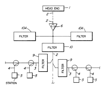
12 Turning now to ~igure 3, a network is
13 shown which is generally similar to that shown in
14 Figure 1, but has the addition of narrowband upstream
filters 9, connected in series with each of the
16 distribution lines 3 adjacent the point at which they
17 are connected to the trunk 2. The upstream filters 9
18 should be bandpass filters having narrow passbands
19 centered on the upstream signalling carrier
frequencies, e.g. in the preferred embodiment at 11
21 and 26 mHz, and having the bandwidth OL the upstream
22 signalling signals, i.e. 1 mHz wide.
23 In one embodiment the filters 9 are
24 passive, allowing the full high band downstream signal
to pass, but only allowing the narrowband upstream
26 signalling signals to pass upstream. Thus nearly all
27 of the upstream noise from each of the distribution
28 lines will be blocked; the only noise which will pass
29 upstream is the relatively small amount of noise
energy contained within the narrow passband of the
31 filters. Clearly this substantially reduces the
32 amount of noise gathered and applied to the trunk and
33 head end amplifiers, substantially improving the
34 signal to noise ratio in the trunk outside the narrow
band, and substantially reducing the possibility of
36 overloading the trunk bidirectional amplifiers which
37 would reduce the signal to noise ratio within the
38 - 10 -
,
, , :. ,.
~2~23~
01 narrow band(s) at the head end.
02 In a second embodiment the upstream
03 ~ilters 9 contain active circuits, to be described
04 below, which detect the energy con~ent o~ the signal
05 within the passbands of the upskream filters. In the
06 case of noise, almost all of the time the energy
07 content of those passbands will be low~ However if a
08 signal is being transmitted from the subscriber
09 station equipment, it will be concentrated within the
filter passband. The energy level in that case will
11 thus be much higher.
12 Each of the upstream filters contains a
13 gate which stops all signals from passing upstream
14 into the trunk. Thus the noise passed into the trunk
from the distribution lines will be reduced to a
16 negligible value When the energy which results from
17 the transmission of a signal from the subscriber
18 station equipment, which is concentrated within the
19 passband of the filters, is received, its energy level
will be high, and above a predetermined threshold.
21 When this threshold has been exceeded, the gate opens,
22 allowing those signals within the passband of the
23 filter to pass upstream. Since typically only one
24 subscriber will be transmitting at a time (although
this is not universally true), only one upstream
26 ~ilter will be open at a time and thus the signal and
27 the very small amount of noise energy within the
28 upstream signalling narrowband will be carried from
29 the single distribution line through trunk 2 to the
head end 1. The amount of total noise energy thus
31 received by the head end will be reduced to the
32 portion contributed by that distribution line, and
33 only the noise within the narrow signalling band
3~ Clearly also any excessive noise in one
subnetwork is kept isolated from aff~cting the other
36 subnetworks by the filters.
37 In accordance with a third embodiment, the
38 - 11
.:
~:;:
: . , :- ~: : : .
., . ~
- ~2723`~
01 upstream filters 9 are passive, as described with
02 respect to the first embodiment, but active filters 10
03 and lOA are connected in upstream series with the
04 trunk 2 to isolate and divide the network.
05 Subnetworks are subdivided by series ac-tive ~ilters
06 lOAo Active filters 10 and lOA are similar to filter
07 9 as described with reference to the second
08 embodiment, that is, each contains a gate which stops
09 the transmission of all upstream signals in the
associated subnetwork until an upstream signal
11 exceeding a predetermined threshold within the
12 narrowband upstream signalling bands is received, then
13 it will open, allowing the signalling signals to pass
14 upstream.
It should be noted that active -filters 9
16 and 10 and lOA in whatever form are used, are
17 transparent in the downstream direction, allowing the
18 high frequency band signals to pass downstream,
19 unimpeded.
If filters 10 and lOA are present, they
21 are active, and filters 9 may be active or passive ~as
22 described above). If filters 10 and lOA are not
23 present, filters 9 can be either active (as in the
24 second embodiment) or passive (as in the first
embodiment).
26 In accordance with a fourth embodiment,
27 active filters 10 and lOA may or may not be present,
28 but at least upstream filters 9 are individually
29 addressable from head end 1. When addressed to either
be purposely opened or closed, they allow the head end
31 to test or control the transmission of signals passing
32 along one or more distribution linesO
33 In accord~nce with another embodiment, a
34 separate conditioned line for carrying upstream video
is connected to the upstrea~ filter, and the upstream
36 filter bandwidth is wider, sufficient to accommodate a
37 video signal. The filter senses the video signal
38 - 12 -
, , . , . ~ ~ , .
01 presence as exceeding a threshold, and opens. While
02 the video camera can be locally or remotely
03 controlled, the filters are controlled by sensing of
04 the video (or indeed any other upstream signal such as
05 a conferencing signal) from the cameras. Indeed the
06 video filter can be in the same narrow band upstream
07 signalling filter described above. This allows
08 subscriber station equipment connected to the trunk
09 through reconditioned or individual drops on the
distribution line to generate video signals, which can
11 be switched into the trunk and head end by the
12 automatic sensing of the signal pressure or by the
13 head end addressing the upstream filters 9. It may be
14 desirable in this or in other embodiments to locate
the upstream filters adjacent or at the subscriber
16 station equipment or to make the station equipment
17 remotely controlled from the head end.
1~ By arranging several subscriber stations
19 together in one room, with video cameras connected as
the subscriber station equipment, and by the use of
21 the upstream filters described above, remote studios
22 can be formed, remotely controlled from the head end 1
23 by using the upstream filters as remote switchers or
24 by automatic sensing of the video signals, switching
remote selectable video signals generated at the
26 subscriber station video equipment into the trunk and
27 into the head end as desired at the head end. The
28 CATV network is facilitated for this upstream
29 transmission also because of the reduction of noise
gathering due to use of the filters in the remaining
31 subnetworks or distribution lines of the s~ste~.
32 Figure 4 is a block diagram of a preferred
33 form of an active filter for use in the present
34 invention. The lead 3A represents the input o~ the
upstream part of a cable distribution line and the
36 lead 3B represents the input of the downstream part of
37 the cable distribution line. A high band bandpass
3~3 13 -
, :, . .
.. ::~ . . ~ , .
~ 32723:`~
01 filter 13, e.g. for passing signals between 50 and 400
02 mHz is connected in the trunk or distribution line
03 between leads 3A and 3B, to allow high band signals to
04 pass downstream, but to block low band upstream
05 signals. The arrows represent the signal direction.
06 60 Hz power is typically passed from
07 either direction along the cable to power remote line
08 amplifiers. A 60 Hz low pass filter 14 is connected
03 in parallel with filter 13. This allows 60 Hz power
signals to pass around filter 13 along the
11 distribution line or the trunk from lead 3A to lead 3B
12 or vice versa.
13 Part of the 60 Hz signal is tapped, and is
14 applied to AC/DC converter 15, which generates e.g. 12
volts DC for operation of the active -Eilter to be
16 described below.
17 Also connected in parallel with filter 13
18 is an upstream low band bandpass filter 16. This
19 filter is powered from the 12 volts DC generated in
converter 15. Filter 16 passes the upstream
21 signalling signals from lead 3B to lead 3A along the
22 distribution line. It also blocks all upstream
23 signals outside its pass bands. In the preferred
24 embodiment the filter 16 has one mHz passband centered
at 11 and 26 m~z, as shown in Figure 2B.
26 With the use of the embodiment of Figure
27 4, it may be seen that upstream noise within the low
28 frequency upstream band 5-30 mHz is blocked from
29 passing upstream through filter 13 because it has a
passband only between 50 and 500 mHz. Similarly
31 filter 14, being a 60 Hz filter, will not pass
32 upstream signals between 5 and 30 mHæ. The upstream
33 bandpass filter 16 blocks all signals except for those
34 within the upstream signalling bands, which can be one
or more narrowbands, but which preferably is at the 11
36 and 26 mHz center frequencies as described above.
37 Thus virtually all noise is blocked from being passed
38 - 14 -
01 upstream.
02 The downstream high band bandpass filter
03 is a conventional LC filter and need not be described
04 in detail as it is known to those persons skilled in
OS the art.
06 Also in the preferred embodiment, upstream
07 bandpass filter 16 contains a gate which blocks noise
08 even within the upstream signalling bands, unless the
09 energy level is above a predetermined threshold. A
10 detailed descxiption of this active filter will be
11 given below.
12 Referring to Figures 6 and 7 placed
13 together as shown in Figure 5, the upstream signal is
14 received on lead 3B and is amplitude limited by
15 inversely poled parallel connected diodes 20A and 20B
16 connected between lead 3B and ground. The signal is
17 then passed into a preamplifier 21, where it is
18 amplified, through a multiple segment L-C filter 22,
19 having a 26 mHz or 11 mHz center frequency and 1 mHz
20 passband, and passes through an output amplifier 23
21 from which it is capacitively coupled by capacitor 24
22 to a signal splitter 25. The circuit so far described
23 provides an output signal at 11 or 26 mHz, one mHz
24 broad.
The output signal is amplified further in
26 amplifier 26, from which it is applied to the input of
27 an electronic switch 27. The electronic switch 27
28 must switch very quickly, e.g. within a microsecond.
~9 A switch which has be~n found very satisfactory for
30 this is type 4053B.
31 The output of electronic switch 27 is
32 capacitively coupled by capacitor 28 to a 75 ohm pad
33 29 to the distribution line 3A, which typically will
34 be operating at an impedance of 75 ohms.
Thus, when electronic switch 27 is
36 enabled, the input signal from lead 3B, restricted to
37 the passband of the filter e.g. at 11 or 26 mHz center
38 - 15 -
: : : . :,.: :,:
:. ::: : : : :
. .
.
.
~3~7~
01 frequency and 1 mHz wide, will be switched with great
02 speed to distribution line lead 3A, from which it
03 passes upstream to the trunk.
04 In order to control the operation o~ the
05 electronic switch 27, the signal Erom splitter 25 is
06 applied via capacitor 30 bypassed by resistors 31 and
07 32 at both ends thereof, to a half wave rectifier
08 diode 23, the output signal of which is integrated by
09 capacitor 34 bypassed by discharge resistor 35. This
accumulates the energy in the input signal and
11 provides a variable DC output voltage which is
12 proportional thereto. The resulting variable DC
13 output voltage is amplified in operational amplifier
14 36, the output signal of which is applied to the
noninverting input of operational amplifier 38.
16 A circuit identical to that described
17 above connected between elements 30 and 36 is
18 connected to the inverting input of operational
19 amplifier 38, the elements of which having been
similarly labelled followed by the designation A, that
21 is, elements 30A - 36A. The purpose of elements 30A -
22 36A is to provide reference level compensation for the
23 rectifying circuit in the previously described branch
24 connected to the noninverting input of operational
amplifier 38. This provides both temperature
26 compensation and level compensation for the diode
27 threshold and for the element variances caused by
28 temperature variation. Resistors 37 and 37A
29 respectively connect the outputs of amplifiers 36 and
36~ to the noninverting and inverting inputs of
31 amplifier 38. Resistor 37C connects the noninverting
32 input to -lOV and resistor 37B connects the inverting
33 input of amplifier 38 to its output.
34 The integrating circuit described above
i 35 determines the speed of detection and should have a
36 time constant of 5 microseconds or less. It should be
37 short enough to open, so as not to cut off a signal
38 - 16 -
:; : i
: . - . i,
.
~;2~23~
01 but long enough to avoid triggering by noise. In case
02 the input signal is video (requiring the filter
03 comprised of elements 21, 22 and 23 to be
04 substantially broader in bandwidth than described
05 earlier to accommodate the video), the switching speed
06 of the integrator can be substantially relaxed. It
07 should be noted that the lon~er the ti~e constant, the
08 greater the reliability will be.
09 The output signal of amplifier 38 is
connected to a level detector. This is prefexably
11 comprised of an operational amplifier 39, to the
12 inverting input of which the output signal of
13 amplifier 38 is applied. The detection threshold is
14 set by the noninverting input to amplifier 39 being
connected through resistor 40 to the tap terminal of a
16 potentiometer 41, which itself is connected in series
17 with resistors 42 and 43 at its opposite terminals
18 respectively between a source of -20 V and ground.
19 The tap terminal of potentiometer 41 is by-passed to
ground by capacitor 44.
21 The threshold setting circuit will cause
22 amplifier 39 to output either 0 volts or -20 volts
23 when the rectified and integrated input signal from
24 splitter 25 is above or below the level set on
potentiometer 41 between -20 V and ground (0 V). This
26 output signal is applied to the cathode of diode 45
27 through resistor 46. The anode is connected to -17.2
28 V. Thus when the output of amplifier 39 is 0 V diode
29 45 will be reverse biased (off), and when the output
of amplifier 39 is -20 V, diode 45 will be biased into
31 its conducting state and the Yoltage on its cathode
32 wiIl be approximately -17 V. With the cathode of
33 diode 45 connected to the control input 48 of
34 electronic switch 27 the electronic switch will be
turned on when diode 45 is conducting, i.e. when the
36 output of amplifier 39 is -20 V, and off when diode 45
37 is reverse biased.
38 ~ 17 -
: .
- : . . : -
';
.' '''. ` , 7 .
132723~
01 With the time constant of the integrator
02 less th~n 5 microseconds, and the switching ti~e of
03 electronic switch 27 less than 1 microsecond, clearly
04 when the input signal results in the threshold set by
05 potentiometer 41 is exceeded, electronic switch 27
06 will cause the input signal passing through the filter
07 and appearing at splitter 25 to be switched very
08 rapidly to t2le upstrea~ distribution line lead 3A.
09 The switch sta-te monitor lead could also
be connected to a control input of filter 22 (if it
11 were made on active filter), to control and thereby
12 open or close its bandwidth.
13 The above-described circuit should be
14 duplicated for each of the narrowband signalling
signal frequencies appearing on the same distribution
16 line or trunk. In the case of two signals transmitted
17 at different sequential times at the 11 and 26 ~H~
18 signalling bands e.g. using MSK, only one or the other
19 of the filters will be transmitting at a time. This
can further reduce the amount of noise carried
21 upstream of the filter into the trunk over the case in
22 which both signals are transmitted simultaneously
23 ~mf).
24 Additional enhancements may be made to the
above-described circuit. For example the contxol
26 input to electronic switch 27 can also be connected to
27 the output of an addressable receiver-controller 47,
28 which responds to an uni~ue code received in the
29 downstream direction from the head end in the hiyh
frequency band. This will be described in more detail
31 with respect to Figure 8. However with respect to the
32 present figure, controller 47 receives a signal,
33 demodulates it, decodes it and applies a constant open
34 or constant close level enable signal ~0 or -17 V) to
the control input of electronic switch 27. This can
36 forcibly control the transmission of signals upstrea~
37 through electronic switch 27 for testing or for
38 - 18 -
. . -~ ~ , . . .
:: - :
: ~ : `::
.
132723~
01 signalling source control purposes, as described
02 earlier.
03 A second contact 27A in electronic switch
04 27 can be conn0cted through capacitor 48A to a switch
05 state monitor lead. This switch state monitor lead
06 can provide signals input to it e.g. to the upstream
07 lead 3A, or to another swi~ch to provide
08 acknowledgement of the receipt of the remotely
09 controlled electronic switch control command which is
received by controller 47, or to provide a second
11 switch state indicative to the head end and or to
12 local control equipment.
13 The switch sta*e monitor lead can be
14 connected to the input of an encoder 49, the ou~put of
which is connected to a modulator 50, which has its
16 output connected through a 75 ohm line matching pad
17 29A, to upstream lead 3A. In this case the receipt oE
18 an addressable command causes switch 27 to operate.
19 As a result a pulse appears at the input of encoder
49, which generates a code, modulated in modulator 50,
21 which is applied through output pad 29A to the
22 upstream lead 3A. This can be used to provide
23 acknowledgement of the receipt of a command to close
24 switch 27, since in the case of testing of switch 27,
there may otherwise not be any input signal passing
26 therethrough to be received and noted by the head end.
27 Alternatively the output of modulator 50
28 can be connected into the input of switch 27 for
29 transmission of an acknowledgement code generated by
encoder 49 through switch 27 as if it were a signal
31 received through the filter comprised of elements 21,
32 22 and 23.
33 A block diagram illustrating a variation
34 of the above is shown in Figure 8. In this figure
high pass filter 13 is connected between leads 3A and
36 3B as described with reference to Figure 4. The
37 upstream signal is passed through a low band bandpass
38 - 19 -
~: -,
~327238
01 filter 52 which passes signals between e.g. 5 - 30
02 mHz. The upstream signal then passes through an
03 amplifier 53 and a narrowband upstream signal filter
04 54 such as that described with respect to elements 21,
OS 22 and 23. The output of filter 54 is connected to
06 the input of electronic switch 55, which is controlled
07 by a threshold detector/control circuit 56 such as
OB that described earlier with respect to elements 30 -
09 45 in Figures 5, 6 and 7. The output of switch 55 is
connected to the input of another filter 57 which is
ll similar to filter 54. The output of filter 57 is
12 connected to the upstream lead 3A, which is the
13 distribution line connected to the trunk.
14 A downstream control signal within the
high band is received on lead 3A, passes through
16 control signal frequency filter 57A and is received in
17 demodulator 58. The demodulated signal is decoded in
18 decoder 59, and the decoded control signal is applied
l9 to the control input of switch 55, in a manner similar
to that described with reference to contxoller 47
21 controlling switch 27.
22 The switch state monitor output of switch
23 55 similar to that described with respect to switch 27
24 is connected to one of several input terminals of an
encoder 60 which has its output connected to modulator
26 61, which has its output, in the low frequency band,
27 connected to the input of filter 57, from where the
28 output signal of modulator 61 is applied to upstream
29 3A for application to the trunk and to the head end.
It should be noted that several decoders
31 similar to decoder 59 can be connected to the output
32 of demodulator 58, each one of which can be connected
33 to a separate input of encoder 60 through controlling
34 of another switch simiIar to switch 55. This can
clearly be used to apply various input signals to the
36 upstream distribution line and trunk. For example,
37 such signals can be from power meters, video signals,
38 - 20 -
:: .
:. - ~ . : : , . : ~.
~32~,~38
01 acknowledgement of appliance ~urn on at subscriber
02 locations, etc. Further, decoded signals from the
03 head end can be used to switch appliances on and off,
04 activate power circuits, etc. at the subscriber
05 location. Indeed, control signals from subscriber
06 stations can be sent upstream to the head end to
07 command certain ~unctions, such as the transmission of
08 control signals to control or monitor units a~ the
0~ same or different subscriber stations.
The above description oE embodiments of
11 the invention have clearly shown that the present
12 invention can be used for a variety of various
13 functions, but at its heart provides means for
14 providing signals to a head end with reliability and
substantially reduced of noise. Figure 9A illustrates
16 , the spectruln of the signal received at a head end with
17 a prior art network and is comprised virtually
18 entirely of noise; Figure 9B illustrates the spectrum
19 ~f the signal received at the head end utilizing the
present filters and is clearly almost clear of
21 significant noise; and Figure 9C illustrates the
22 spectrum of signal received at the head end with a 26
23 mHz upstream signalling signal used in accordance with
24 the present invention, and clearly illustrates a very
high signal to noise ratio. The improvement over the
26 prior art is seen to be substantial.
27 A person understanding this invention may
28 now conceive of other alternatives or embodiments
29 using the principles described herein. All are
considered to ~e ~ithin the sphere and scope of the
31 invention as defined in the claims appended hereto.
32 - 21 -
, : . i
' ',, ~";'' '':'
.. . . .