Note: Descriptions are shown in the official language in which they were submitted.
13275~3
~ISPENSER ÇLOSURE
BACKGROUND OF THE INVENTION
The present invention relates to closures for
containers for spices or other condiments ~ormally
provided in particulate or granular ~orm, and more
particularly is related to a closure for a ondiment
container adapt~d for either sifting, pouring or
spooning.
Friable particulate matter such as spices and
other condiments normally is packaged in metal tins or
glass or plastic jars. The closures o~ conventional tin-
type containers have formations adapted for sifting,pouring and/or spooning. V.S. Patent No. 1,959,B74
discloses a tin~yp~ condiment container including a
closure having a cover plate and a slide plate adapted to
slide over the cover plate. The cover plate is proYided
with a plurality of ~ifter openings at one end and a
retractable spout for pouring at the other end. The
slide plate is provided with a like plurality of sifter
openings whi~h may be placed in registry with the cover
plate sifter openings and also has a spout opening which,
depending on its position, may partially block the
pivoting action of the metal spout to pravent the spout
.. *
~. :
~32~3
from extending for pouring. Thus, when it is desired to
sift condiments from the cont iner, the slide ~late is
manipulated so that the si~ter openings o~ both the slidP
plate and the cover plate are in regis~ry with each
other. In this position, the spout is prevented from
opening. In situations wher~ pouring is desired, the
slide plate is slid across the cover plate so that the
rekractable spout may be opened, and at the same time the
sifter openings in the cover plate and slid~ plate are
out of registry, thus preventing the escape of condiments
from those openings wh;le pouring. A major drawback of
this design i5 the lack o~ any capability for spooning.
In the case of metal tin-type condiment
container~ currently ~vailable, it is conventional to
provide an integral plastic closure having three separate
openings, each with its own hinged snap-fit lid, one for
sifting, one for pouring and one large enough to insert a
measuring spoon kherein. The user selects the most
appropriate type of condiment distribution method and
then opens the appropriate lid to distribute the
condiment accordingly. The lids are designed so as to
not disgor~e condiments unless they are opened.
In t~e case of glass or plastic jars normally
used as containers for spices, it is common to provide a
detachable sifting fitment adapted to be snap-fit upon
the open mo~th o~ the jar. The jar is then capped by a
plastic closure which is helically threaded to be
attached to the jar's mouth. When pouring or spooning is
desired, the fitment may be removed. The disadvantages
~3275~3
of such conventional ~ar closures is khat the sif~ing
fitment may be easily lost, and that it is inconvenient
to readily convert the container from pouring to sifting.
A further disad~antage of prior art closures is that the
pouring spouk or spoon opening is not large enough to
accommodate a wide range of siz~s of measuring spoons.
Thus, there is a need for an economically produced
closure ~or a glass or plastic jar-type rondiment
container which provides the capability of readily
converting from sifting to pouring and/or spooning and
vice versa.
Accordingly, the present invention provides a
closure for a jar-typP container capable of being readily
converted for either sifting or pouring and/or spooning.
SUMMARY OF THE INVENTION
A dispenser closure for a container includes a
body having a generally planar top portion with a
peripheral edge margin and an annular sXirt por~ion
depending therefrom, at least one sifker or pourin~
opening, a larger opening for spooning or pouring and a
pair o~ diametrically opposed, vertically projecting
slide guides; as well as a substantially planar solid
slide plat~ being dimensioned to slidingly engage the
slide guides to cover the top portion and being capable
of selectively exposing either the sifter opening or the
spoon opening. The closure of the invention may be
further provided with a stop formation adapted to limit
the degree of travel of the slide plate across the top
. . , :,. , ,, ,:,,, -
132 1~43
portion of the body. The closure may be used to dispense
~pices, o~her condiments of a particulate nature, as well
as all friable particulate matter.
BRIEF DESCRXPTION OF TH:E: DRAWINGS
FIG. 1 is a plan view of the sifter closure of
t:he invention showiny the sli~e plate detached from the
body;
FIG. 2 is a bottom view of the slide plate as
shown in FIG. l;
FIG. 3 is an exploded front elevation of the
closure of FIG. 1 with a portion of the body cut away;
FIG. 4 is a plan ~iew o~ the closure of the
invention shown in the spooning or pouring position; and
FIG. 5 is a plan view o~ the closure of the
invention shown in the sifting position.
DESCRIPTION OF THE PREFERRED EMBODIMENT
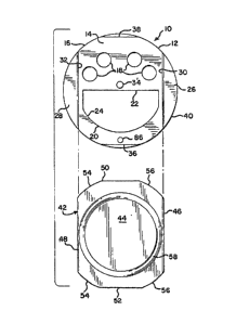
Referring to FIG. :L, the dispenser closure o*
the invention i~; indicated, and is c3esignated generally
by the r~ference numeral 10. The closure 10 includes a
body 12 having a generally pl~nar top portion 14 with a
peripheral margin 16. ThP top portion 14 further
includes at least one sifter opening ~8. In the
preferred embodiment, four generally circular s~fter
openings 18 ~re proYidedr The top portion 14 als~
include~ a substantially l~rger 'D'-shaped spoon or
pouring opening 20 having a substantially linear edge
margin 22 and a substantially 'C'-shaped edge margin 24.
,
~. ~ ... :. . ,;
~ 3 ~ 3
Other shap~s may be used for the openings 18 and 20 as
may be found desirable. A pair of vertically projecting
slide guides 26 and 28 are positioned near th periphery
16 of the top portion 14 and are located in generally
diametrically opposed relationship to each other. Each
vertically projecting slide guide 26, 28 is provided with
a vertical face 30 and 32, respectively. A vertically
projecting, substantially cylindrical boss 34 may be
centrally located upon the top portion 14. A pair of
thumb slots or ~lat spots 36 and 38 may optionally be
located diametrically opposite each other on the
periphery 1~ of the body 12 and are located ~pproximately
90 degrees from the Yertically projecting slide guides
26, 28. The ~lat spots 36, 38 are located in an annular
skirt 40 (best ~een in FIG. 33 which depends from the
outer periphery 16 of the body 12.
A slide plate 42 includes a solid body 44
having first and second side edges 46 and 48 which are in
generally parallel relationshi.p to sach other, and first
and second ends 50 and 52~ respecti~ly, each of which is
provided with generally rounded edge margin portion~ 54
and 56, respectively. It will be seen that the slide
plate 42 is dimensioned to cover the top or face portion
14 between the slide guides 26 and 28, the latter
designed to be slidingly engaged by the side edyes 46 and
48. Althoug~ t~e slide plate 42 is shown being inserted
at th~ end of the body 12 nearest the spoon opening 20,
the plate 42 may also be inserted at the end of the body
12 nearest the sifter openings 18. Thus, either end 50,
: ~ , . ' ' ' . ,
1 3 ~ 3
52 of the plate 42 may be inserted in either end of the
top portion 14. Alternatively, the plate 42 may bP snap-
fit onto the top portion 14 from abov2. A vertically
projecting annular rib 58 sr other decoration may
optionally be attached or integrally formed upon the top
of the body 44. The body 12 and the slide plate 42 are
pref~rably fabricated of a plastic material such as high
density polyethylene, low density polyethylene,
polypropylene or polyctyrene, however, the use of other
suitably rigid materials is contemplated.
For greater ease o~ sliding motion between the
slide plate 42 and th~ body 12, each such eomponent may
be fabricated of a dissimilar material having specific
characteristics, i.e., th~ ~lide plata 42 may be
fabricated of material having a different coefficient of
friction relative to the body 12 to facilitate the
sliding motion or restrict such motion as desired. In
one embodime~t, it is contemplated that the closur~ 10
may have a polypropylene body 12 adapted to be used with
a polye~hylene slide plate 42. As a further alternative,
the slide plate 42 may be fabricated of a transparent or
translucent material which enables the user to accurately
select the desired opening i8 or 20 which is best suited
to the user~s particular need. In some cases, it may be
desirable to provide the body 12 and the slide plate 42
in dissimilar colors for ease of differentiating the
contents of idPntically shaped containers.
Referring now to FIG. 2, the underside Ç0 of
the slide plate 42 may be provided with an elongate
: ~ ,
~2~3
groove 62 which is centrally located on the body 44 and
is dimensioned to slidingly accommodate the boss 34
therein. ~he us~ o~ multiple grooves 62 and
corresponding bosses 34 ~s al~o contemplated. The slot
62 is provided with a pair o~ truncated ends 64 and 66,
each of which is rounded to correspond with the
cylindrical shape of the boss 34O It will be evident
that the ends 64, S6 of the ~lot 62 do not reach the
front and rear ends 50, 52 of the slide plate 42. In an
alternativ~ embodiment ~not sh~wn~, a boss may be
provided on the undersid~ vf the plate 42, and may be
adapted to engage a groove in the upper surface 14 of the
body 12. In a further alternative embodiment, the slot
62 may include a linear series of detentes (not shown~,
which engage the boss 34 and thus permit the slide plate
42 to be fixedly placed in a d~sired partially or fully
open position.
A locXing boss 86 (best seen in FIG. 1) may
also be provided on the closure 10, such as on either end
20 of the top surface 14 near the re~pec~iv~ flat spots 36,
38, and in linear arrangement with the boss 34 where it
can engage the slot 62 to prevent inadvertent opening of
the closure 10. In the preferred embodiment, the locking
boss 86 is relatively smaller in overall dimensio~ than
the boss 34 to permit the plate 42 to be slid thereover.
If, as an alternati~e embodiment, the groove 62 is
located in the body 12 and the boss 34 is provided on the
underside 60 of the plate 42, the locking boss 86 may
also be pro~ided on the underside 60.
.
. . .
'
', ~ '
~327~3
Referring now to FIG. 3, the slide plate 42 is
provided with a linear rib or bead 68, 70 located alony
~ach side edge 46, 48 thereof. Correspondingly, the
verti~al ~aces 30, 32 of the ~lide guide~ 26, 28 are al~o
each provided with a recess or groove 72, 74 d~signed t9
matingly engaqe the respective ribs 68, 70 and to provide
a releasable enap-fit betwee~ the slide plate 42 and the
slide guides 26, 28. I~ desired, the slide plate 42 may
be captured in its sliding movement within the slide
guides. In one embodiment, an interior surface 76 of he
skirt 40 is provided with an integral helical thread
formation 78. The thread formation 78 is designed to
threadably engage the threaded outer upper rim of a
suitable container such as a glass vr plastic spice jar
(not shown). A lower rim 80 of the skirt 40 defines an
open lower end of the closure 10 which is adapted to
allow the threaded end o~ the jar (not shown) to be
inserted in~o the interior of the closure lo for
engagement with the thread formation 78. ~he closure 10
may also be a snap-fit closure, as known in the art.
Referring now to FIG. 4, in operation, the
closure 10 is assembled by placing the slide plate 42 in
releasably locked sliding engagement between the
vertically projecting slide guides 26 and 28. In FIG. 4,
the ~losure 10 is shown in the pouring or spooning
position. In this position, the slide plate 42 has been
moved laterally in the direction indicated by the arrow
82 from a closed position to reveal the sponn opening 20.
The content~ of he jar sr container may now be removed,
.
1 3 ~ 3
either by pouring or by inserting a measuring ~poon (not
shown) into the opening 20. The opening 20 is large
enough to accommodate a ~ariety of measuring spoons
therein, and the ~ inear margin 22 of the opening 20 is
con~igured to pe~mit a l~veling oPf of the spooned
contents to facilitate accurate measuring.
When sufficient spices ~r other condlments have
been extracted from the container and out through the
closure 10, the slide plate 42 may be moved ~y the user
in the direction indicated by the arrow 84 to cover all
openings 18 and 20 of the top portion 14 of ths closure
10. It will be evident that when the ~lide plate 42 i8
moved to the position indicated in FIG. 4, that the
sifter openings 18 are completely covered, preventing the
escape of any condiments there!from.
The extent of linear movement of the slide
plate 42 in the direction indicated by the arrow 82 is
limited by the interaction of the rounded edge 66 against
the boss 34 which acts as a stop. With the rounded end
~0 66 engaging the boss 3~, the slide plate 42 may be
maintained in a position to allow full accessability to
the spoon opening 20 while covering all of the sifter
openings 18. Thus, the condiment or other contained
product may be spooned out of the container or poured as
desired~
The flat spots or thumb slot~ 36, 38 are
designed to enable the user to secure a good grip upon
the closur~ 10 and to obtain adequate leverage to
manipulate the slide plate 42 in reciprocating fashion in
g
, . . , ,:
.
. .. .
'~
~27~43
either of the directions indicated by the arrows 82 and
84.
Referring now to FIG. 5, the closure 10 is
shown in the sifting positiQn wherei~ the slide plate 4~
has been ~oved in the direction indicated ~y the arrow 84
to uncover the sifter openings 18. In similar fashion to
the operation as disclosed above in FIG. 4, the extent of
linear movement of the slide plate 42 in the direction
indicated by the arrow 84 is limited by the interaction
between the round~d end 64 o~ the slide plate 42 an~ the
boss 34. Thus, in the sifting position as depi¢ted in
FIG. 5, all of the sifter openings 18 are uncovered,
while the spoon opening 20 is totally covered, preventing
the escape o~ any condiments or other particulate matter
therefrom~ When a su~ficient amount of condiments or
other particulate matter has been removed by sifting, the
slide plate 42 may be manipulated in the direction 82 and
returned to its original pusition to cover all openings,
both the sifter openings 18 and the spoon or pouring
opening 20.
Thus, the closure 10 of the invention discloses
a closure apparatus designed to be used for condiment
jar~ w~ich provides the capability of either sifting,
sp~oning or pouring by a simple movement of a slide plate
42. Although in the preferred embodiment, the slide
plate 42 may be removed i~ desired, in operation the
reciprocal movement thereof is designed to selectively
provide exclusive access to either the sifter openings 18
~27~43
or the spoon opening 20. The closure ~nd slide plate may
also be configured to prevent removal of the slide plate.
While a particular embodiment of the dispenser
closure of the inv4ntion has been shown and described, it
will be appreciated by persons ~killed in the art that
variation& and modifications might bs made without
departing from the invention in its broader aspects and
as set forth in the following claims.
11
;
.. , , : . ~ , , , :
~, : ~. ,; :: ,,