Note: Descriptions are shown in the official language in which they were submitted.
13279~0
--1--
CATHETER FO~ BALLOON ANGIOPLaSTY
BACKGROUND OF THE INVENTION
Field of the Invention
This invention relates generally to surgical
procedures employing a flexible catheter guide and more
particularly to an apparatus for use in balloon
angioplasty.
Prior Art
Catheters require the capability of being pushed
and flexibility in order to be effectively inserted
into blood vessels and maneuvered through a vascular
tree. Often a hollow spring wire shaft is used as a
catheter, such catheter including a movable core wire.
A balloon may be used in conjunction with
various catheter constructions such that the balloon
may be inflated within the vessel, thereby opening
blockages found therein. However, the combination of a
hollow spring wire shaft and a movable core wire of
variable properties has not been used in conjunction
with a balloon.
U.S. Patent No. 4,276,874 discusses a balloon
catheter including an elongated coil spring defining an
inner passage, the spring being covered by silicone in
the form of an extendable sheath, strain collar, and a
balloon tip affixed to the ætrain relief collar. A
portion of the elongated coil spring and sheath form a
support structure which perceptibly elongates when
excessive stretching force is applied to the support
structure when moving the balloon through a body
... . ............ . . . . . . ..
. ~ ' .,: '
. .
. .. . .
- 1327930
--2--
passage. Unfortunately, such a catheter is unsteerable
and does not have variable flexibility.
Another device, disclosed in U.S. Patent No .
4,723,936, is a coil spring guide including a deflect-
able tip which comprises a coil spring covered by asheath, a core wire within the coil spring extending
the length of the coil spring, and a head member. At
the proximal end of the coil spring guide a mechanism
is provided to enable movement of the coil spring
relative to the core wire. The core wire is eccen-
trically fixed to the back side of the head member and
adjacent a lateral side thereof, thereby causing
compression of the distal end spring coils and deflec-
tion thereof in a direction laterally from the side of
the head member to which the core extension is fixed
upon rearward movement of the core wire. Such a
standard low profile catheter with a fixed wire system
additionally does not offer a combined over-the-wire
system nor variable column strength.
Still another device, disclosed in U.S. Patent
No. 4,548,206, is directed to a catheter wire guide
with a movable mandrel having a tapered tip which
permits the flexibility of the distal tip of the wire
guide to be varied. This device provides for a
helically wound wire having an opening therethrough and
a mandrel positioned within the opening and longitudi-
nally movable therein relative to the helically wound
wire for varying the flexibility of the distal tip of
the wire guide. The device is a diagnostic or wire
placement device and not a balloon catheter suitable
for angioplasty.
Although the foregoing devices include some
advantageous features, they are limited in that they do
,. :
~32793~
--3--
not combine the following desirable features: a
movable core means; variable stiffness of the shaft
secondary to the movable core means and therefore
variable trackability and pushability; a deflection
mechanism for deflecting the tip of the catheter while
still allowing torque and rotation; an ultra low
profile, such that the device may be used in conjunc-
tion with a standard diagnostic coronary catheter
rather than a guide catheter, referred to as a PTCA
guiding catheter; the capability to transform from a
fixed wire system to an over~the-wire system by removal
of the movable core means; and the ability to insert
either fiber optic angioscopes or laser fibers through
the hollow portion of the catheter.
The foregoing illustrates limitations known to
exist in present devices. Thus, it is apparent that it
would be advantageous to provide an alternative device
directed to overcoming one or more of the limitations
set forth above. Accordingly, a suitable alternative
is herein provided including features more fully
disclosed hereinafter.
SUMMARY OF THE INVENTION
One aspect of the present invention provides a
catheter for balloon angioplasty comprising:
a flexible shaft having a hollow passage
therein, said flexible shaft having a first proximal
end which is open and a second distal end which is
closed;
a core means movably and removably mounted
within said passage, said core means having a first
proximal end and a second distal end, said ends
ad~acent said first and second ends of said flexible
shaft, respectively, said core means having a first
,
~327~3 0
flexible portion extending along its length from said
first proximal end and a second flexible portion being
of greater flexibility than said first flexible
portion, said second flexible portion extending to said
second distal end, said core means having an enlarged
terminal knob at said second distal end thereof, said
knob contacting said second distal end of said flexible
shaft upon axial movement of said core means, further
axial movement of said core means causing bending and
buckling of said second flexible portion of said core
means in turn bending said flexible shaft and causing
angulation of said second distal end of said flexible
shaft;
a flexible guide wire externally attached to the
second distal end of said flexible shaft, said flexible
guide wire axially extending away from said second
distal end; and
an inflatable member having a non-inflatable
sheath covering an external surface of said flexible
shaft near the second distal end of said flexible shaft
and further including means for inflating said inflat-
able member.
Another aspect of the instant invention provides
a catheter for balloon angioplasty comprising:
a flexible shaft having a hollow passage
therein, said flexible shaft having a first proximal
end which is open and a second distal end which is
partially open having a reduced cross-section;
a core means movably and removably mounted
within said passage, said core means having a first
proximal end and a second distal end, said ends
adjacent said first and second ends of said flexible
shaft, respectively, said core means having a first
flexible portion extending along its length from said
first proximal end and a second flexible portion being
.. . . . .
., .. . ~ , . .
, '. '
1327930
-5-
of greater flexibility than said first flexible
portion, said second flexible portion extending to said
second proximal end, said core means having an enlarged
terminal knob at said second distal end thereof, said
knob contacting said reduced cross-section of said
second distal end of said flexible shaft upon axial
movement of said core means, further axial movement of
said core means causing bending and buckling of said
second flexible portion of said core means bending said
flexible shaft and causing angulation of said second
distal end of said flexible shaft; and
a flexible guide wire attached to said terminal
knob and axially extending away from said knob, said
guide wire axially extensible through the opening in
said second distal end of said flexible shaft.
Yet another aspect of the instant invention
provides a catheter for balloon angioplasty comprising:
a flexible shaft having a sealed hollow passage
defined therein and having a first proximal end and a0 second distal end, both said ends being open;
a core means movably, removably and substantial-
ly contained within said flexible shaft, said core
means having a first proximate end and a second distal
end and having a first flexible portion extending from
said first proximate end and a second flexible portion
terminating in said second distal end of said core
means, said second flexible portion being of greater
flexibility than said first flexible portion, said
second flexible portion having a variable core strength
along the length thereof from greater to lesser
strength extending toward the second distal end of said
core means to provide trackability, pushability and
flexibility of said catheter;
::
- 132793~
--6--
a flexible guide wire fixed to and further
axially extending from the second distal end of said
core means; and
an inflatable member having a non-inflatable
sheath covering an external surface of said flexible
shaft near the second distal end of said flexible shaft
and further including means for inflating said inflat-
able member.
Further aspects of the invention reside in the
methods of using the catheters of the present invention
and in providing a kit containing the catheters and
other components sized to be used in conjunction with
said catheters.
The foregoing and other aspects will become
apparent from the following detailed description of the
invention when considered in conjunction with the
accompanying drawing. It is to be expressly under-
stood, however, that the drawing is not intended as a
definition of the invention but is for the purpose of
illustration only.
BRIEF DESCRIPTION OF THE DRAWING
Fig. 1 is a cross-sectional view illustrating a
portion of a first embodiment of the catheter of the
invention;
Fig. 2 is a second cross-sectional view illus-
trating the entire first embodiment of Fig. 1 of the
invention;
Fig. 3 is a third cross-sectional view illus-
trating the first embodiment of Fig. 1 of the invention
without an inflatable member and showing the core means
withdrawn from the shaft;
1327930
--7--
Fig. 4 is a cross-sectional view illustrating a
second embodiment of the invention;
Fig. 5 is a cross-sectional view illustrating a
third embodiment of the invention including a power
source;
Fig. 6 is a cross-sectional view illustrating a
fourth embodiment of the invention;
Fig. 7 is a cross-sectional view of a fifth
embodiment of the invention; and
Fig. 8 is a schematic view of a flow diagram of
methods of using the present invention. -
DETAILED DESCRIPTION
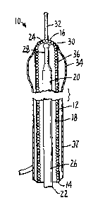
A catheter for balloon angioplasty, generally
designated 10, and illustrated in Fig. 1, includes a
flexible shaft 12 preferably formed of a suitable metal
such as Type 304 Stainless Steel and having an outside
diameter of from about 0.014 to about 0.035 inch (0.35
mm to about 0.88 mm). Shaft 12 has an open first or
proximal end 14, a closed second or distal end 16, and
defines a hollow passage 18 therein.
A flexible core means 20, preferably formed of a
suitable metal such as Type 304 Stainless Steel has a
diameter of from about 0.008 to about 0.030 inch (0.20
mm to about 0.75 mm). Core means 20 is movably and
removably mounted within passage 18 and includes a
first proximal end 22 and a second distal end 24
adjacent first and second ends 14, 16, respectively, of
shaft 12. Core means 20 ha~ a first portion 26
(extending from first end 22) which has a first
flexibility and a second portion 28 (adjacent and
terminating at second end 24) which is tapered to a
smaller diameter than first portion 26 to provide a
second flexibility, said second flexibility being
., ~
1327930
-8-
greater than the aforesaid first flexibility. Core
means 20 also includes an enlarged terminal knob 30
formed at second end 24.
A flexible guide wire 32, preferably formed of a
suitable metal such as platinum to provide radiopacity
and having a diameter of from about 0.008 to about
0.018 inch (0.20 mm to about 0.45 mm), may be fixed
securely by suitable means such as adhesives, welding
or brazing, to second end 16 of shaft 12. Guide wire
32 is of a greater flexibility than the aforesaid
second flexibility.
An inflatable member such as an angioplasty
balloon 34 of polymeric material is attached or affixed
to second end 16 of shaft 12 to substantially cover an
external surface 36 of shaft 12 in such a manner that
second end 16 of shaft 12 and guide wire 32 are free of
such covering. Such angioplasty balloons are well-
known in the art and can be formed in one piece along
with a non-inflatable sheath or as a separate component
and attached to a non-inflatable shaft. A separate
component may allow the use of dissimilar materials
between the non-inflatable sheath and the balloon. As
seen in Figs. 1, 2 and 4-7 the balloons 34, 34a and 34b
are formed as a one-piece component with non-inflatable
sheath 37, 37a and 37b. It is understood that shaft 12
is sealed with respect to passage 18, such as by use of
a plastic covering, so that balloon 34 may be inflated.
A suitable inflation means 38 (see Fig. 2) may be
connected via conduit 40 to inflate balloon 34. A
finger loop 42 is suitably connected to shaft 12, and a
corresponding finger loop 44 is similarly connected to
core means 20.
......
':
i .
1327~30
Catheter 10 is constructed of a spring wire
shaft 12 with a movable and removable core means 20.
This feature is desirable in that it allows variable
column strength of shaft 12 and variable flexibility
which is controlled by the operator by either advancing
or withdrawing movable core means 20. If stiffness of
the shaft is required to push through tight lesions,
core means 20 is advanced, and the entire catheter 10
becomes stiffer and has greater ability to be pushed.
If extreme flexibility is required, as may be the case
in navigating through extremely tortuous vessels, the
core means 20 of catheter 10 may be withdrawn; see Fig.
3. Core means 20 may be withdrawn partially or
totally, thereby increasing the flexibility of catheter
10 from the distal portion to the proximal portion,
depending upon how far movable core means 20 is
withdrawn. Because shaft 12 of catheter 10 consists of
spring wire rather than polymers, shaft 12, even
without core means 20, has a fair degree of column
strength, yet has extreme flexibility. During any
given angioplasty procedure, either extreme flexibility
or column strength, or both, may be required; there-
fore, during any procedure, core means 20 may be pulled
back and advanced according to the desires of the
operator. As an additional feature, core means 20 may
be replaced with a second core means of greater or
lesser flexibility. Thus, a "fine-tuning" of column
strength is available to the operator.
A modification (third embodiment) of the shaft
of Fig. 1 is illustrated in Fig. 5 and includes a
ferrite material 46 provided within shaft 12. Means 48
provides a radio frequency signal to be received by
ferrite material 46 using shaft 12 and core means 20 as
conductors, thus heating catheter 10. Alternatively,
another modification (fourth embodiment) is illustrated
.. . .
, , . , . , , -
1327930
--10--
in Fig. 6 and may include the ferrite material 46a
impregnated within a portion of the inflatable member
34a. Similarly, means 48 provides the aforesaid radio
frequency signal to be received by ferrite material
46a.
Another modification (second embodiment) of the
shaft is illustrated in Fig. 4 w~erein shaft 12a
includes an aperture 13 formed in cecond end 16a. Core
means 20a is also modified in that flexible guide wire
32a is fixedly attached to knob 30a. Balloon 34a and
finger loops 42, 44 (described above in connection with
shaft 12 and core means 20 illustrated in Fig. 2) may
also be associated with the combination of shaft 12a
and core means 2Oa of Fig. 4.
The unique construction of catheter 10 (Fig. 1)
and catheter lOa (Fig. 4) allows for both tip deflec-
tion and torquing of leading guide wire 32. In the
first, the shaft 12 of catheter 10 is closed at the
distal end. As core means 20 pushes axially forward
and is advanced into contact with closed end 16,
catheter 10 is deflected. This deflection is a result
of the fact that core means 20 is more flexible in
portion 28 than in portion 26. This increased flexi-
bility of the distal portion of core means 20 (as
opposed to the proximal portion) is the result of
either tapering core means 20 so that it is thinner
distally than proximally, or by creating a joint
therein such that an elbow effect is created at the
joint -- when the catheter is pushed forward, the elbow
bends deflecting the end 24 of core means 20 and the
end 16 of shaft 12 as well, because shaft 12 is a
flexible spring wire. The greater the force applied to
core means 20, the greater the extent of angulation of
catheter 10. The radius of angulation of catheter 10
,,, . . ~ ~ . . . .
. .
-` 132793~
--11--
is controlled by the location of the taper or by the
position of the elbow joint. The closer the elbow
joint to end 24, or the shorter the taper at end 24,
the smaller the radius of angulation and vice versa.
Angulation of greater than 120 can be obtained using
these criteria.
The end of core means 20 is blunted by terminal
knob 30 in order to provide a large surface bearing
area between the core means 20 and the closed end 16.
In Fig. l, a very flexible guide wire 32 of about 1-7
cm in length and 0.20 mm to about 0.45 mm in diameter
may be fixedly connected to end 16 of shaft 12. This
"fixed wire", as connected to the distal portion of
shaft 12, allows the entire catheter 10 to be advanced
through the arteries with minimal trauma. Guide wire
32 can be deflected by deflecting end 16 of shaft 12
and can be torqued by torquing shaft 12 of catheter 10.
The similar but slightly modified and steerable
catheter lOa is illustrated in Fig. 4. In this
variation, distal end 16a of shaft 12a is not entirely
closed but includes aperture 13. Core means 20a is
similar to core means 20, except that the highly
flexible terminal guide wire 32 is preferably welded to
knob 30a. In this system, core means 20a is withdrawn
r~ or advanced to vary the shaft stiffness, as explained
: r~\ i'~ o,Q~D~J61 ~
b~r~ 144u~ main difference between the variations is
that flexible guide wire 32 is connected directly to
the core means, rather than to the shaft. As core
means 20a is advanced, guide wire 32 advances so that
it protrudes through aperture 13 in end 16a of shaft
12a. However, the diameter of knob 30a is larger than
the diameter of aperture 13 at the position of the weld
between guide wire 32 and core means 20a. Therefore,
in order to deflect catheter lOa, the operator axially
, ' ~1 . . . '' ~. ' .' ' ' ~...................... : ''
,. ,
, ~ . ... . . . . . .
~ , . .. . .
1327~3~
advances core means 20a so that knob 30a pushes against
the distal end 16a of shaft 12a. In this manner, the
core means is deflected due to the taper in core means
20a. This deflects both shaft 12a of catheter lOa and
guide wire 32 which protrudes from end 16a. Further,
if the operator requires torque on guide wire 32, the
operator rotates the proximal portion of core means 2Oa
thereby transmitting the torque through core means 2Oa
to the distal guide wire 32, and thus torquing the
guide wire. Therefore, this system allows the operator
to have both tip angulation and the ability to torque
through an ultra low profile system with variable shaft
flexibility.
Fig. 7 illustrates a fifth embodiment of the
invention, shown generally at lOb, having a movable and
removable core means 20 of variable strength, as will
be discussed further. Core means 20b is contained
within flexible shaft 12b having a second distal end
16b. Flexible shaft 12b is preferably a coated wire
wound member (see coating 50), which preferably consti-
tutes an inner lumen surrounded by balloon 34b of
polymeric material. Guide wire 32b extends from the
end of core means 20b. Core means 20b is described as
having variable core strength because, similar to the
earlier-described embodiments, it has a first flexible
portion 26b extending from the first proximate end of
the core means 20b and a second flexible portion 28b
terminating in the second distal end of the core means
20b. Second flexible portion 28b preferably comprises
30 a series of tapered cross-sections 52, 54 and 56 of
different diameter, thereby exhibiting a variable
strength when sub;ected to bending. These cross-
sections may be tapered, as shown, or varied by using
progressively smaller uniform cross-sections connected
to each other in a stepped fashion. Other equivalent
: .
. . : ~. .
.
.: . ,,
~ 13~733~
-13-
structures are within the scope of the invention. It
can be seen that the axial position of the core means
20b relative to the second distal end of the flexible
shaft 12b will determine the over-all trackability,
pushability, flexibility and steerability of the distal
end of the catheter. The further the second flexible
portion 28b (tapered cross-sections 52, 54 and 56) of
core means 20b extends beyond second distal end 16b of
the shaft 12b, the larger the cross-section of the core
means in the vicinity of balloon 34b and therefore the
greater the stiffness of the distal end of the cathe-
ter. The flexibility of the distal end of the catheter
is determined by a lesser cross-section in the vicinity
of balloon 34b which is accomplished by retraction of
the second flexible portion 28b with respect to second
distal end 16b. Movement of said second flexible
portion 28b of said core means axially relative to said
second distal end 16b of said flexible shaft again
determines the flexibility, pushability, trackability
and steerability of the catheter. Extension of the
second flexible portion 28b relative to the second
distal end 16b of said flexible shaft increases
pushability of the catheter and decreases flexibility
and trackability, retraction of the second flexible
portion 28b from such extended position increasing
flexibility and trackability of the catheter with an
accompanying decrease in pushability.
Because catheter 10 is constructed with a
movable core means 20, shaft 12 becomes hollow when
core means 20 is removed. In Fig. 4, aperture 13 (in
end 16a of shaft 12a) can be used in several settings.
This also applies to Fig. 7. If the operator proceed-
ing with this system comes upon an unexpected closure
of the artery necessitating the insertion of a long
exchange wire so that a "bail out" catheter may be
- '- -' , : : :
- .
'' ' : .' - ' ~ ' ',:
~_ 1327930
placed or a larger or smaller balloon can be inserted,
then the operator may remove core means 20a of catheter
lOa and insert a long exchange wire through the hollow
passage 18a of shaft 12a, the long exchange wire
protruding through aperture 13 in end 16a of shaft 12a;
due to the absence of knob 30a, shaft 12a may be
removed, and a larger or smaller balloon or "bail-out"
catheter may be placed over it. This is a unique
feature of this system in that no other angulating,
torquable catheter is able to provide the capabilities
of both a fixed wire and an over-the-wire system in the
same catheter.
It can be seen that all of the above also
applies to the structure of Fig. 4 and Fig. 7 wherein
like components have like reference numerals. For the
purpose of the following discussion, it is understood
that the embodiments of Figs. 4 and 7 are both open at
their distal ends and allow similar procedures. For
the sake of illustration, some attempt will be made in
describing both embodiments by referring to the
reference numerals in both Figs. 4 and 7.
The new procedures of coronary angioscopy and
laser angioplasty may have significant use as adjuncts
to balloon angioplasty. The catheter of this invention
has significant applicability to both angioscopy and
laser angioplasty. If the operator is using catheter
lOa of Fig. 4 (or lOb of Fig. 7) and then decides to
perform coronary angioscopy, the following steps can be
undertaken. First, catheter lOa (or catheter lOb) is
advanced to the location of interest using the standard
technique. Second, core means 20a (or core means 20b)
of catheter lOa (or catheter lOb) is withdrawn, and the
operator then inserts an appropriately-sized, highly-
flexible angioscope into the shaft of the catheter and
.
,: ' ,: : :
,
1327930
-15-
advances it to aperture 13. Therefore, this system
uniquely provides the ability to perform coronary
angioscopy during balloon angioplasty. By advancing
the coronary angioscope through hollow passage 18a, the
angioscope can be advanced without its actually coming
into contact with the arterial wall. That is, the
angioscope is always enclosed while within the shaft
12a (or shaft 12b) of catheter lOa (or catheter lob).
This is a significant improvement over current methods
of coronary angioscopy which expose the tip of the
angioscope to the wall of the artery, thereby allowing
the potential for abrasion and dissection of the
arterial wall. Another hazard of current methods is of
protrusion of the sharp tip of the angioscope through
the plastic at bend regions. The metallic structure of
catheter lOa (or catheter lOb) prevents the protrusion
from occurring in this system. The flushing of blood
may then be performed through the guiding catheter
(with or without the balloon inflated) to allow a clear
field in which to view with the angioscope.
Similarly, if laser angioplasty is performed,
the laser fiber (connected to virtually any laser
source) can be advanced through hollow passage 18a of
catheter lOa up to and, if necessary, protruding
through aperture 13. This, again, allows advancement
of the laser fiber without contacting the arterial
wall, thus minimizing the potential for abrasion. This
function is not easily performed with conventional
polymer catheters since the tip of the laser fiber can
be quite sharp and may protrude through the plastic at
bend regions. The metallic structure of catheter lOa
(or catheter lOb) prevents protrusion with this system.
Fig. 8 shows a schematic flow diagram of
alternative methods using other well-known components
.
' ., ' ~ ~ . ' : ' ' .
: .
- 1327~3~
-16-
sized to fit, with respect to the catheters of the
instant invention, in surgical techniques. These
components will continue to be described.
Balloon 34a (or balloon 34b) is placed directly
over shaft 12a (or shaft 12b) in this balloon angio-
plasty system. Balloon 34a (or balloon 34b) is
constructed of polymer, the polymer being connected and
attached or affixed to distal end 16a (or end 16b) of
shaft 12a (or shaft 12b). Balloon 34a (or balloon 34b)
is somewhat proximal to end 16a (or end 16b); then the
polymer extends back to the proximal portion of
catheter lOa (or catheter lOb). The proximal portion
of balloon 34a (or balloon 34b) is connected to the
balloon inflation apparatus, as shown in Fig. 2.
Balloon 34a (or balloon 34b) can be composed of any one
of a variety of standard materials (polyethylene,
polyvinylchloride) or may be made of new ultra-thin
materials, such as the DuPont product PET. Since
balloon 34a (or balloon 34b) is placed directly over
shaft 12a (or shaft 12b) and the balloon material can
be very low profile, this catheter has an extremely low
profile, only slightly above that of shaft 12a (or
shaft 12b). Shaft 12a (or shaft 12b) can have a
variable size (depending upon what is desired) and can
range from about 0.014 inch (0.35 mm) to any upper size
desired. The incorporation of novel polymer technology
is also possible. In this system, some catheters could
be composed of available polymers and strengthened with
thin strands of impregnated fibers. This would allow
very high burst strengths (in excess of 15 atmospheres)
yet not create a high profile. This would allow for
high pressure inflations with a very low profile
catheter system.
- .,
' .
132793~
-17-
Because of the extremely low profile, this
system may be inserted through conventional diagnostic
catheters rather than the special PTCA guide catheters
currently used in all angioplasty procedures. The
diagnostic catheters have handling characteristics
superior to the PTCA guide catheters and are also
smaller in diameter and less traumatic to the coronary
arteries. The use of diagnostic catheters, therefore,
provides a significant advantage over available
systems.
The optionally provided pistol grip handles
provided by loops 42, 44 connected to the proximal
portion of shaft 12, 12a and core means 20, 20a allow
very fine control of the core means and the shaft and
manipulation by only one hand (Fig. 2). This, there-
fore, provides significant advantages over currently
available systems. The pistol grip handles allow
simple advancement or withdrawal of the entire catheter
system; individual advancement or withdrawal of the
core means and shaft; torque of the shaft, the core
means, or both; advancement or withdrawal of the core
means to vary shaft flexibility and the shaft's ability
to be pushed; and core means advancement so that tip
angulation can be achieved through the mechanisms
described above. This is a significant advantage over
currently available systems.
A modified version of catheter lOa could also be
useful in balloon valvuplasty. The modifications would
incorporate a larger balloon (3-8 cm in length, 12-25
mm in diameter). Shaft 12a of Fig. 4 would be
employed. These modifications would allow tip steera-
bility for retrograde crossing of the aortic valve (no
current valvuplasty system has steerability), and a
movable core means for variable flexibility and column
-
.
.
.
1327~3~
-18-
strength. (Great flexibility is required for navigat-
ing up tortuous, peripheral vessels to reach the valve,
yet column strength is required to move across the
narrowed valve orifice.) Once the valve i5 crossed,
the core means can be removed, allowing pressure
monitoring through the hollow shaft. (Distal pressure
monitoring during valvuplasty is not possible with
conventional systems, and the spring wire is suffi-
ciently flexible and atraumatic to sit in the ventricle
without the core means and tip wire.) The low profile
of the shaft with its fiber-strengthened balloon allows
for an over-all low profile.
A significant modification can be achieved using
catheter 10 or 10a, or virtually any conventional
balloon angioplasty catheter. There is scientific
evidence to support the notion that heating the artery
to a temperature greater than some critical tempera-
ture, currently thought to be about 70C., may amelio-
rate the restenosis found in 25-30% of patients
following balloon angioplasty. Restenosis is consid-
ered to be the single most significant complication of
balloon angioplasty, and any device which could amelio-
rate this complication would have enormous clinical
impact. Several potential solutions to this problem
are proposed; all are related to methods of heating the
balloon. One solution (Fig. 5) involves placing a
small amount of ferrite material 46 at the distal end
of core means 20 in the balloon portion of catheter 10.
This ferrite material is ferromagnetic and is capable
of being heated when coupled to an appropriately tuned
radio frequency energy source. Radio frequency energy
in the megahertz or microwave portion of the electro-
magnetic spectrum is transmitted down shaft 12 of
angioplasty catheter 10 using core means 20 and shaft
12 as conducting material. This energy then couples to
:
.
-` 1327~30
--19--
the ferrite material 46 and generates intense localized
heating. Heat from ferrite material 46 heats the fluid
used to inflate balloon 34, providing a balloon heated
to greater than 70C. This balloon could be used for
coronary or peripheral arterial inflation, and by
virtue of the temperature achieved is capable of
killing smooth muscle cells in the wall of the artery.
These smooth muscle cells are responsible for resteno-
sis following angioplasty, and it is claimed that the
thermal energy from the balloon catheter would kill the
progenitor cells responsible for restenosis. Another
solution (Fig. 6) involves the impregnation of the
balloon material itself with the ferromagnetic material
46. The radio frequency energy is then delivered from
outside the body and is coupled into the ferromagnetic
material 46 in balloon 34. That is, the ferromagnetic
material in balloon 34 acts as an antenna for the radio
frequency energy. This generates intense heating
(greater than 70C.) of balloon 34 and kills the smooth
muscle cells, thereby preventing restenosis. Other
suitable means of heating a balloon will yield equally
effective results.
Described above is a system for producing a
small central lumen in a totally occluded artery which
could then be followed by balloon angioplasty. If an
artery is totally occluded it is difficult to place the
balloon into the occlusion so that inflation can
commence. It is proposed that the above-described
catheter 10a can be used to solve this problem.
Catheter 10a can be advanced to the blockage. Then
core means 20a can be removed, leaving behind the
hollow shaft 12a. Through passage 10a in shaft 12a a
specially fabricated wire which protrudes through
aperture 13 can be placed. The proximal portion of the
new central wire is connected to a rotating mechanism
: .
.
, . . .
, ~ , .
. : ~ , . - .
,
1327~30
-20-
which is powered by either batteries or standard
electric current. The rotating mechanism rotates from
about 10,000 to about 250,000 rpm, thereby causing the
central wire to rotate at the same frequency. This
rotating wire will act as a drill and burrow a small
central channel through the totally occluded artery.
Once this has occurred, the catheter is advanced
through the blockage such that the balloon is then
placed within the blockage, the balloon being capable
of dilating the blockage. This procedure can be
applied to sequential recanalization and balloon
dilation of totally occluded arteries.
Although the present invention has been
described with particular reference to the preferred
embodiments, such disclosure should not be interpreted
as limiting. Other alternatives and modifications will
no doubt become apparent to those skilled in the art
after having read the preceding disclosure.
' '
. ~ .:' '.
~,: ": :,
: .. , -,