Note: Descriptions are shown in the official language in which they were submitted.
132793~
KN~EFORPRO~CIN~WAFFLEA~DLAT~C~CUT~
EELDOFTHE ~YENTIQ~
The invention relates to knives for cutting foodstuffs such as
potatoes into waMe-cut or lattice-cut slices.
~ACKGROUNDOFTHE~ENTION
It is known to use a rotary-type slicing machine to produce
both waffle-cut and lat~ce-cut potato slices for preparation of french-fried
potatoes or potato chips. Waffle-cut potato slices generally have alterna~dng
ridges and grooves on opposing faces, the grooves being relatively shallow
compared to the thickness of the slices. Lafflce-cut potato slices are similar,
but the grooves on one face are transverse to those on an opposing face and
are cut suffilciently deep as to intersect and produce a lafflce-like appearance.
Rotary-type potato slicing machines for such purposes are
described in U.S. Patent nos. 3,139,127 and 3,139,130 to Urschel et al.
Such slicing machines comprise a central rotating carriage and a plurality of
radial guides filxed to the carriage. Potatoes received by the central carriage
are urged by centrifugal forces outwardly through the radial guides against
stationary knife assemblies. These knife assemblies are typically mounted on
a housing sidewall having a part-spherical shape and extend at preselected
angles from the sidewall into the path of the orbiting potatoes. Thin slices areproduced as each potato successively engages the various knife assemblies,
each slice escaping tangentially through an opening in the housing sidewall
located outwardly of an particular cuffing blade.
The knife assemblies of the Urschel machine use thin
corrugated blades to produce waffle and laffice cuts. In order to produce
transverse networks of grooves on opposing faces of a potato slice, the radial
- 1 -
..
' ' : . ,~' , ,.' ,
,,- . . . -
1327931
guides and the potatoes contained therein are rotated synchronously with
rotation of the calTiage. The cut surface of each potato is essentially rotated
through 90 degrees between successive engagements with a knife assembly.
If the amplitude of the blade corrugations is sufficiently great relative to the5 thickness of the slices being cut then the resulting potato slices have a
lafflce-shape.
The original Urschel slicer is limited to producing lattice-cut
slices having a thickness of no more than about 1/8 inch. Similar limitations
arise in the depth of waffle-cuts which can be produced. This problem arises
10 largely because of the construction and support of the blade. Each blade is
essentially a thin sheet of metal appropriately bent to form longitudinal
corrugations. Since the blade is relatively flexible, it is commonly supported
by clamping its opposing faces rearwardly of its leading cutting edge. If the
amplitude of the corrugatio~s is suffilciently great to produce relatively thick15 laffice-cut slices, there is a tendency for an inner clamping member to shearridges freshly-cut on a potato and for an outer clamping member to shear
ridges freshly-cut on an escaping potato slice.
This shortcoming in the Urschel cutter is addressed in prior
U.S. Patent No. 4, 523,503 to Julian et al. The Julian patent suggests that
20 clamping members be formed with tapered fingers which extend forwardly
into the grooves of an associated blade. As a potato and slice are advanced
along the thin conugated blade, they encounter the fingers and are raised clear
of the clamping members. One significant shortcoming associated with such
devices is that considerable debris tends to lodge between the blade, fingers
25 and clamping member, which complicates cleaning of the rotary cutter.
Similar blade clamp features are taught in prior U.S. patent no. 4,120,089 to
Bomer.
- . . .
. ~
' , , .
.
-
1327934
The present invention addresses the same problem, but seeks
to modiiy the construction of the blade itself in a such a manner that the
clamping members which might otherwise interfere with proper cutting of a
potato slice are entirely eliminated.
S BR~UMMARY OF THE INVENl'ION
In one aspect, the invention provides a knife for use in
producing waffle-cut or lattice-cut slices of potatoes or other foodstuffs,
comprising a rigid blade having opposing blade surfaces which meet at a
forward blade portion to define a thin corrugated cutting edge. Each blade
surface has undulations defining a multiplicity of alternating grooves and
ridges each commencing at the cutting edge and extending rearwardly from
the cutting edge to a rear blade portion spaced from the forward blade portion.
The grooves and ridges are "elongate", ~at is, the length of each groove and
ridge in a front-to-rear direction exceeds the lateral spacing between adjacent
groove bottoms or adjacent ridge tops of the blade surface at the corrugated
cutting edge. The opposing blade surfaces are generally inclined relative to
one another such that the thickness of the blade increases continuously from
the forward blade portion to the rear blade portion.
The knife preferably includes a shank integrally fo~ned with
the blade and attached to the rear blade portion between the opposing blade
surfaces. The sha~ may be appropriately adapted to permit installation into a
slicing machine. Outer surfaces of the blade and shank may be generally
convex in side-to-6ide cross-section and the inner surfaces may be generally
concave to conforrn more closely to part-spherical housings commonly
provided in rotary-type slicers.
The construction and advantages of a knife embodying the
invention are best understood by considering a prior art corrugated blade.
. . ~ . ' ~
...
13279~ -
Such a prior blade is formed of thin sheet metal with substantially parallel
opposing surfaces. The blade is consequently very flexible and requires
clamping of its opposing faces to properly support the blade during cutdng
operations. In the present invention, the two undulated surfaces of such a
prior blade are effectively rotated outwardly about the cutting edge to arrive at
a generally wedge-like blade. The blade is consequently more rigid than prior
sheet metal blades thereby eliminating the need for surface clamping members
which might otherwise interfere with production of deep waffle- and
lattice-cuts. The rigidity can be increased markedly for any given material
and overall blade size by simply increasing the general inclination of the bladesurfaces. The freedom to select the thickness of the rear blade portion also
allows convenient mounting in a rotary slicing machine, as with a shank -
extending rearwardly in an unobtrusive manner from the rear blade portion or
with mounting tabs extending laterally from the rear blade portion itself.
Since surface clamps are not required, there is no need for clamp fingers or
other structures which collect debris during slicing operations and are
potentially sub~ect to breakage and additional maintenance requirements.
Other aspects of the present invention will be apparent from a
description of a preferred embodiment below and will be deflned in greater
detail in the appended claims.
I?E~scRIpIloN OF TH~ DRAWINGS
The invention will be better understood with reference to
drawings in which:
Fig. 1 is a diagrammatic plan view of an Urschel-type slicer
incorporating slicing knives embodying the invention;
Fig. 2 is a fragmented perspective view detailing the
.
'~
` 132793~
construction of stationary slicer housing and the mounting of the knives;
Fig. 3 is a perspective view of an outer surface of a knife
constructed according to the invention;
Fig. 4 is a perspective view of the opposing inner surface of
5 the knife;
Fig. 5 is a cross-sectional view along the lines 5-5 of Fig. 3;
Fig. 6 is a cross-sectional view along the lines 6-6 of Fig. 3;
Fig. 7 is a front view of the knife iUustrating its mounting in
Urschel-type cutter;
Figs. 8 and 9 are fragmented cross-sectional view similar to
the views of figs. S and 6 but showing the knife mounted on the cutter;
Fig. 10 is a superposition onto fig. 6 of the cross-sectional
representation in fig. 5 of the bottom of a groove of the inner blade surface,
indicating the relative inclination and spacing of adjacent grooves on opposing
15 blade surfaces.
~SCRIPrlON OF PRE~BR~ODIM~NT
Reference is made to Fig. 1 which illustrates an Urschel-type
potato slicing machine 10. It comprises a statioqlary housing 12 with a
generally annular (part-spherical) sidewall 14. A plurality of identical knives
20 are equallyffpaced circumferentiaUy along the sidewaU 14, such as the knife
16. A rotary carriage 18 is mounted centrally within the sidewall 14 and
comprises a plurality of radial guides, such as the guide 20. Potatoes received
by the carriage 18 are directed radially by centrifugal forces through the
guides until they engage the housing sidewaU 14. With rotation of the
25 carriage 18, the hlives remove successive slices from the potatoes.
E~xemplary is the potato 22 shown engaging the knife 16.
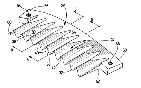
The knife 16 which is typical comprises a blade 24 and a
' ' '
.. -.
. :: .
. . .
~ . , . .. : . .
132793~
shank 26 integrally formed of steel as apparent, for exarnple, in figs. 3 and 4.These are made by casting the metal in the required configuration and then
machining the surfaces of the casting. The blade 24 may be seen to comprise
opposing inner and outer blade surfaces 28,30 which meet in angled
5 relationship (forrning an angle of between about 8 and 15,degrees) at a
forward blade portion to define a thin corrugated cutting edge 32. The peak-
to-peak amplitude of the corrugations of the cutting edge 32 might typically be
in excess of about one-eighth of an inch (actually about one-quarter inch in
the blade 24), making the blade 24 appropriate for production of relatively
10 thick lattice-cut potato slices.
Each of the opposing blade surfaces 28,30 has undulations
defming a set of elongate alternating grooves and ridges each commencing at
the cutting edge 32 and extending rearwardly from the cutting edge 32 to a
rear blade portion and ultimately terminating at the shank 26. The length of
15 the grooves might typically be between 1 and 2 inches while the lateral
spacing between adjacent groove bottoms or ridge tops at the colrugated
cutting edge 32 might typically be in the order of about one-half inch. A ridge
36 and adjacent groove 38 of the outer blade surface 30 are typical of the outerset and are shown in cross-section in the views of Figs. S and 6. The general
20 profiles of a typical groove 40 and adjacent ridge 42 associated with the inner
blade surface 28 are also apparent respectively in Figs. S and 6.
The opposing iMer and outer blade surfaces 28, 30 are
generally inclined relative to one another. The blade 24 consequently
becomes generally thicker in cross-section from the forward blade portion to
25 a rear blade pottion spaced from the forward blade portion. The difference inthickness between forward and rear blade portions will be apparent in the
cross-sectional view of Fig. S where points 44 and 46 associated respectively
- 6-
: . .
- . ~ " .,- , '
, ~
.. ..
- ~, . . .
.
1327~3~
with the for vard and rear blade portions are indicated, and also in Fig. 6 at
points 48 and 50 associated respectively with the forward and rear blade
portions. The blade 24 is accQrdingly quite rigid and sufficiently
self-supporting that it does not require clamping members on opposing faces
5 to ensure that the blade 24 retains a required configuration during slicing.
The relationship between bottoms of adjacent grooves on
opposing blade surfaces in this embodiment of the invention is apparent from
in fig. 10. The relationship between bottoms of the adjacent grooves 38,40
of the opposing blade surfaces is typical. The t vo grooves 38,40 initially
10 converge at the forward blade portion but diverge at the rear blade portion and
are spaced at the rear blade porlion, in a direction transverse to the blade
surfaces 28, 30, by a distance corresponding to about the peak-to-peak
amplitude of the corrugations of the cutting edge 32. The thickness of the
blade 24 in this region will tend to be in excess of the peak-to-peak amplitude. The divergence of the adjacent groove bottoms on the
opposing blade surfaces 28,30 and their spacing in this region permits the
shank 26 to be unobtrusively attached to the rear portion of the blade 24. It
will be apparent from figs.3-6 that the shank 26 lies between the opposing
blade surfaces 28,30, at the rear blade portion where these surfaces and their
20 grooves are significantly spaced-apart. The shank 26 has opposing inner and
outer shank surfaces 52,54 each meeting one of the opposing blade surfaces
28, 30 and the grooves formed in the blade surfaces. Each of the shank
surfaces 52, S4 is so inclined relative to the blade surfaces 28, 30,
respectively, that rearward ends of the blade grooves are directed outwardly
25 of the shank 26, ensuring that the shank 26 does not obstruct the grooves andconsequently the movement of either a potato being cut by the blade 24 or of a
.
~ - !
.
'' . ' ,:,` ~ ,. :.
~327934
slice being freshly cut from the potato (as apparent from figs. 8 and 9).
Basically, the divergence and separation of the opposing sets of grooves
provides a blade region where the shank 26 can be connected without
intruding into the grooves bottoms. In contradistinction, a shank of any
5 practical thickness cannot be connected to the rear of a conventional sheet-like
corrugated blade without intruding into the rearward ends of the opposing sets
of grooves.
The shank 26 has opposing tabs 56,58, one tab extending
laterally beyond each of the opposing sides 60, 62 of the blade 24. These
tabs 56,58 are formed with threaded apertures 64, 66 that permit the knife to
be mounted to the Urschel-type potato slicing machine 10, as with the Allen
screws 68, 70 apparent in figs. 2 and 7. Although the separation and
divergence of the opposing groove bottoms at ~e rear blade portion permits
unobtrusive attachment of the shank 26 to the rear blade portion, the same
general configuration also provides a sufficienay thick and robust blade that
the shank might be eliminated in favor of laterally-extending mounting tabs
formed with or secured directly to the rear blade portion itself.
The manner in which a potato can be cut to produce a
lattice-cut potato slice will be apparent from the cross-sectional view of Fig.
8 where the potato 22 is shown engaging the blade 24 of the knife 16. The
exposed surface 72 of ahe potato 22 is assumed previously to have been
formed with a first waffle-cut defining the grooves and ridges shown
extending transversely to the plane of the drawing page and to have been
rotated through 90 degrees to reach the orientation i11ustrated. As apparent in
~ig. 8, the amplitude of the corrugations is suffichnt to form deep grooves in
the potato slice and to define a lattice~shape. Details respecting angling of the
blade 24, selection of opening size and the like will be apparent from ahe
: . . -, . .
1327~3~
teachings of the prior Urschel patents which are incorporated herein by
reference.
A number of matters regarding the specific shape of the blade
24 and shank 26 should be noted. First, the outer blade surface 30 is
5 generally convex (essentially partffpherical) in side-to-side cross-section
while the inner blade surface 28 is generally concave (also essentially
part-spherical) in side-to-side cross-section. This is largely to allow the
blade 24 to conform generally to the part-spherical shape of the housing
sidewall 14 of the associated UIschel-type slicing machine 10. The shank
10 surfaces 52,54 are similarly configured for similar reasons.
With respect to the outer blade surface 30, it will be noted that
the tops of the ridges and the bottoms of the grooves are parallel and straight
(as apparent in Figs.5 and 8), as on the outer surface of a more conventional
sheet-like corrugated blade. The grooves and ridges of the inner blade
15 surface 28 might be similarly con~lgured, with the bottoms of the grooves
positioned flush with the inner surface 74 of the slicer sidewall 14. However,
as apparent in Fig. 9 where the typical inner groove 40 and ridge 42 are
illustMted in cross-section, the ridges and grooves of the inner blade surface
28 may be appropriately machined so that a potato being processed sees a
20 smoother transition between the inner blade surface 28 and the inner surface
74 of the cutter sidewall 14. In particular, the inner grooves curve Mdially
inwardly from the forward blade portion to the rear blade pc~on. The ridges
of the inner blade surface 28 are continuously reduced (by appropriate
machining) from the forward blade portion to the rear blade portion. The
25 curva~ure of the inner grooves and ridges and also that of the inner shank
surface S2 is wch that the inner surfaces presented by the knife to a potato
flows more smoothly into the inner housing surface 74, as apparent in Fig. 9.
, ~ . , .
. ~
- :: :, ~ , j . .
132793~
It will be appreciated that a par~cular embodiment of the
invention has been described and that modifications may be made therein
without necessarily departing from the spirit of the invention or the scope of
the appended claims.
- 10-
.., ,,.. ,, . , ~ . - . , .-,,
~ . . . . .. .. . . . . ..