Language selection

Search

Patent 1328061 Summary

Third-party information liability

Some of the information on this Web page has been provided by external sources. The Government of Canada is not responsible for the accuracy, reliability or currency of the information supplied by external sources. Users wishing to rely upon this information should consult directly with the source of the information. Content provided by external sources is not subject to official languages, privacy and accessibility requirements.

Claims and Abstract availability

Any discrepancies in the text and image of the Claims and Abstract are due to differing posting times. Text of the Claims and Abstract are posted:

  • At the time the application is open to public inspection;
  • At the time of issue of the patent (grant).
(12) Patent: (11) CA 1328061
(21) Application Number: 591278
(54) English Title: ELECTRONIC THROTTLE ACTUATOR
(54) French Title: COMMANDE ELECTRONIQUE DES GAZ
Status: Deemed expired
Bibliographic Data
(52) Canadian Patent Classification (CPC):
  • 123/3
(51) International Patent Classification (IPC):
  • F02D 41/00 (2006.01)
  • F02D 11/10 (2006.01)
(72) Inventors :
  • IMOEHL, WILLIAM JAMES (United States of America)
(73) Owners :
  • SIEMENS AUTOMOTIVE L.P. (United States of America)
(71) Applicants :
(74) Agent: BORDEN LADNER GERVAIS LLP
(74) Associate agent:
(45) Issued: 1994-03-29
(22) Filed Date: 1989-02-16
Availability of licence: N/A
(25) Language of filing: English

Patent Cooperation Treaty (PCT): No

(30) Application Priority Data:
Application No. Country/Territory Date
07/157,769 United States of America 1988-02-18

Abstracts

English Abstract


ELECTRONIC THROTTLE ACTUATOR

ABSTRACT OF DISCLOSURE

An electronic throttle actuator (10) is directly
connected without an intervening gear train to a stepper
motor (12) for rotating the throttle valve (16) from a
first position, closed or substantially closed, to a
second position which is wide open and any angular
position therebetween. The movement of the throttle valve
is under control of electronic control means (70) which
can locate the throttle valve at any one of a plurality of
positions between the fist and the second positions. The
coupling (24) between the motor and the shaft of the
throttle valve provides for redundant means to close the
throttle valve and connected to the shaft are a pair of
redundant torsion springs (30,32) for biasing the throttle
valve in said first position. A second coupling (38)
directly connects the shaft of the throttle valve to a
throttle position sensor (22). A pair of cavities (36,34)
are formed in the throttle body housing for enclosing both
the coupling from the shaft to the motor and to the
throttle position sensor and the redundant torsion
springs. Vent passages (40) communicate the cavities to
the throttle bore.


Claims

Note: Claims are shown in the official language in which they were submitted.


IT IS CLAIMED:

1. An electronic throttle (10) actuator for an internal
combustion engine comprising:
a throttle body housing (20);
a throttle bore (18) in said housing and extending
therethrough;
shaft means (14) mounted for rotation and extending
through said throttle bore from one wall to the
diametrically opposed wall;
a throttle blade (16) mounted on said shaft means and
rotatable therewith from a substantially closed position
to a substantially wide open position;
a torsion spring (32) biasing said shaft means in a
rotatable direction to position said throttle blade in
said substantially closed position;
cavity means (36) in said housing for receiving one
end of said shaft means and enclosing said torsion spring;
motor means (12) mounted on said throttle body
housing;
coupling means (24) for gearlessly coupling said
motor means to said shaft means; and
electronic control means (70) for operating said
motor to rotate said shaft means.

2. An electronic throttle actuator for an internal
combustion engine according to Claim 1 additionally
including a throttle position sensor means (22)
operatively coupled to said shaft means for indicating the
angular position of said throttle blade.

3. An electronic throttle actuator for an internal
combustion engine according to Claim 2 additionally having


a second cavity (34) in said housing for receiving the
other end of said shaft means.

4. An electronic throttle actuator (10) for an internal
combustion engine comprising:
a throttle body housing (20);
a throttle bore (18) in said housing and extending
therethrough;
shaft means (14) mounted for rotation and extending
through said throttle bore from one wall to the
diametrically opposed wall;
a throttle blade (16) mounted on said shaft means and
rotatable therewith from a substantially closed position
to a substantially wide open position;
a torsion spring (30) biasing said shaft means in a
rotatable direction to position said throttle blade in
said substantially closed position;
cavity means (36) in said housing for receiving one
end of said shaft means and enclosing said torsion spring;
motor means (12) mounted on said throttle body
housing;
coupling means (24) for gearlessly coupling said
motor means to said shaft means;
electronic control means (70) for operating said
motor means to rotate said shaft means,
additionally including a throttle position sensor
means (22) operatively coupled to said shaft means for
indicating the angular position of said throttle blade,
additionally including a second cavity means (34) in
said housing for receiving the other end of said shaft
means, and
additionally including coupling means (38) located in
said second cavity means for directly coupling said shaft
means to said throttle position sensor means.


5. An electronic throttle actuator for an internal
combustion engine according to Claim 4 wherein said
coupling means (38) for directly coupling said shaft means
to said throttle position sensor means comprises:
a sensor face plate means (69) connected to said
throttle position sensor means,
a shaft face plate means (68) connected to one end of
said shaft means, and
means (64) interconnecting said sensor face plate
means and said shaft face plate means.

6. An electronic throttle actuator for an internal
combustion engine according to Claim 3 additionally
including a torsion spring means (32) connected to each
end of said shaft and respectively located within said
dual cavities respectively.

7. An electronic throttle actuator (10) for an internal
combustion engine comprising:
a throttle body housing (20);
a throttle bore (18) in said housing and extending
therethrough;
shaft moans (14) mounted for rotation and extending
through said throttle bore from one wall to the
diametrically opposed wall;
a throttle blade (16) mounted on said shaft means and
rotatable therewith from a substantially closed position
to a substantially wide open position;
a torsion spring (32) biasing said shaft means in a
rotatable direction to position said throttle blade in
said substantially closed position;
cavity means (36) in said housing for receiving one
end of said shaft means and enclosing said torsion spring;


11

motor means (12) mounted on said throttle body
housing;
coupling means (24) for gearlessly coupling said
motor means to said shaft means;
electronic control means (70) for operating said
motor means to rotate said shaft means, and
said electronic throttle actuator additionally having
vent means (40) extending from said throttle bore to said
cavity means.

8. An electronic throttle actuator for an internal
combustion engine according to Claim 1 wherein said means
(24) for gearlessly coupling said motor means to said
shaft means comprises:
a motor face plate means (42) connected to the shaft
of said motor means,
a shaft face plats means (44) connected to one end of
said shaft means, and
means (64) interconnecting said motor face plate
means and said shaft face plate means.

9. An electronic throttle actuator (10) for an internal
combustion engine comprising:
a throttle body housing (20);
a throttle bore (18) in said housing and extending
therethrough;
shaft means (14) mounted for rotation and extending
through said throttle bore from one wall to the
diametrically opposed wall;
a throttle blade (16) mounted on said shaft means and
rotatable therewith from a substantially closed position
to a substantially wide open position;


12

a torsion spring (32) biasing said shaft means in a
rotatable direction to position said throttle blade in
said substantially closed position;
cavity means (36) in said housing for receiving one
end of said shaft means and enclosing said torsion spring;
motor means (12) mounted on said throttle body
housing;
coupling means (24) for gearlessly coupling said
motor means to said shaft means;
electronic control means (70) for operating said
motor means to rotate said shaft means, and
wherein said means (24) for gearlessly coupling said
motor means to said shaft means comprises:
a motor face plate means (42) connected to the
shaft of said motor means,
a shaft face plate means (44) connected to one end
of said shaft means, and
means (64) interconnecting said motor face plate
means and said shaft face plate means; and
wherein said means (64) interconnecting said motor
face plate means and said shaft face plate means
comprises:
a pair of diametrically opposed tangs (64,66)
extending from said shaft face plate means;
a "U" shaped slot (52) in said motor face plate
means for receiving one of said tangs; and
a lever (58) on said motor face plate means
operable to engage the other of said tangs.

10. An electronic throttle actuator for an internal
combustion engine according to Claim 8 wherein said shaft
face plate means (44) has a lever (62) extending from one
surface thereof for engaging said torsion spring (32) for
biasing said shaft means (16) to a given angular position.


13

11. An electronic throttle actuator for an internal
combustion engine according to Claim 1 wherein said
electronic control means (70) is mounted on said throttle
body housing (20) and enclosed by a plate means (76).

12. An electronic throttle actuator for an internal
combustion engine according to Claim 1 wherein said shaft
means (14) is offset from the center of the throttle bore
for biasing said throttle blade (16) in a closed
direction.

13. A coupling for directly coupling a drive and a driven
shaft providing redundant drive in one rotational
direction and single drive in the other rotational
direction, said coupling comprising:
a drive shaft face plate means (42) connected to the
drive shaft,
a driven shaft face plate means (44) connected to one
end of the driven shaft,
a pair of diametrically opposed tangs (64,66)
extending from said driven shaft face plate means;
a "U" shaped slot (52) in said drive face plate means
for receiving one of said tangs, one side of said "U"
shaped slot for rotating said tang in one rotational
direction and the other side of said "U" shaped slot for
rotating said tang in the other rotational direction; and
a lever (58) on said drive face plate means operable
to engage the other of said tangs for rotating said other
of said tangs in only one direction.

14. An electronic throttle actuator (10) for an internal
combustion engine comprising in combination:
a throttle body housing (20);


14
a throttle bore (18) in said housing and extending
therethrough;
throttle valve means (16) disposed in said throttle
bore;
journal means (26,28) for journaling said throttle
valve means (16) on said throttle body for rotatable
motion about an axis that is transverse to said throttle
bore, said journal means including a shaft means (14) that
supports said throttle valve means and that passes through
and beyond respective holes in said throttle body housing
on opposite sides of said throttle bore;
first closure means (37) cooperating with said
throttle body housing in forming a first cavity (36)
containing that portion of said shaft means which has
passed beyond a first of said holes;
second closure means (35) cooperating with said
throttle body housing in forming a second cavity (34)
containing that portion of said shaft means which has
passed beyond a second of said holes;
said first and second closure means respectively
including a motor means (12) and a throttle position
sensor means (22) respectively;
first coupling means (24) disposed within said first
cavity for operatively coupling said motor means with said
shaft means so that operation of said motor means is
effective to position said throttle valve means about said
axis;
and second coupling means (38) disposed within said
second cavity for operatively coupling said shaft means
with said throttle position sensor means so that said
throttle position sensor means is effective to provide a
signal indicative of the position of said throttle valve
means about said axis.


15. In an electronic throttle actuator (10) for an
internal combustion engine, the combination comprising:
a throttle body housing (20);
a throttle bore (18) in said housing and extending
therethrough;
throttle valve means (16) disposed in said throttle
bore;
journal means (26,28) for journaling said throttle
valve means on said throttle body for rotatable motion
about an axis that is transverse to said throttle bore;
said journal means including a shaft (14) that
supports said throttle valve means and that passes through
and beyond a hole in said throttle body housing;
closure means (35) cooperating with said throttle
body housing in forming a cavity (34) containing that
portion of said shaft which has passed beyond said hole,
said closure means including an electromechanical device
(22) that is associated with the electronic throttle
actuator;
coupling means (38) disposed within said cavity
operatively coupling said electromechanical device (22)
with said shaft so that said electromechanical device and
said shaft operate in unison;
and vent passage means (40) that is separate from
said hole and communicates said cavity to said throttle
bore.

Description

Note: Descriptions are shown in the official language in which they were submitted.


. 12RCW0288 ~046a 580-87-0070
--1-- .

1328~61 ~`

ELECTRO~IC THROTTL~ ACTUATOR

This invention relates to electronic control
~y~tems for internal combustion engines in qeneral and
5 more particularly to electrically actuated throttle body
assemblies.

BACRGROU~D OF THE I~VEDTIO~
Conventional control of a throttle in an internal
10 combustion engine involves a series of links and
linkages from a foot pedal in the passenger compartment
of a motor vehicle to the butter~ly valve or throttle
blade in the air intake of the eng~ne. Each link and
pivot posit~on prbvi~es a source for misadjustment and
15 failure. Failure because of corrosion and dirt between
the pivot surface~ and misad~u~tment because of wear and
loosenes~ in the connection of the links.

~UMMARY 0~ TH~ IJVEDTIO~
Drive-by-wire or olectronic throttle control iB a
concept where the motion of the foot pe~al or throttle
control in the operator compartment of the vehicle is
transferred by electrical signals to an actuator for
moving the butt~rfly valve. The actuator in most
25 instances i8 a d.c. motor which rotates through a syætem
of gears the throttls blade from a substantially closed
throttle position to a wide open throttle position.
Positlonihg i~ determined in a servo controlled manner.
The main advantage of this electronic throttle
30 actuator i~ a mechanical ~ystem using a stepper motor
directly coupled to the throttle blade ~haft without any
intervening qears which may wear or break.
Another advantage of the present system is an
electronic gear reduct~on unlt which is capable of
35 converting 1.8 of throttle movement into .056 steps.
~: .

,~ .
7~ . - .

12RCW0288'~046a 580-87-0070
-2-

1328~61
Other advantages will become apparent from the
electronic throttle actuator for an internal combustion
engine having a throttle body housing with a throttle
bore e~tending therethrough. A shaft means is mounted
5 for rotation and estends through the throttle bore from
one wall to the diameterically opposed wall. A throttle
blade is mounted on the ~haft means and is rotatable
therewith from a substantially closed position to a
substantially wide open position depending upon the
l0 system design ~pecifications. At least one torsion
spring biases the ~haft means in a rotatable direction
~o position the throttle blade in the substantially
closed po~ition. A cavity means i8 formed in the
housing for enclosing the torsion spring. A motor is
lS mounted on the throttle body housing and is directly
coupled without any intervening gear reduction means to
the shaft means. Electronic control means is
operatively connected for operating the motor to rotate
the ~haft means and hence the butterfly valve to control
20 the flow air into the engine.
Many other a~vantages and purpo~e~ of the invention
will be clear from the following detailed de~cription of
the drawings.

25 DETAILED DE~CRIPTIO~ OF THE DRaWI~G~
In the drawings:
Figure 1 is top view of the electronic throttle
actuator.
Figure 2 i8 a sectional view taken along line 2-2
30 of Figure 1.
Figure 3 is a sectional v~ew taken along line 3-3
of Figure 1.
Figure 4 i~ a top view of another embodiment of the
electronic throttle actuator showing the electronic
35 control package mounted thereon.

12RCW0288 '~046a 580-87-0070

1328061

DErAILED DESCRIPTIO~
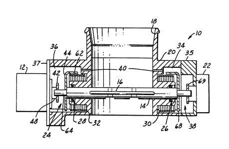
Referring to Figure 1 there is shown a top view of
an electronic throttle actuator 10 according to the
preferred embodiment. The actuator lo has a motor 12
5 connected to the shaft 14 of the throttle blade or
butterfly ~alve 16. The buttlerfly val~e 16 is located
in the air intake or throttle bore 18 in the throttle
body housing 20. In order to provide positioning
readout of the butterfly ~alve 16, a throttle position
10 sensor 22 i8 located at the end of the shaft 14 of the
throttle blade 16 opposite the motor 12.
As will be described, it will be obvious that the
only changes necessary to adapt the preferred embodiment
for different engines i8 to change the various sizes of
15 the components to accomodats the various throttle bore
diameters 18 and mounting holes. The motor 12 and the
throttle position sensor 22 are adequate for most all
engine ~izes.
Fi~ure 2 is a sectional view taken along line 2-2
20 of Figure 1 which i~ essentially along the a~is of the
butterfly valve ~haft 14. The throttle body 20 has the
air intake bore 18 which i8 adapted to receive an air
cleaner means, not shown, at one end and to discharge
the air lntake into the intake manifold, not shown, at
25 the other end. ~f desired, an air flow sensor maybe
connected in line with the air intake bore 18.
The motor 12, which i~ a d.c. stepper motor, is
directly`coupled to the throttle blade shaft 14 through
a coupling assembly 24 illustrated in Figure 3. The
30 throttle blade shaft 14 is mounted for rotation in a
pair of a~ially disposed seals 26, 28. The functio~ of
the seals 26, 28 i8 to keep dirt and corrosion from the
;~ bearinq surfaces of the shaft 14. 8ecured to the shaft
14 by con~en~ional means is the plate of the butterfl~
;~ 35 valve 16.
~ '

12RCWQ288J5046a 580-87-0070
--4--

1328~6~ ~ ~
At least one torsion or return spring 30 or 32 is
~ecured to the ~haft 14 for biasing the shaft in a
closed or gubstantially closed position. In the
preferred embodiment there are a pair of return springs
5 30, 32 ~scured to each end of the 6haft 14 and operate
to bias the buttlefly valve 16 to a closed postion or
substantially closed position. If the power is removed
from the motor 12, or there is a fracture in any of the
component~ of the throttle actuator 10, the torsion or
10 return springs 30, 32 will cause the shaft 14 to rotate,
closing the butterfly valve 16 to an idle speed or
closed position. The return ~prings 30, 32 provide a
failsafe redundancy to the actuator 10 in that either
spring 30, 32 has sufficient toræional forces to rotate
15 the ~haft 14.
The throttle body 20 has a pair of cavities 34, 36,
a sensor cavity 34 and a motor cavity 36, positioned at
each end of the shaft 14 for hou~ing the gprings 30, 32
and the coupling assemblie~ 24, 38. The purpose of the
20 cavities 34, 36 is keep the area clean from any e~ternal
contaminants such as dirt, water, screwdrivers, etc.
which may operate to cause fa~lure of the actuator 10.
A plate means 35, 37 attached to the housing 22 by
conventional means, not shown, encloses the cavities 34,
25 36. In addition, each of the cavities 34, 36 has a vent
40 to the air flowing through the throttle bore 18 which
air ha~ already passea through the engine air cleaner.
The air~flowing through the vents operates to prevent
contaminants from entering ~nto the cavitieg 34, 36
30 through pre~sure ~ifferential~ caused by leaks in ~he
butterfly valve ~haft seal~ 26, 28, temperature cycling
of air trappe~ in the cavities 34, 36, the throttle
position sensor 22 or the motor 12.

. 12RCW0288~046a 580-87-0070

, ~- . . .
1328Q61

In order to minimize the torque needed to open the
butterfly ~alve 16, the 6haft 14 i6 slightly offset from
the center of the throttle bore 18. Thi8 offset which
is from zero to ten thousandths of an inch (.0254 mm) ~.
5 operates to bias the butterfly valve 16 to close
reliably in the event of motor 12 failure, etc. wherein
the torsion springs 30, 32 supply the closing torque
necessary to rotate the shaft 14.
Referring to Figure 3 there is illustrated the
l0 coupling assembly 24 between the motor 12 and the shaft
14. A substantially similar coupling assembly 38 may be
used between the shaft 14 and the throttle position
sensor 22. The purpose of the coupling assemblies 24,
38 is to ensure direct drive of the shaft 14 from the
15 motor 12 and from the shaft 14 to the throttle position .
sensor 22 respectively. The coupling assembly 24
comprises a motor face plate 42, a shaft face plate 44
and a limit pin 46.
The motor f~ce plate 42 i8 directly connected to
20 the motor shaft 48 by conventional means such as a
~lotted aperture 50. In the illu~tration of Figure 3,
the motor face plate 42 is generally of an oblong shape
wherein at one on~ there is a ~U~ shaped opening 52.
One side of the ~U~ shaped opening 52 is an open drive
lever 54 and the other si~e i8 a clo~e drive lever 56.
The nomenclature of open and close refers to the
~; positioning of the butterfly valve 16. The other end of
the oblong shape has a redundant close drive lever 58.
The shaft face plate 44 is similarly an oblong
30 shape wherein at one end 60 of the long dimsnsion, there
is an e~tension 62 which receives one end of the return
spring 32 in the motor c~vity 36. The shaft face plate
44 i8 likewise ~ecured to the butterfly valve ~haft 14
~: by conventional me4ns such a~ ~lotted aperture. Along
':; ~ .'' '~


: -
.

1328~1
12RC~0288/5046a 580-87-0070
-- 6 --

the narrow sides of the shaft face plate 44 are a pair
of tangs 64, 66 formed in a direction toward the motor
face plate 42 when the coupling is assembled. One of
the tangs 64 is positioned in the opening of the "U"
shaped aperture 52 in the motor face plate 42. The open
drive lever 54 operates to bear against this tang 64 to
rotate the shaft 14 in the clockwise direction. The
diametrically opposite tang 66 is positioned to bear
against the redundant close drive lever 58 to close the
throttle butterfly valve under the urging of the springs
30 and 32. The limit pin 46 is used to prevent opening
of the throttle butterfly valve with the close drive
lever 56 against the tang 66 when the open drive level
54 or the tang 64 has failed. Note in the preferred
embodiment, there are redundant closing drive levers 56,
58, but only one open drive lever 54 to provide a
failsafe operation closing the throttle valve 16.
Located in the sensor cavity 34 is the second
coupling assembly 38. Secured to the shaft 14 by
conventional means such as a slotted aperture or by
means of pinning i8 a second shaft face plate 68. The
function of this second shaft face plate 68 is to
provide a drive connection for the return spring 30
located in the sensor cavity 34. The end of the shaft
14 i6 configured to mate through the sensor face plate
69 with the throttle position sensor 22. Such a
throttle position sensor may be that described in United
States Patent 4,355,293 issued on October 19, 1982 to
Barry J. Driscoll and entitled "Electrical Resistance
Apparatus Having Integral Shorting Protection" which is
assigned to a common aæsignee.


~ ~ :'' ~
..... ....

1~2~61
12RCW0288/5046a 580-87-0070

As this is an electronic throttle actuator, the
necessary electronics 70 as described in co-pending
Canadian application Serial No. 591,277 by Wright et al
entitled "Microstepping of an Unipolar D.C. Motor" may
be packaged and placed on the side of the throttle body
housing 20 as illustrated in Figure 4. In this manner,
the leads 72 from the motor 12 and the leads 74 from the
throttle position sensor 22 may be contained within the
electronics housing 76 and not exposed. The power
electronics may be positioned so as to have the heat
generated thereby transferred to the air flow through
the throttle bore 18. As illustrated in Figure 4, this
positions the power electronics along the thinnest wall
of the throttle bore 18. A connector, not shown, is
used to provide power and control signals to the
electronics 70 for operating the electronic throttle
actuator.
The combination of the electronics 70 as described
in the co-pending application and the design of the
coupling 24 between the motor 12 and the butterfly valve
16 provides a means to release a butterfly valve which
has been frozen or iced closed in the throttle bore 18.
The synchronization of the motor and the throttle
position sensor 22 causes the stepping motor to
06cillate until the ice has been dislodged and the
butterfly valve is freed.
Many changes and modifications in the above
described embodiment of the invention can, of course, be
carried out without departing from the scope thereof.
Accordingly, that scope is intended to be limited only
by the scope of the appended claims.


''~'

Representative Drawing
A single figure which represents the drawing illustrating the invention.
Administrative Status

For a clearer understanding of the status of the application/patent presented on this page, the site Disclaimer , as well as the definitions for Patent , Administrative Status , Maintenance Fee  and Payment History  should be consulted.

Administrative Status

Title Date
Forecasted Issue Date 1994-03-29
(22) Filed 1989-02-16
(45) Issued 1994-03-29
Deemed Expired 1997-04-01

Abandonment History

There is no abandonment history.

Payment History

Fee Type Anniversary Year Due Date Amount Paid Paid Date
Application Fee $0.00 1989-02-16
Registration of a document - section 124 $0.00 1989-05-01
Registration of a document - section 124 $0.00 1999-05-06
Owners on Record

Note: Records showing the ownership history in alphabetical order.

Current Owners on Record
SIEMENS AUTOMOTIVE L.P.
Past Owners on Record
ALLIEDSIGNAL INC.
IMOEHL, WILLIAM JAMES
SIEMENS-BENDIX AUTOMOTIVE ELECTRONICS L.P.
Past Owners that do not appear in the "Owners on Record" listing will appear in other documentation within the application.
Documents

To view selected files, please enter reCAPTCHA code :


To view images, click a link in the Document Description column. To download the documents, select one or more checkboxes in the first column and then click the "Download Selected in PDF format (Zip Archive)" or the "Download Selected as Single PDF" button.

List of published and non-published patent-specific documents on the CPD .

If you have any difficulty accessing content, you can call the Client Service Centre at 1-866-997-1936 or send them an e-mail at CIPO Client Service Centre.


Document
Description 
Date
(yyyy-mm-dd) 
Number of pages   Size of Image (KB) 
Representative Drawing 2002-02-25 1 15
PCT Correspondence 1993-09-07 1 19
Prosecution Correspondence 1991-11-06 2 36
Examiner Requisition 1991-07-19 1 38
Description 1994-07-22 7 462
Drawings 1994-07-22 2 91
Claims 1994-07-22 8 520
Abstract 1994-07-22 1 56
Cover Page 1994-07-22 1 45