Note: Descriptions are shown in the official language in which they were submitted.
~"
` `- ~328117
- 1 -
PROCESS
This invention relates to a liquid phase catalytic
hydrogenation process.
~ eterogeneous catalytic hydrogenation processes of
various kinds are widely practised on a commercial scale and
are used for hydrogenation of a wide variety of organic
feedstocks. Typically such hydrogenation reactions are
conducted at a pressure of from about 1 bar to about 300 bar
and at a temperature in the range of from about 40C to
about 380C. Examples include hydrogenation of aldehydes to
alcohols, of unsaturated hydrocarbons to saturated
hydrocarbons, of acetylene-derived chemicals to saturated
materials~ of unsaturated fatty acids to saturated fatty
acids, of ketones to secondary alcohols, of esters of
unsaturated fatty acids to esters of partially or fully
hydrogenated fatty acids, of nitriles to primary amines, and
of certain sugars to polyhydroxyalcohols. Also worthy of
mention is the hydrogenation of quinones, for example the
hydrogenation of 2-ethylanthraquinone as a step in the
production of hydrogen peroxide. This cyclohexanol is
produced commercially by catalytic hydrogenation of
cyclohexanone, and iso-propanol by catalytic hydrogenation
of acetone. An example of hydrogenation of an unsaturated
hydrocarbon is the production of cyclohexane from benzena.
Typical catalysts for such hydrogenation reactions include
Group VIII metal catalysts, such as nickel, palladium and
platinum. Production of butane-1,4-diol by hydrogenation of
but-2-yn-1,4-diol is an example of hydrogenation of an
acetylene-derived chemical. A suitable catalyst for this
reaction has been described as a granular nickel-copper-
manganese on silica gel. The production of stearic acid by
catalytic hydrogenation of the corresponding unsaturated
acids, linoleic acid and linolenic acid, at a temperature of
about 150C and at a pressure of about 14.75 bar to about 32
bar and using a nickel, cobalt, platinum, palladium,
' .
328~17
-- 2
chromium or copper/zinc catalyst, is an example of the
hydrogenation of unsaturated fatty acids to yield saturated
fatty acids. So-called "hardening" of vegetable oils is an
example of hydrogenation of esters of unsaturated fatty
acids. Production of beta-phenylethylamine by
hydrogenation of benzyl cyanide is an example of
hydrogenation of a nitrile. As examples of hydrogenation
of sugars to polyhydroxyalcohols there can be mentioned
hydrogenation of ketose and aldose sugars to
hexahydroxyalcohols, for example hydrog~nation of D-glucose
to sorbitol and of D-mannose to mannitol.
An important route ~o C3 and higher alkanols
involves hydroformylation of alpha-olefins, such as
ethylene, propylene, and butene-1, to yield the
corresponding aldehyde having one more carbon atom than the
starting olefin. Thus ethylene yields propionaldehyde and
propylene yields a mixture of n- and iso-butyraldehyde
(with the n-isomer usually predominating). These aldehydes
yield the corresponding alkanols, e.g. ~=propanol and n-
butanol, upon catalytic hydrogenation. The important
plasticiser alcohol, 2-ethylhexanol, is made by alkali-
catalysed condensation of n-butyraldehyde to yield the
unsaturated aldehyde, 2-ethyl-hex-2-enal, which is then
hydrogenated to yield the desired 2-ethylhexanol. Although
the preferred catalysts for such aldehyde hydrogenation
reactions used to be ~roup VIII metal catalysts, such as
nickel, palladium or platinum, the use of a solid catalyst
comprising a reduced mixture of CuO and ZnO under vapour
phase conditions has also been proposed (see European
Patent Application Number EP-A-0008767 published November
4, 1981 and United States Patent No. 2,549,416 issued April
17, 1951). Molybdenum sulphide supported on an activated
carbon carrier has also been suggested in GB-A-765972. The
hydrogenation of an aldehyde feed containing ring-type
sulphur compounds using a reduced mixture of oxides or
hydroxides of copper and zinc is described in U.S. Patent
No. 4,052,467 issued Oct. 4, 1977. Copper chromite has
also been used as an aldehyde hydrogenation catalyst.
~`` ' ` : ` ~ ' ' '' .
, ' . ~' ~ '~' - ' ' - -
: , ; . ,, .:-: .
.. ..
,
~328~17
:
-- 3
Hydrodesulphurization is another commercially
important hydrogenation reaction. This is the removal
complex organic sulphur compounds, such as sulphides,
disulphides, benzothiophene and the like, from a mixed
` 5 hydrocarbon feedstock by catalytic reaction with hydrogen
to form hydrogen sulphide. In such a process typical
;operating conditions include use of a temperature of from
about 260C to about 375C, a hydrogen pressure of from
about 5 bar to about 40 bar and an alumina supported
cobalt-molybdenum or nickel-molybdenum catalyst.
Catalytic hydrogenation is in all the above cases
a heterogeneous process. It may be operated as a liquid
phase process or as a vapour phase process. A review of
some of the factors involved in designing heterogeneous gas
and vapour phase reaction systems appeared in "Chemical
Engineering", July 1955, in an article entitled "Moving Bed
- Processes ... New Applications", at pages 198 to 206 (see
in particular pages 204 and 205 thereof~.
There have been various prior proposals to operate
hydrogenation processes in several catalytic stages
connected in series. For example, a vapour phase aldehyde
hydrogenation process is described in United States Patent
No. 4,451,677 issued May 29, 1984 which involves use of a
plurality of adiabatically operated catalytic hydrogenation
stages connected in series.
German Patent Application DE-B-1115232 published
-Oct. 19, 1961 describes a process for the production of
alcohols with 2 to 6 carbon atoms by hydrogenation in the
liquid phase over a nickel or cobalt catalyst of a feed
`~ 30 mixture comprising the corresponding aldehyde diluted with
~-,from 50 to 300 volume % of product alcohol, using two
hydrogenation stages connected in series. Reaction
conditions include use of a temperature of 130~C to 220C
~land a pressure of less than 50 bar, whilst the aldehyde
`''35 feed rate corresponds to a space velocity of from 0.3 to
`2.5 hr1, preferably 0.75 to 1.1 hr1. An excess of hydrogen
~jis recirculated from the exit end of the second
:, ,
, .
~ 32~117
:
-- 4
hydrogenation stage to the inlet end of the first
hydrogenation stage.
British Patent No. 784,359 published Oct. 9, 1957
is concerned with preferential hydrogenation of aldehydes
in a mixture of aldehydes and olefins, water being added to
inhibit olefin hydrogenation. Multi-bed co-current
hydrogenation is used, with injection of hydrogen between
beds. Hydrogen recycle is envisaged.
British Patent No. 1,175,709 published December 23,
1969 describes an apparatus for production of cyclohexane
by catalytic hydrogenation of benzene. Excess hydrogen is
recycled.
Use of 2-ethylhexanol as solvent to control the
temperature during hydrogenation of a mixture of 2-
ethylhexanal and lso-butyraldehyde is suggested in Chem.
Abs., 96 (1982) 51807h.
Canadian Patent No. 926,847 issued May 22, 1973
discloses in Example 2 a process in which a solution of 2-
ethylanthraquinone is passed through a tubular reactor in
co-current with hydrogen. United States Patent No.
3,009,782 issued Nov. 21, 1961 describes a similar process
in which the working solution is passed through a fixed bed
; of the hydrogenation catalyst at a rate of between 20 and
200 litres per minute per square foot of catalyst bed
cross-section (215.3 and 2152.8 litres per minute per
square metre of catalyst bed). A further modification of
this process is outlined in United States Patent No.
` 3,755,552 issued August 28, 1973 which recommends
hydrogenatiun in a hydrogenator shell containing a
plurality of substantially vertically oriented, laterally
positioned cylinders filled with catalyst wherein the ratio
of the diameter of a cylinder to the diameter of the
j catalyst particle is at least 15:1.
In conventional liquid phase multi-stage
-~ 35 hydrogenation processes the hydrogen-containing gas and the
material to be hydrogenated are fed through the plant in
co-current or in counter-current fashion. In order to
',
- : :
~,
:-. -. : :
1328~17
.
: - 4~ -
achieve good economy of hydrogen usage it is usual to
recycle gas within the plant. Hence in designing the plant
:account must be taken of the circulating inert gases (e.g.
N2, Ar, CH4
:, .
.,
.,
;~:
' ~
,
~`;
.`
.
.' . : :
:
. :....... .
~ ~ ~328~7
-- 5 --
and the like) which are inevitably present in the
circulating gas of a commercial plant. Moreover, it is
recognised in the art that hydrogen is relatively poorly
soluble in organic liquids and so one of the rate limiting
steps in a liquid phase hydrogenation process may be the
dissolution of hydrogen in the organic phase and its
subsequent migration through the liquid phase to the
catalyst surface. For this reason the use of high partial
pressures of hydrogen is often recommended, although often a
balance has to be struck by the plant designer between
additional process efficiency and the additional capital and
running costs associated with use of high pressures. An
extra factor to be considered is the additional cost of
using recirculating gas streams at high pressure which
contain significant levels of inert gases as well as
hydrogen. Hence the plant designer may have to sacrifice
efficiency of hydrogen utilisation in order to avoid the
waste of energy involved in recycling inert gases at high
pressures in excess of about 50 bar.
The term trickle bed reactor is often used to
describe a reactor in which a liquid phase and a gas phase
flow concurrently downward through a fixed bed of catalyst
particles while reaction takes place. At sufficiently low
liquid and gas flow rat~s the liquid trickles over the
packing in essentially a laminar film or in rivulets, and
the gas flows continuously through the voids in the bed.
This is sometimes termed the gas continuous region or
homogeneous flow and is the type encounter~d usually in
laboratory and pilot scale operations. As gas and/or liquid
flow rates are increased there is encountered behaviour
described as rippling, slugging or pulsing flow. Such
behaviour may be characteristic of the higher operating
rates encountered in commercial petroleum processing. At
high liquid rates and sufficiently low gas rates, the liquid
phase becomes continuous and the gas passes in the form of
" '
,
: ' , : . - ,: .~ .
:; :
` ~ 1328~7
- 6 -
bubbles; this is sometimes termed dispersed bubble flow and
is characteristic of some chemical processing in which
liquid flow rates are comparable to the highest encountered
in petroleum processing, but where gas/liquid ratios are
much less. Flow patterns and the transitions from one form
to another as a function of gas and liquid flow rates have
been described by several authors.
A useful general review of trickle bed reactors
and other multiphase reactors can be found under the hea~ing
"Reactor Technology" in "Kirk-Othmer Encyclopedia of
Chemical Technology", Third Edition, Volume 19, at pages 880
to 914. This states at page 892:
"Trickle-bed reactors have complicated and as yet
poorly defined fluid dynamic characteristics. Contacting
between the catalyst and the dispersed liquid film and the
film's resistance to gas transport into the catalyst,
particularly with vapor generation within the catalyst, is
not a simple function of liquid and gas velocities. Maximum
contacting efficiency is attainable with high liquid mass
j velocities, i.e. 1-5 kg/(m2.s) or higher in all sized units
however, 3-8 kg/(m~.s) is a more preferable range of liquid
mass velocities."
~l Assuming a specific gravi~y for an organic liquid
;, of approximately 0.8, these liquid velocities indicate that
maximum contacting efficiency is attainable at a superficial
i liquid velocity of 0.24 to 1.0 cm/sec Si.e. 3-8 kg/(m2.s)).
Fur~her reviews of the operation of trickle bed
reactors have appeared as follows:
1. "Trickle-bed reactors" by Charles N. Satterfield,
AIChE Journal, Vol. 21, No. 2 (March 1975), pages 209 to
~28;
2. "Chemical Reactor Design for Process Plants" by
1 H.F. Rase tl977), pages 698 to 711;
;~ 3. I'Multiphase Catalytic Packed-Bed Reactors" by
~ Hanns P. Hofmann, Catal. Rev.-5ci.Eng., 17(1), pages 71 to
:.
:: . ., ~ , ~ .
. .
; - . : . . . . .
. - . . .. : .. ~ ~
--\~
1~28~ 7
-- 7 --
117 ~1978);
4. "Encyclopedia of Fluid Mechanics" ~1986), Chapter
32 by Milorad P. Dudukovic and Patrick L. Mills, pages 969
to 1017, published by Gul Publishing Company, P.O. Box
2608, Houston, Texas 77001;
5. "Trickle-Bed Reactors", by Mordechay Herskowitz
and J.M. Smith, AIChE Journal, Vol. 29, No. 1 (January 1983)
pages 1 to 18; - -
6. "Hydroprocessing conditions affect catalyst shape
selection" by B.H. Cooper, B.B.L. Donnis, and B. Moyse,
. Technology, December 8, 1986~ Oil & Gas Journal, pages 39 to
44;
: 7. "Gas Liquid-Solid Reaction Engineering" by Y.T.
Shah and D. Smith, IChemE Symposium Series 87 (ISCRE 8);
~ 8. "Trickle-Bed Reactors: Dynamic Tracer Tests,
Reaction Studies, and Modeling of Reactor Performance" by
A.A. El-Hisnawi, M.P. Dudukovic and P.L. Mills, ACS
Symposium Series 196, Chemical Reaction Engineering ~1982),
pages 421 to 440;
9~ "Hydrodynamics and interfacial areas in downward
cocurrent gas-liquid flow through fixed beds. Influence of
the nature of the liquid" by B.I. Morsi, N~ Midoux, A.
. Laurent, and J.-C. Charpentier, International Chemical
Engineering, Vol. 22, No. 1, pages 142 to 151 (January
1982);
10. "Packing wetting in trickle bed reactors :
influence of the gas flow rate" by S. Sicardi, G. Baldi, V.
Specchia, I. Mazzarino, and A. Gianetto, Chemical
Engineering Science, Vol. 36, pages 226 to 227 (1981);
11. "Influence of gas velocity and packing geometry on
pulsing inception in trickle-bed reactors" by S. Sicardi and
~; H. Hofmann, The Chemical Engineering Journal, 20 (1980),
pages 251 to 253;
12. "Some comments on models for evaluation of
catalyst effectiveness factors in trickle-bed reactorsn by
~`
:
;
`~ .
:, ... . .
:- . . :
1328117
-- 8 --
P.L. Mills, H.F. Erk, J. Evans~ and M.P. Dudukovic, Chemical
Engineering Science, ~1981), Vol. 36 ~5), pages 947 to 950;
13. "Effectiveness Factors and Mass Transfer in
Trickle-Bed Reactors" by Mordechay Herskowitz, R.G.
Carbonell and J.M. Smith, AICh~ Journal Vol. 25, No. 2
~March 1979) pages 272 to 283;
14. "Flow Regime Transition in ~rickle-Bed Reactors"
by S. Sicardi, H. Gerhard and H. Hoffmann, The Chemical
Engineering Journal, 18 (1979), pages 173 to 182;
15. "Catalyst Effectiveness Factor in Trickle-Bed
Reactors" by M.P. Dudukovic and P.L. Mills, Chemical
Reaction Engineering - Houston, ACS Symposium Series 65
(1978), pages 387 to 399;
16. "Hydrodynamics and Solid-Liquid Contacting
Effectiveness in Trickle-Bed Reactors" by A. Gianetto, G.
Baldi, V. Specchia, and S. Sicardi, AIChE Journal, Vol. 24,
No. 6, (November 1978~, pages 1087 to 1104;
17. "Analysis of Three-Phase Packed-Bed Reactors" by
~i
s. Goto and J.M. Smith, AIChE Journal, Vol. 24, No. 2, pages
295 to 302;
18. "Performance of Slurry and Trickle-Bed Reactors:
Application to Sulfur Dioxide Removal~, by S. Goto and J.M.
Smith, AIChE Journal, Vol. 24, No. 2, March 1978 pages 286
to 293;
19. "Two-Phase Downflow Through Catalyst Beds: Part 1.
Flow Maps" by E. Talmor, AIChE Journal, Vol. 23, No. 6,
November 1977, pages 868 to 878;
20. "Pressure Drop and Liquid ~oldup for Two Phase
Concurrent Flow in Packed Beds" by V. Specchia and G. Baldi,
Chemical Engineering Science, Vol. 32, (1977~ pages 515 to
`
523;
l 21. "Trickle-Bed Reactor Performance: Part 1. Holdup
and Mass Transfer Effects" hy S. Goto and J.M. Smith, AIChE
`I Journal, Vol. 21, No. 4, July 1975, pages 706 to 713;
22. "Effect of Holdup Incomplete Catalyst Wetting and
.
.1 .
9 13281~7
Backmixing during ~ydroprocessing in Trickle Bed Reactors"
by J.A. Paraskos, J.A. Frayer and Y.T. Shah, Ind. Eng.
Chem., Process Des. Dev., Vol. 14, No. 3, (lg75~ pages 315
to 322;
23. "Wetting of Catalyst Particles under Trickle Flow
Conditions" by J-B Wijffels, J. Verloop and F.J. Zuiderwegt
Chemical Reaction Engineering-II, Advances in Chemistry
Series, Vol. 133, 1974, pages 151 to 163;
24. "The Role of Liquid Holdup and Effective Wetting
in the Performance of Trickle-Bed ReactorsR by D.E. Mears,
Chemical Reaction Engineering-II, Advances in Chemistry
Series, Vol. 133, 1974 pages 218 to 227;
25. "Scale Up of Pilot Plant Data for Catalytic
Hydroprocessing" by H.C. ~enry and J.B. Gilbert, Ind. Eng,
Chem. Process Des. Develop., Vol. 12, No. 3, 1973, pages 328
to 334;
26. "Direct Solid-Catalyzed Reaction of a Vapor in an
; Apparently Completely ~etted Trickle Bed Reactor" by C.N.
Satterfield and F. Ozel, AIChE Journal, Vol. 19, No~ 6,
November 1973, pages 1259 to 1261;
i 27. "Pressure Loss and Liquid Holdup in Packed Bed
..i
Reactor with Cocurrent Gas-Liquid Down Flow" by Y. Sato, T.
Hirose, F. Takahashi, and M. Toda, Journal of Chemical
Engineering of Japan, Vol. 6, No. 2, 1973, pages 147 to 152;
28. "Partial Wetting in trickle bed reactors - the
reduction of crotonaldehyde over a palladium catalyst", by
W. Sedriks and C N. Kenney, Chemical Engineering Science,
Vol. 28~ 1973~ pages 559 to 568;
29. "Handling kinetics from trickle-phase reactors" by
A. Bondi, ChemO Tech., March 1971r page~ 185 to 188;
30. "Kinetics of Hydrodesulfurization~ by C.G. Frye
and J.F. Mosby, Chemical Engineering Progress, Vol. 63, No.
9, September 1967~ pages 66 to 70; and
31. "Performance of Trickle Bed Reactors" by L~D.
Ross, Chemical Engineering Progress, Vol. 61, No. 10,
, . .
. . - . . ~ ,
-- 10 --
October 19~5, pages 77 to 82.
The present invention seeks $o provide an improved
liquid phase hydrogenation process in which essentially 100%
hydrogenation of the aldehyde or other organic feedstock to
the desired hydrogenation product can be achieved, with
minimisation of formation of by-products.
It further seeks to provide a liquid phase
hydrogenation process in which the use of gas recycle
compressors is obviated. Additionally it seeks to provide a
process for liquid phase hydrogenation of a wide variety of
organic feedstocks which can be operated with excellent
economy of hydrogen usage without the need for recycle of
hydrogen-containing gases.
According to the present invention there is
provided a liquid phase catalytic hydrogenation process in
which an organic feedstock is contacted with hydrogen in the
presence of a solid hydrogenation catalyst under
hydrogenation conditions to produce a hydrogenation product,
which process comprises passing a feed solution of the
organic feedstock in an inert diluent therefor downwardly in
co-current with a hydrogen containing gas through a
hydrogenation zone containing a bed of a particulate
hydrogenation catalyst whose particles substantially all lie
in the range of from about 0.5 mm to about 5 mm, maintaining
the bed of catalyst particles under temperature and pressur~
conditions conducive to hydrogenation, recovering from a
bottom part of the bed a liquid phase containing the
hydrogenation product, controlling the rate of supply of the
feed solution to the bed so as to maintain a superfi~ial
liquid velocity of the liquid down the bed iD the range of
from about 1.5 cm/sec to about 5 cm/sec, and controlling the
rate of supply of the hydrogen-containing gas to the bed so
as to maintain at the top surface of the bed of catalyst
particles a flow of hydrogen-containing gas containing from
1.00 to about 1.15 times the stoichiometric quantity of
',
: ~'
`
'
~3~117
hydrogen theoretically necessary to convert the organic
feedstock completely to the hydrogenation product.
Preferably the catalyst particle size range is
from about O.5 mm to about 3 mm.
In view of the teaching in the art that, in
operation of trickle bed reactors, the maximum gas-liquid
contacting efficiency is attainable at a superficial liquid
velocity of no more than about l.O cm/sec, it is most
surprising to find that, in hydrogenation reactions such as
the hydrogenation of an aldehyde to an alcohol, an
approximately stoichiometric quantity of hydrogen, or at
most only a minor excess of hydrogen, can be used to achieve
near quantitative hydrogenation in a single passage over a
bed of catalyst of the appropriate depth when the catalyst
particle size range is from about 0.5 mm to about 5 mm and a
high liquid superficial velocity down the bed, i.e. from
about 1.5 cm/sec to about 5 cm/sec, is used. Thus, even
though the gas near the exit end of the bed may be almost
entirely depleted of hydrogen, efficient conversion of
unsaturated organic compound ~e.g. aldehyde) or other
organic feedstock to hydrogenation product (e.g. alcohol)
can be achieved without having to have recourse to high
pressures in excess of about 50 bar. Hence the use of a
large excess of hydrogen is not necessary as we have shown,
in the course of our experimentation, that the influence of
hydrogen partial pressure on the rate of hydrogenation is of
minor significance. Moreover in our work on hydroyenation
of aldehydes we have found that, under the unconventional
flow conditions used in the process of the invention, high
average rates of reaction are possible, approaching in
suitable cases about 5 gmO moles of aldehyde hydrogenated
per litre of catalyst per hour and at the same time
achieving substantial conversion (i.e. 95% of more) of the
aldehyde feed to the alcohol product.
The process of the invention is not specific to
,;` ,
,
- \
1328117
- 12 -
any particular hydrogenation reaction or to any particular
catalyst composition. However, in general the hydrogenation
conditions used in the hydrogenation zone include use of a
pressure of from about 1 bar to about 300 bar, often from
about 1 bar to about 100 bar, and of a temperature of from
about 40C to about 350C, often from about 90C to about
220C
In operating the process of the invention a
pressure drop is set up across the catalyst bed, typically
of at least about 0~1 kg/cm2 per metre of catalyst bed
depth. Care must accordingly be taken, in designing a plant
to operate according to the invention, that it is ensured
that at the bottom of the catalyst bed the crushing strength
of the catalyst is not equalled or exceeded. If there is
any risk of this occurring, then it is necessary to utilise
two or more catalyst beds of appropriate depth in place of a
single large catalyst bed; in this case gas and liquid must
be uniformly distributed into each bed.
The selection of catalyst particle size and of the
superficial liquid velocity are features which are crucial
to the process of the invention. These features ensure that
the catalyst surface is completely wetted, that a large
catalyst superficial surface area is presented for reaction
of the unsaturated organic compound or other organic
feedstock with hydrogen, that good liquid~gas contact is
effected as the gas bubbles entrained in the liquid pass
through the irregular channels in the bed in co-current
downflow through the bed, that dissolution of hydrogen into
the downflowing liquid is thereby facilitated, and that good
mass transfer of the dissolved hydrogen and unsaturated
organic compound or other organic feedstock to the catalyst
surface is also achiev~d by the relatively rapid flow of the
liquid through the complex network of interconnecting
passages present in the catalyst bed. In the case of
spherical catalyst particles the actual velocity of the
.
:
,.
,
~3281~7
- 13 -
liquid over the catalyst surface can be up to about 3 times
the superficial velocity of the gas plus liquid. Another
important factor is the concentration of the unqaturated
organic compound or other organic feedstock in the liquid
phase. As hydrogenation is usually an exothermic reaction,
the use of an appropriately dilute solution helps to limit
the temperature rise, particularly when the hydrogenation
zone is operated under adiabatic conditions. By selection
of an appropriate concentration of unsaturated organic
compound or other organic feedstock in the feed solution it
is pos~ible to optimise hydrogenation conditions at the
catalyst surface so that neither the unsaturated organic
compound or other organic feedstock nor any hydrogenation
product thereof "blinds" the catalyst to hydrogen. Such
"blinding" of the catalyst will occur, it is postulated, if
one or more of the species present, whether the unsaturated
organic compound or other organic feeds~ock or some
hydrogenation product thereof, is strongly absorbed or
adsorbed on the catalyst surface and thereby prevents
approach of hydrogen molecules to the active catalytic
sites.
The process of the invention can be applied, for
example to the hydrogenation of unsaturated hydrocarbons to
saturated hydrocarbons. Typical of such a reaction is the
production of cyclohexane from benzene. This hydrogenation
can be carried out according to the invention using a
nickel, palladium or platinum catalyst in the hydrogenation
zone and a temperature of from about 100C to about 200C
and a pressure of from about 5 bar to about 30 bar. This
reaction is exothermic. The use of relatively high
temperatures is normally recommended so as to maximise the
rate of conversion of benzene to cyclohexane, but
isomerisation of cyclohexane to methyl cyclopentane, which
is extremely difficult to separate from cyclohexane, can
occur in the aforementioned conventional procedures,
'
.
::
. ~ ~ ., . -. . . .
.
~328117
- 14 -
especially at such relatively high temperaturesO
Production of secondary alcohols by reduction of
ketones is another appropriate hydrogenation reaction to
which the invention can be applied. Examples of such
reactions include production of _ o-propanol from acetone
and of cyclohexanol from cyclohexanone.
Another example of a hydrogenation reaction to
which the present invention can be applied is the production
of butane-1,4-diol by hydrogenation of but-2-yn-1,4-diol.
This can be carried out using a catalyst which is a granular
nickel-copper-manganese on silica gel at a pressure of from
about 200 bar to about 300 bar in the hydrogenation zone. A
typical inlet temperature to the hydrogenation zone is about
40C, when the catalyst is freshly reduced.
A further example of a hydrogenation reaction to
which the process of the invention can be applied is the
production of stearic acid by hydrogenation of linoleic
acid, of linolenic acid, or of a mixture thereof. This can
be carried out using a nickel, cobalt, platinum, palladium,
chromium or zinc catalyst at a pressure of from about 10 bar
to about 40 bar and an inlet temperature to the
hydrogenation zone of about 150Co
Other examples of hydrogenation processes to which
the invention can be applied include "hardening" of
vegetable oils, hydrodesulphurization, hydrogenation of
nitriles to amines, and hydrogenation of sugars, (for
example, hydrogenation of aldoses, such as D-glucose or D-
mannose, to the correspondin~ hexahydroxyalcohols, such as
sorbitol and mannitol).
A particularly preferred type of hydrogenation
reaction is the production of alcohols from aldehydes. Such
aldehydes generally contain from 2 to about 20 carbon atoms
and may in the case of those aldehydes containing 3 or more
carbon atoms include one or more unsaturated carbon-carbon
bonds besides the unsaturated -C~O group. Thus as used
: ~ , ' ~ '
.
1 32811 7
- lS -
herein the ~erm "aldehyde" includes both saturated and
unsaturated aldehydes, that is to say aldehydes wherein the
only hydrogenatable group is the aldehyde group, -C~0,
itself ~such as alkanals) and aldehydes which contain
further hydrogenatable group such as olefinic groups,
>C - C<, in addition to the aldehyde group, -CH0 (such as
alkenals). Typical aldehydes include n- and iso_
butyraldehydes, n-pentanal, 2-methylbutanal, 2-ethylhex-2-
enal, 2-ethylhexanal, 4-t-butoxybutyraldehyde, C10-''OXOn-
aldehydes (e.gO 2-propylhept-2-enal), undecanal, dodecanal,
tridecanal, crotonaldehyde and furfural, as well as mixtures
of two or more thereof. Aldehydes and mixtures of aldehydes
can be produced by hydroformylation of an olefin or mixed
olefins in the presence of a cobalt catalyst or a rhodium
complex catalyst, according to the equation:
-C~-CH2 + H2 + C0 ---> R-CH2.CH2.CH0 ~ R.C~(CH0).CH3;
where R is a hydrogen atom or an alkyl radical. The ratio
of the n-aldehyde to the iso-aldehyde in the product depe~ds
to a certain extent on the selected hydroformylation
conditions and upon the nature of the hydroformylation
catalyst used. Although cobalt catalysts were formerly
used, more recently the use of rhodium complex catalysts ha
been preferred since these offer the advantages of lower
operating pressure, ease of product recovery, and high n-
/iso-aldehyde molar ratios. Typical operating conditions
for such rhodium complex hydroformylation catalysts can be
found in United States patent number 3,527,809 issued
September 8, 1970; United States patent number 4,148,830
issued April 10, 1979; European patent application number
EP-A-0096986, European patent application number EP A-
0096987 and European patent application number EP-A-
0096988, all published December 28, 1983. In such
hydroformylation processes the aldehyde or aldehyde
products can be recovered in admixtuxe with unreacted
.,
:
,
:
.~. ' ~ ~, :, , ,
'~ ~ : - ' j
`` ~ 328~17
- 15a -
olefin and its hydrogenation product, i.e. the
corresponding paraffin. Such crude reaction products can
be used as starting material in the process of the
invention. Further aldehydes can be obtained by
condensation reactions; for example, 2-ethylhex-2-enal can
be made by condensation of 2 moles of n-butyraldehyde
:'
.~ .
~'.
'~'' .
, '` ' ' : " ' '
' ' , `'; ', '. ;;' '" "
' ' . , ~ ' '
~3281~7
~ 16 -
and 2-propylhept~2-enal by condensation of 2 moles of n-
valeraldehyde. Examples of aldehyde hydrogenation reactions
are the production of n-butanol from n-butyraldehyde, of 2-
ethylhexanol from 2-ethylhex-2-enal, or 2~propylheptanol
from 2-propylhept-2-enal, of undecanol from undecanal, and
of 4-t-butoxybutanol from 4-t-butoxybutyraldehydeO The
invention is used to special advantage for hydrogenation of
aldehydes CQntaining from about 7 to about 17 carbon atoms
to the corresponding alkanols. In such aldehyde
hydrogenation reactions there can be used any of the
conventionally used supported metal catalysts, such as Ni~
Pd or Pt supported on a variety of supports such as granular
carbon, silica, silica-alumina, zirconia, silicon carbide or
the like, or copper chromite.
Other aldehyde hydrogenation catalysts include
cobalt compounds; nickel compounds which may contain small
amounts of chromium or another promoter; mixtures of copper
and nickel and/or chromium; and other Group VIII metal
catalysts, such as Pt, Pd, Rh and mixtures thereof, on
supports, such as carbon, silica, alumina and silica-
alumina. The nickel compounds are generally deposited on
support materials such as alumina or kieselguhr.
In all cases the catalys~ particles substantially
all have a particle size in the ranqe of from about 0.5 mm
to about 5 mm, preferably in the range of from about 0.5 mm
to about 3 mm, as measured by a conventional sieve analysis
techniqueO By the term "substan~ially all~ we mean that not
more than about 5%, and preferably not more than about 0.5%,
,;
of particles are less than about 0.5 mm in size, and that
not more than about 5~, and preferably not more than about
1%, of particles are larger than 5 mm (or 3 mm) in size.
The catalyst par~icles may be of any desired shape, such as
cylindrical, but are conveniently approximately spherical
granules. Eiow~ver the use of pelleted catalysts and of
catalyst particles of more complex shape is not ruled out.
..
;. , , ~ , ~. - : : .
.. ~ .
- ` 132~117
- 1: ~
In the case of spherical or granular catalyst particles the
i particle size is essentially equivalent to particle
diameter, whereas in the case of cylindrical catalyst
particles or particles of more complex shape the size range
; refers to the shortest particle dimension, e.g. diameter in
the case of a cylinder or extrudate. Particularly preferred
catalysts are those with a particle size range of from about
; 1 mm to about 2 mm.
The hydrogenation zone may include two or more
beds of catalyst. Conveniently, however,--the hydrogenation
zone comprises a single catalyst bed. The depth of the
catalyst bed or beds should be sufficient to ensure that the
desired degree of conversion te.g. about 75% to about 99% or
higher, for exampl~ about 99.5% or more) can be effected in
passage through the bed under the selected reaction
conditions.
The hydrogen-containing gas supplied to the
hydrogenation zone preferably contains a major amount of
hydrogen and at most a minor amount of one or more inert
gases, such as nitrogen, methane, other low molecular weight
hydrocarbons, such as ethane, propane, n-butane and iso_
butane, carbon oxides, neon, argon or the like. Preferred
hydrogen-containing gases are accordingly gases containing
at least about 50 mole ~ up to about 95 mole % or more (e.g.
about 99 mole ~ of ~2 with the balance comprising one or
more of N2, CO, C02, Ar, Ne, CH4 and other low molecular
weight saturated hydrocarbons. In some cases, for example
when using nickel catalysts, the presence of CO and C02
cannot be tolerated and the total carbon oxides
concentration should not, in this case, be more than about 5
to 10 ppm by volume. Such hydrogen-containing gases can be
obtained in conventional manner from synthesis gas and other
usual sources of hydrogen-containing gases, followed, if
necessary, by appropriate pretreatment to remove impurities,
such as sulphurous impurities (e.g. H2S, COS, CH3SH,
~j
" - . . . ~ , - ~
:. . ~ ~ ~ . . ::
132~17
- 18 -
CH3SCH3, and CH3SSCH3~ and halogen-containing impurities
(e.g. ~Cl and CH3Cl) which would exert a deleterious
influence on catalytic activity, i.e. catalyst inhibition,
poisoning or deactivation, as well as by the removal of the
carbon oxides. Preparation of suitable hydrogen-containing
gases will accordingly be effected according to usual
production techniques and forms no part of the present
invention. Thus the hydrogen-containing gas supplied to the
hydrogenation zone may be, for example, a 94 mole ~ hydrogen
stream produced by steam reforming of natural gas followed
by the water gas shift reaction:
CO + P20 ~ C2 + H2 '
then by CO2 removal to give a gas containing about 1 mole %
to about 2 mole % carbon oxides, and finally by methanation
to give a gas containing only a few ppm by volume of carbon
oxidesO Substantially pure hydrogen from an electrolysis
plant may be used, as can also purified hydrogen streams
obtained by the pressure swing adsorption treatment of
hydrogen admixed with CO, oO2 and light hydrocarbon gases,
in each case with excellent results. For a discussion of
production of hydrogen streams by pressure swing adsorption
reference may be made to a paper entitled ~ydrogen
Purification by Pressure Swing Adsorption~ by ~.A. Stewart
and J.L. Heck, prepared for Symposium on Adsorption - Part
III, 64th National Meeting of the American Institute of
.,
Chemical Engineers, New Orleans, Louisiana, U.S.A.~ March
16-~0, 1969.
The rate of supply of th~ feed solution to the
catalyst bed corresponds to a superficial liquid velocity
down the bed of from about 1.5 cm/sec to about 5 cm/sec, for
example from about 1.5 cm/sec to about 3 cm/sec.
The feed solution supplied to the hydrogenation
zone contains the unsaturated organic compound or other
organic feedstock dissolved in a compatible diluent
therefor. The purpose of the diluent is to act a~ a heat
`
:`
~:'
:: .. :, . . :
1328~17
~ -- 19 --
sink, to limit the temperature rise within the hydrogenation
zone to an acceptable limit, and also to provide at the same
time an appropriate volumetric flow into the catalyst bed,
such that the required liquid superficial velocity is
achieved along with the desired product conversion and
temperature rise. The concentration of organic feedstock in
the feed solution is accordingly preferably selected in
dependence on the expected acceptable temperature rise
across the hydrogenation zone; such temperature rise should
not be so great as to cause more than a minor amount of
vaporisation of liquid in the hydrogenation zone or to cause
thermal damage to the catalyst, to any reactant present or
to the hydrogenation product.
In a typical process the eed solution supplied to
the hydrogenation zone contains at least ahout 1 mole % of
an unsaturated organic compound up to about 50 mole ~, more
preferably in the range of from about 5 mole % up to about
33 mole ~, the balance being diluent or diluents.
In a typical hydrodesulphurisation process the
organic feedstock comprises one or more organic sulphurous
compounds present in a hydrocarbon diluent. The
concentration of such sulphurous compounds (expressed as
sulphur content) may range from a few ppm, e.g. about 5 ppm
up to about 10% by weight.
The diluent can be any convenient inert liquid or
mixture of liquids that is compatible with the unsaturated
organic compound or other organic feedstock and the
catalyst, with any intermediate product or by-product, and
with the desired hydrogenation product. In many cases the
hydrogenation product itself can be used as the compatible
diluent or as a part of the compatible diluent. Hence, when
hydrogenating an aldehyde for example, the diluent can be
the product alcohol obtained upon hydrogenation of the
aldehyde. In this case the process of the invention
includes the further step of recycling a part of the liquid
: .
:
'~;
.;
. . .
.: - : .. ....
~L3~8117
- 20 -
hydrogenation product for admixture with make up
unsaturated organic compound or other organic feedstock to
form the feed solution to the hydrogenation zone.
Alternatively aldehyde condensation product, such as the
dimers, trimers and high condensation products of the type
disclosed in British Patent No. 1,338,237 published
November 21, 1973, can be used as diluent. If the
unsaturated organic compound or other organic feedstock
used as starting material is a solid or if the
hydrogenation product or an intermediate product is a
solid, then an inert solvent will usually be used.
Similarly, use of a solvent may be desirable in cases in
which by-product formation is a problem. For example,
hydrazobenzene is a potential by-product of the
hydrogenation of nitrobenzene to yield aniline; in such a
case it is desirable to dissolve the unsaturated organic
compound, such as nitrobenzene, in a solvent, such as
; ethanol, in order to limit formation of an undesirable by-
product, such as hydrazobenzene. In this case it is also
highly advantageous to include a minor amount of ammonia in
the ethanol solvent as ammonia further limits the formation
of by-products such as azobenzene, azoxybenzene or
` hydroazobenzene.
Because a stoichiometric or near stoichiometric
~uantity of hydrogen is used in the process of the
invention and there is at most only a small excess of
hydrogen used, the liquid phase hydrogenation of even
relatively volatile unsaturated organic compounds to
similarly volatile products, such as n~butyraldehyde to n-
butanol, or benzene to cyclohexane, can be effected withessentially no risk of any part of the catalyst bed
becoming dry. The use of a recycled inert liquid diluent
to prevent an overall adiabatic temperatur~ rise over the
catalyst bed of not more than, typically, about 20C to
`~ 35 30C in combination with "forced irrigation" of all parts
of the catalyst bed by the use of the unconventionally high
superficial liquid velocity through the catalyst bed
prevents the formation of "dry
:
:!
. . ,
1328~17
- 21 -
pockets" in the catalyst bed. The formation of such "dry
pockets" wh~re organic vapours and hydrogen are in contact
with dry catalyst, in the absence of a continuous liquid
flow to remove the heat, can lead to highly exothermic side
reactions, e.g. hydrogenolysis of alcohols to hydrocarbons
and water, leading to local temperature runaways, causing
poor efficiency of hydrogenation to the desired product, and
reduced catalyst life, as well as reduced catalyst
utilization efficiency, and even to the formation of tarry
materials, or in some cases, to solid coke-like substances.
The hydrogenation zone may comprise an adiabatic
reactor, a reactor with an internal cooling coil, or a shell
and tube reactor. In the case of a shell and tube reactor
the catalyst may be packed in the tubes with coolant passing
; through the shell or it may be the shell that is packed with
catalyst with coolant flow through the tubes. The choice of
reactor design will usually be influenced by such factors as
the exothermicity of the reaction at the selected inlet
concentration of unsaturated organic compound or other
organic feedstock, the thermal sensitivity of the catalyst,
and the temperature dependence of any by-product formation
reaction, as well as by fluid flow considerations to ensure
that even distribution of gas and liquid within the catalyst
volume is obtained. Generally, however, when an adiabatic
temperature rise across the catalyst bed of from about 20C
to about 30C can be accepted, a simple hydrogenation
reactor consisting of one or more beds of catalyst in a
cylindrical vessel with its axis arranged vertically can be
used with good results. When ~wo or more beds are used in
such a reactor the space between adjacent beds will be
largely occupied by the gas phase. The li~uid emerging from
one bed may with advantage be collected and passed over a
distributor of conventional design before entering the next
j bed.
` The hydrogen containing gas is generally admixed
"~
,
. . . -
~, : ..
. : ' . ~ ~. ` '
: . . . . .
13~117
.. ~
..
- 22 -
with the feed solution upstream from the hydrogenation zone
and is partly dissolved therein. At the upper end of the
hydrogenation zone the concentration of unsaturated organic
compound or other organic feedstock is at it~ highest in the
liquid phase; hence the rate of hydrogenation is greatest at
the upper end of the hydrogenation zoneD As the liquid
phase passes downwardly through the bed of catalyst
particles co-currently with the hydrogen it becomes depleted
in respect of hydrogenatable material and to some extent in
respect of dissolved hydrogen. The dissolved hydrogen is
continuously replenished from the gas phase at a rate which
is dependent upon the difference between the actual
concentration of dissolved hydrogen and the concentration of
dissolved hydrogen at saturation in the liquid. As a result
of the depletion of hydrogen from the gas phase the partial
pressure of any inert gas or gases present rises and the
partial pressure of hydrogen falls as the hydrogen is
consumed by the chemical reactions taking place in the
hydrogenation zone. Hence at the lower end of the
hydrogenation zone the driving force for the hydrogenation
reaction can be relatively low. The reaction product
exiting the lower end of the hydrogenation zone accordingly
usually s~ill contains a minor amount of ch~mically
unsaturated or other hydrogenatable material. Typically the
reaction product exiting the hydrogenation zone contains
from about 0.01 mole % to about 0.5 mole %, up to about 5
mole % or more of chemically unsaturated or other
hydrogenatable organic materialO
AS already mentioned, the organic feedstock used
as starting material may be an unsaturated organic compound
that includes two or more hydrogenatable unsaturated groups
which may undergo more or less selective hydrogenation in
passage through the hydrogenation zone. For example, when
an olefinically unsaturated aldehyde ~such as 2-ethylhex-2-
enal) is hydrogenated, the olefinic bond tends to be
:
~, :,:.
~ - 132~1~7
- 23 -
hydrogenated first, before the aldehyde group, so that the
saturated aldehyde (such as 2-ethylhexanal) is a
recognisable intermediate product. However, some
hydrogenation of the aldehyde group may occur prior to
hydrogenation of the olefinic linkage, so that 2-ethylhex-2-
enol is an alternative intermediate product but is generally
formed in lesser amounts. Each of these intermediates can
then undergo hydrogenation to the desired alcohol product,-
e.g. 2-ethylhexanol.
~ hen an unsaturated organic compound is used as
starting material that contains only a single hydrogenatable
linkage then the unsaturated hydrogenatable organic material
in the reaction product exiting the hydrogenation zone will
comprise the unsaturated organic compound itself. However,
when an unsaturated organic compound is used as starting
material that contains more than one hydrogenatable
unsaturated linXage, then the unsaturated hydrogenatable
organic material in the reaction product exiting the
hydrogenation æone will be selected from the starting
material and any partially hydrogenated intermediates. For
example, when hydrogenating 2-ethylhex-2-enal, the
hydrogenatable unsaturated organic material in the reaction
product may be selected from 2-ethylhex-2-enal, 2-
ethylhexanal, 2-ethylhex-2-enol, and a mixture of two or
more thereof.
Generally speaking the depth of the catalyst bed
and the hydrogenation conditions in the hydrogenation zone
are selected so as to effect hydrogenation of from about 75~
to about 99% or more of any hydrogenatable groups present in
the organic feedstock supplied to the hydrogenation zone.
Typically the hydrogenation i~ completed to an extent of
from about 85% to about 99~5% in the hydrogenation zone. In
zone cases, however, the extent of hydrogenation in pas~age
through the hydrogenation zone may be higher than this, e.g.
99 8% or more up to about 99.95%. Such hydrogenation
:`
;
., .
,
.
, . : ..
~ 328~17
24 -
conditions include supply of hydrogen-containing gas to the
upper part of the hydrogenation zone in an amount
sufficient to supply an amount of hydrogen that is greater
than or equal to the stoichiometric quantity required to
effect the desired degree of hydrogenation in the
hydrogenation zone. Usually it will be desirable to limit
the supply of hydrogen-containing gas thereto so as to
provide as nearly as possible such stoichiometric quantity
of hydrogen and thereby to minimise hydrogen losses in the
purge stream from the plant. The rate of supply of
hydrogen-containing gas to the hydrogenation zone will be
mainly dependent upon its composition. It will often be
preferred to limit the rate of supply so as to provide not
more than about 115% (e.g. up to about 110%), and even more
preferably not more than about 105% (e.g. about 102%), of
the stoichiometric quantity required to effect the desired
degree of hydrogenation in the hydrogenation zone.
If the hydrogen containing gas is substantially
pure hydrogen, e.g. if it contains about 99.5 mole % or
l 20 more of hydrogen, then very high degrees of hydrogenation,
; exceeding about 99% in suitable cases, can be achieved with
the use of a low stoichiometric excess (e.g. about 102%) of
hydrogen in a single hydrogenation zone. If, however, the
- available hydrogen containing gas is of moderate purity
(e.g. one containing about 80 to about 90 mole % hydrogen)
~^~ or of low purity (e g. one containing less than about 80
mole % hydrogen), then the process can still be operated
using only a low stoichiometric excess of hydrogen by use
~- of two hydrogenation zones in series, as taught by WO-A-
88/05767 published 11th August 1988. Any second or
successive hydrogenation zone operating under a co-current
flow regime is also desirably operated according to the
teachings of the present invention.
~ The composition of the feed solution will depend
.,
. .
:,
-.
:` ', ; `' ' ~'
; :: :
:
~32~17
- 25 -
upon factors such as the exothermicity of the hydrogenation
reaction, the maximum permissible temperature rise in the
hydrogenation zone, the design of the hydrogenation zone,
and the maximum permissible rate of supply to the
hydrogenation zone. When operating under adiabatic
conditions with an unsaturated organic compound as the
organic feedstock, the unsaturated organic compound (e.g.
aldehyde):inert diluent molar ratio typically ranges from
about 1:3 to about 1:10 and the rate of supply of feed
solution to the hydrogenation zone ranges up to a rate
corresponding to supply of unsaturated organic compound of
about 8 moles per litre of catalyst per hour or more, eOg.
up to about 10 or even 12 moles of aldehyd~ or other
unsaturated organic compound per litre of catalyst per hour.
If, however, provision is made for cooling the hydrogenation
zone as, for example, by use of internal cooling coils
within the catalyst bed or by use of a shell and tube
reactor, then a higher concentration of unsaturated organic
compound can be used; hence in this case the unsaturated
organic compound:inert diluent molar ratio typically ranges
from about 1:1 up to about 1:10.
The inlet ~emperature to the hydrogenation zone
will be at least as high as the threshold temperature for
the reaction and will be selected in dependence on the
nature of the hydrogenation reaction. It will normally lie
in the range of from about 40~C to about 350C, whilst the
operating pressure typically lies in ~he range of from about
1 bar to about 300 bar. For example when hydroyenating an
:.~
~ aldehyde by the process of the invention the inlet
, ,
~`~ temperature to the hydrogenation zone is typically from
about 90C to about 220C and the pressure is typically from
about 5 to about 50 bar.
'' :-!
Besides any remaining hydrogenatable organic
`~ feedstock and the hydrogenation product and diluent (if
~` different from the hydrogenation product), the liquid
'
.:~
. .
: 1
. :.,
. . . .. .
:. :., , -
. .
. ~
1328117
- 26 -
reaction product leaving the hydrogenation zone also
contains dissolved inert gases and hydrogen. The gas phase
leaving the hydrogenation zone contains a hiyher level of
inert gases than the hydrogen-containing gas supplied to
the upper part of the hydrogenation zone because hydrogen
has been removed by the hydrogenation reaction in passage
through the hydrogenation zone.
The reaction product exiting the hydrogenation zone
(hereafter sometimes called "the first-mentioned
hydrogenation zone") may be passed through a further
hydrogenation zone in counter-current to, or in co-current
with, a flow of hydrogen-containing gas, in accordance with
the teachings of W0-A-87/07598 published 17th December lg87
or of W0-A-88/05767 published 11th August 1988, for the
purpose of removing final traces of hydrogenatable organic
material. When any further hydrogenation zone is operated
with co-current flow of hydrogen and liquid, it is
preferred to operate such further hydrogenation zone also
according to the teachings of the present invention.
When counter-current flow is used in the further
hydrogenation zone, as taught by W0-A-87/07598 published
~5 17th December 1987, the liquid phase from the bottom of the
/ first-mentioned hydrogenation zone is fed in liquid form in
;; counter-current to an upward flow of hydrogen-containing
-25 gas. The gas fed to the further hydrogenation zone may
have the same composition as that supplied to the first-
mentioned hydrogenation zone. It is fed to the further
hydrogenation zone generally in lesser amounts than the
amount of hydrogen-containing gas supplied to the first-
mentioned hydrogenation zone. Generally speaking, it
should be fed to the further hydrogenation zone in an
`amount sufficient to provide an at least stoichiometric
amount of hydrogen corresponding to the amount of
hydrogenatable material
~ .~
: `
.
~ ~ .
~32~117
- 27 -
remaining in the liguid phase recovered from the bottom of
the first-mentioned hydrogenation zone. ~sually it will be
preferred ta supply hydrogen-containing gas to the further
hydrogenation zone at a rate sufficient to supply not more
than about 115% te.g. up to about 110%), preferably not more
than about 105% (e.g. about 102~), of the stoicbiometric
quantity of hydrogen re~uired to complete the hydrogenation
of the hydrogenatable organic material in the liquid phase
from the first-mentioned hydrogenation zone.
If desired, the gas fed to the further
hydrogenation zone in countercurrent to the liquid flow may
be richer in hydrogen than that fed to the first-mentioned
hydrogenation zone. Hence the gas fed to the first-
mentioned hydrogenation zone may be, for example, a 3:1
molar H2:N2 mixture obtained by conventional methods from
synthesis gas, whilst the hydrogen stream to the further
hydrogenation zone is a substantially pure H2 stream formed
by subjecting the same H2:N2 mixture to purification e.g. by
pressure swing absorption.
In the further hydrogenation zone the highest H2
partial pressure exists at the lower end thereof under a
counter-current flow regime. Hence the driving force
towards the desired hydrogenation product is maximised in
the further hydrogenation zone and essentially all of the
remaining unsaturated material in the liquid phase exiting
the first-mentioned hydrogenation zone is hydrogenated in
passage through the further hydrogenation zone~
An effluent stream comprising inert gases and
hydrogen may be taken from the plant between the first-
mentioned and further hydrogenation zones in this preferred
process which utilises a counter-current flow regime in the
further hydrogenation zone. This may be passed through a
condenser in order to substantially recover any vaporised
organic compounds therein. The resulting condensate is
conveniently returned to the top of the further
:
''`'',
;
.. .~ . .
.
1328117
- 28
hydrogenation zone.
The catalyst beds of the first-mentioned and
further hydrogenation zones will usually each be supported
on a suitable grid. When both beds are mounted in the same
vessel, liquid intermediate reaction product from the first-
mentioned hydrogenation zone may simply be allowed to drop
straight on top of the catalyst bed of the further
hydrogenation zone when counter-current flow is used in the
further hydrogenation zone. Usually, however, it will be
desirable to collect and then to redistribute the liquid
phase from the first-mentioned hydrogenation zone evenly
over the upper surface of the catalyst bed of the further
hydrogenation zone with the aid of a suitable liquid
distribution device. In some cases it may be desirable to
collect and redistribute liquid within the first-mentioned
and/or further hydrogenation ~ones.
In a preferred process according to the invention
for hydrogenation of an aldehyde the entry temperature to
the first-mentioned hydrogenation zone lies in the range of
from about 90C to about 220C and the pressure lies in the
. , .
;j range of from about 5 bar to about 50 bar.
;~
` In operation of the process of the invention,
under steady state conditions, the composition of the gas
(whether dissolved in the liquid phase or present in the
gaseous state) exhibits a significant variation between
! different parts of the plant. Thus, for example, the
partial pressure of hydrogen is highest in the, or in each,
hydrogenation zone at he respective gas inlet end thereof
and lowest at the exit end for gaseous effluent therefrom,
' whilst the combined partial pressures of any inert materials
-~ present is lowest at the respective gas inlet end to the, or
to each, hydrogenation zone and highest at the exit end for
gaseous effluent therefrom. It is thus possible to
1 discharqe from the hydrogenation zone a purge gas containing
about 50 mole ~ or more, typically at least about 75 mole%,
' ' . '- ' ' ' . ' '
- ' ' '
~328117
- 29 -
of inert gases and less than about 50 mole % of hydrogen,
typically less than about 25 mole % of hydrogen. Under
suitable operating conditions it is possible to operate the
process of the invention so that the effluent gases contain
a relatively small concentration of hydrogen (e.g. 25 mole %
or less) and consist predominantly of inert gases ~e.g. N2,
Ar, CH4 etc). In this case the effluent gas stream or
streams from the plant is or are relatively small and
consequently hydrogen losses are minimal. In general the
composition and rate of withdrawal of the purge gas stream
or streams will be dependent in large part upon the level of
inert gases in the hydrogen containing gas. In the limit,
when operating with very pure hydrogen~ the solubility of
inert gases in the reactor effluent is sufficient to purge
such inert gases from the plant and it becomes unnecessary
to purge an ef~luent gas stream from the hydrogenation zone,
the inert gases being purged in the course of work up of the
hydrogenation product.
Because any inert gases present are automatically
concentrated in any gaseous effluent stream or streams, it
is not necessary on economic grounds to recycle the gaseous
effluents from the hydrogenation zone or zones so as to
obtain efficient usage of hydrogen. Recycle of gas is
necessary in conventional co-current or counter-current
hydrogenation processes in order to achieve efficiency of
operation. Moreover, as it is not necessary to recycle a
gas stream which contains appreciable concentrations of
inert gases so as to achieYe satisfactory economy of
hydrogen consumption, the total operating pressure of the
plant can therefore be reduced al~hough the hydrogen partial
pressure is maintained; hence the construction costs can be
reduced as the plant not only operates at a lower pressure
but also no gas recycle compressor is needed. The absence
of a gas recycle compressor, which is in itself an expensive
item of equipment, means also that the civil engineering
,
" , ' ' :
~: '
.~ : , .. .... . ..
1328117
~ 30 -
work associated with its installation, such as provision of
a mounting and a compressor house therefor, is obviated. In
addition the ancillary items of equipment normally needed
when a gas recycle compressor is installed, such as a drive
motor, power transformer, and instrumentation, are not
required. There is also a saving in pipework for the plant
as no provision for recycle of gas is needed~ Although it
is difficult to generalise, preliminary calculations suggest
that the overall capital savings that can be achieved by
adopting the process of the invention for an aldehyde
hydrogenation plant with a throughput of 50,000 tonnes per
year can be as much as about 20~ compared with the cost of a
conventionally designed aldehyde hydrogenation plant. Hence
all of these factors have a significant effect on both
capital and operating costs, both of which are lower for a
plant constructed to operate the process of the invention
than for conventional co-current or counter-current
hydrogenation plants. Moreover, particularly in the case
when a further hydrogenation zone is included in the plant
as a "polishing" reactor for removal of the usually small
amounts of hydrogenatable organic materials present in the
liquid phase from the first-mentioned hydrogenation zone,
which acts as a "bulk" hydrogenator for hydrogenation of the
majority of the unsaturated organic compound, the downstream
processing of the hydrogenation product is greatly
facilitated as the product from the plant is essentially
pure hydrogenation product. This also has a profound and
beneficial effect on the capital cost and running costs of
the product purification section.
In order that the invention may be clearly
understood and readily carried into effect five preferred
processes in accordance therewith will now be described, by
way of example only, with reference to Figures 1 to 5 of the
accompanying drawings, each of which is a simplified flow
diagram of a hydrogenation plant constructed in accordance
., ~
;: ~
:
1328~7
.
- 31 -
with the invention, while Figure 6 illustrate~ an
experimental hydrogenation apparatus, Figures 7 and 8 plot
data obtained from its use, Figures 9 and lO illustrate a
hydrodynamic test rig used to demonstrate the principles
underlying the invention, and Figures ll to 13 summarise
data obtained from the rig of Figures 9 and 10.
It will be understood by those skilled in the art
that Figures 1 to 5 are diagrammatic and that further items
of equipment such as temperature and pressure sensors,
pressure relief valves~ control valves, level controllers
and the like would additionally be required in a commercial
plant. The provision of such ancillary items of equipment
forms no part of the present invention and would be in
accordance with conventional chemical engineering practice.
Moreover it is not intended that the scope of the invention
should be limited in any way by the precise methods of
cooling and heating the various process streams, or by the
arrangement of coolers, heaters, and heat exchangers,
illustrated in Figures 1 to 5. Any other suitable
~-l arrangement of e~uipment fulfilling the requirements of the
~i invention may be used in place of the illustrated equipment
~i, in accordance with normal chemical engineering techniques.
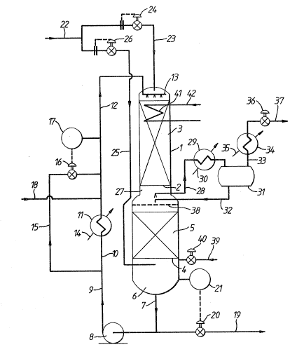
;-, Referring to Figure l of the drawings, a stainless
, steel reactor l is provided with an upper stainless steel
J grid 2 which supports an upper bed 3 of a granular aldehyde
~-~ hydrogenation catalyst. This catalyst is a prereduced
nickel on alumina catalyst in the form of 1/16 inch (1.6 mm~
spheres containing 61~ of nickel ( calculated as metal) in
the 50% reduced form and havin~ a surface area of 140 m2/g
;~ as measured by the so-called B~T method.
Reactor l is of enlarcJed diameter at its lower
end. This enlarged diameter lower end is fitted with a
lower stainless steel grid 4 which supports a lower bed 5 of
the same nickel catalyst. Thermocouples (not shown) are
buried in catalyst beds 3 and 5 and reactor l is thermally
~ . . .
~ ~ . ...
` 1328117
~ 32 -
insulated. Steam heating coils ~not shown) are provided
under the thermal insulation in order to assist in heating
reactor 1 at start up.
Layers of open-celled honeycomb grid material (not
shown) may be laid one on top of one another on top of grids
2 and 4 as the respective bed is loaded up with catalyst,
each layer being offset from the layer below it so as to
assist in even distribution of liquid over the entire bed
and to avoid "channelling" of gas through the bed.
The space 6 below lower grid 4 is used to collect
liquid emerging from the bottom of second bed 5. Such
liquid is withdrawn by way of line 7 and is recycled by
means of pump 8 and lines 9 and 10 through heat exchanger 11
and then through line 12 to a static liquid distributor 13
positioned above upper bed 3 at the top of reactor 1.
Reference numeral 14 indicates a feed line for
heat exchanger 11 for supply of a heating medium ~e.g.
steam~ or cooling water as need arises. ~eat exchanger 11
can be bypassed by means of by pass line 15, flow through
which is controlled by means of a valve 16 coupled to a
temperature controller 17 which monitors the temperature in
line 12. Aldehyde to be hydrogenated is supplied in line 18
and admixed with the liquid exiting heat exchanger 11. The
resulting feed solution which typically contains about 10%
w/w aldehyde is passed by way of line 12 to the top of
catalyst bed 3 at a flow rate corresponding to a superficial
liquid velocity down through the catalyst bed 3 of from
about 1.5 cm/sec to about 3 cm/sec. A liquid intermediate
reaction produck containing typically less than about 1000
ppm aldehyde emerges from the bottom of bed 3 at
substantially the same rate as the flow rate in line 12 and
passes down through catalyst bed 5. Because catalyst bed 5
is of larger diameter than bed 3 the superficial liquid
velocity through bed 5 is less than that through bed 3 t
typically from about 0.25 cm/sec to about 1.0 cm/sec.
:
: ,:
. .. .
1328~7
- 33 -
Alcohol hydrogenation product is withdrawn by way of line 19
under the control of valve 20 which is itself controlled by
means of a level controller 21 arranged to monitor the
liquid level in bottom space 6 of reactor 1.
Hydrogen-containing gas from a pressure swing
adsorption unit (not shown) is supplied to reactor 1 in line
22. A major part of the gas flows in line 23 to the top of
reactor 1 under the control of a flow controller 24 whilst
the remainder is fed by way of line 25 under the control of
a further flow controller 26 to an upper part of the bottom
space 6 at a point above the liquid level in bottom space 6.
Flow controllers 24 and 2~ are set so that the gas flow rate
downwards through catalyst bed 3 at its upper face
corresponds to a flow of hydrogen that is about 105% of the
stoichiometric quantity of hydrogen required to hydrogenate
to alcohol all the aldehyde supplied in line 18. Typically
this corresponds to a superficial gas velocity at the upper
surface of bed 3 in the range of from about 1 cm/sec to
about 4 cm/sec. A minor amount only of gas flows in line
25, typically ranging from about 1% to about 53 of the flow
rate in line 23.
A gas purge stream is taken from the space 27
between the two catalyst beds 3 and 5 in line 28. This is
passed through a condenser 29 supplied with cooling water in
line 30. Condensate is collected in drum 31 and is returned
to reactor 1 in line 32. The resulting purge gas stream is
taken in line 33 and passed through a further condenser 34
which is supplied with refrigerant in line 35. Pressure
control valve 36 is used to control the pressure within the
apparatus and hence the rate of withdrawal of purge gas in
line 37.
Reference numeral 38 indicates a static liquid
distribu~or for distributing evenly across the top of lower
bed 5 liquid that exits upper bed 3. Line 39 and valve 40
are used for initial charging of the reactor 1 with liquid.
: , . . .
~ , ' ~ , . ,
.: . , .
~32~7
~ 34 -
Reference numeral 41 indicates an optional
internal cooling coil which is supplied with cooling water
in line 42.
The use of honeycomb grid material in bed 5 which
has been mentioned above is desirable as an upward flow of
hydrogen containing gas is contacting a downflowing liquid;
in this case there is a distinct tendency, in the absence of
such honeycomb grid material, for the gas to flow up the
cen~ral axis of the bed and for the liquid to flow down the
walls~ The use of honeycomb grid material or of a similar
liquid flow distribution material within catalyst bed 5
helps to obviate this tendency and to promote proper
countercurrent flow through bed 5.
The plant of Figure 2 is generally similar to that
of Figure 1 and like reference numerals have been used
therein to indicate like features.
Instead of a single reactor vessel 1 the plant of
Figure 2 has two separa~e reactors 43, 44 each containing a
respective catalyst bed 3, 5. Reactor 44 is of larger
diameter than reactor 43. Liquid intermediate reaction
product emerging from the bottom of first catalyst bed 3
collects in the bottom of reactor 43 and passes by way of
line 45 to the top of reactor 44. Purge gas is taken from
reactor 43 in line 46 and from reactor 44 in line 47 which
joins line 46 to form line 48 which leads in turn to
condenser 29~ Condensate is returned via line 32 from drum
31 to the top of reactor 44.
The apparatus of Figure 2 permits operation of the
two reactors 43 and 44 at different pressures; in this case
a valve (not shown) can be provided in one or both of lines
46 and 47 and a pump (not shown) can be provided, if
necessary, in line 32.
Referring to Figure 3 of the drawings, a first
reactor 51 is provided with an upper grid 52 which supports
an upper bed 53 of a granular aldehyde hydrogenation
.
132~1~7
~ 35 -
catalyst. This catalyst is a prereduced nickel on alumina
catalyst in the form of 1/16 inch ~1.6 mm) ~pheres
containing 61% of nickel (calculated as metal) in the 50
reduced form and having a surface area of 140 m2/g as
measured by the co-called BET method.
First reactor 51 is also fitted with a lower grid
54 which supports a lower bed 55 of the same nickel
catalyst. Thermocouples (not shown) are buried in catalyst
beds 53 and 55 and reactor 51 is thermally insulated. Steam
heating coils (not shown) are provided under the thermal
insulation in order to assist in heating reactor 51 at start
.~ up.
.,
As in the case of the plant of Figure 1, layers of
~; honeycomb grid material can optionally be introduced into
each bed of catalyst as beds 53 and 55 are loaded into the
reactor 51 in order to assist in promoting even distribution
of liquid throughout the respective bed in operation of the
plant.
,,,
, The space 56 below lower grid 54 is used to
collect liquid emerying from the bottom of second bed 55.
~`~ Such liquid is withdrawn by way of line 57 and is recycled
by means of pump 58 and line 59 through heat exchanger 60.
l It is then fed through line 61 to a second heat exchanger 62
;, from which it is fed by way of lines 63, 64 to a static
,~
liquid distributor 65 positioned above upper bed 53 at the
top of first reactor 51.
Reference numeral 66 indicates a feed line for
heat exchanger 11 for supply of a heating medium (e.g.
steam) or cooling water as need arises. Heat exchanger 62
is provided with a steam heating line 67. Aldehyde to be
hydrogenated is supplied in line 68 and admixed with the
liquid exiting heat exchanger 62. This is mainly product
alcohol, but still contains a minor amount o~ hydrogenatable
material. It acts as a diluent for the aldehyde. The rate
of recycle in line 64 is selected so as to produce, upon
` .
.
,~ ' ~ ' ' '
- ` " ` . . '
.; , . ~
1328117
- 36 -
admixture with the incoming aldehyde in line 68, a solution
of aldehyde in the product alcohol which typically lies in
the range of from about 5 mole % up to about 30 mole % and
is selected such that the superficial liquid velocity down
through catalyst beds 53 and 55 is in the range of from
about 1.5 cm/sec to about 3 cm/sec.
: Part of the recycle stream in line 63 is withdrawn
by way of line 69 and is passed by way of line 70 to a
static liquid distributor 71 fitted near the top of a second
reactor 72.
:,
Hydrogen-containing gas is supplied to first
reactor 51 in line 73. The source of such hydrogen-
containing gas will be described further below.
A gas purge stream is taken from the space 56
below catalyst bed 55 in line 74. This is passed through a
condenser 75 supplied with cooling water in line 76.
Condensate is collected in gas-liquid separator 77 and is
returned to line 57 in line 78. Reference numeral 79
indicates a mist eliminator pad~ The resulting purge gas
stream is taken in line 80 and is passed through a vent
valve Rl which is used to control the pressure within the
apparatus and hence the rate of discharge of purge gas in
line 82.
Second reactor 72 is provided with an upper grid
83 which supports an upper bed 84 of hydrogenation catalyst
and with a lower grid 85 which supports a lower bed 86 of
the same catalyst. The catalyst of beds 84 and 86 may be
the same as that of beds 53 and 55. Layers of honeycomb
grid material may optionally be included in beds 84 and 86
to assist in obtaining even liquid distribution
therethrough~
Make up hydrogen-containing feed gas is supplied
to the plant in line 87 from a pressure swing adsorption
unit (not shown), is compressed (if necessary) by means of
gas compressor 88 and is then passed by way of heat
~ '
13~8117
- 37 -
exchanger 89 and line 90 to the upper end of second reactor
72. Reference numeral 91 indicates a steam heating line.
The gas from line 90 and the feed in line 70 flow in co-
current downwardly through second reactor 72. The rate of
supply of make up gas is controlled so as to correspond to
about 105% of the stoichiometric quantity of hydrogen
required to hydrogenate to product alcohol all of the
aldehyde supplied in line 68 after allowance is made for
dissolved hydrogen leaving the system in the product stream
in line 96. This generally corresponds to a superficial
velocity of gas entering the top of catalyst bed 84 in the
range of from about 1 cm/sec to about 4 cm/sec. As the feed
solution supplied in line 70 to second reactor 72 contains
only traces of hydrogenatable organic material, very little
hydrogen reacts in passage through beds 84 and 86.
Substantially all of any hydrogenatable material remaining
in the liquid in line 69 is hydrogenated in passage through
second reactor 72~ Hence what collects in the space 93 at
the bottom of second reactor 72 below catalyst bed 86 is a
mixture of hydrogen-containing gas and product alcohol.
This is led in line 94 to a product recovery drum 95;
hydrogen-containing gas therefrom is led by way of line 73
to the upper end of first reactor 51, as explained
hereinabove. The gas flows into the top of catalyst bed 53
at a superficial velocity of from about 1 cm/sec to about 4
cm/sec. Liquid product alcohol which collects in drum 95 is
recovered in line 96 and passed on for product purification
in conventional manner~ e.g. distillation in one or more
fractional distillation stages.
Second reactor 72 can be operated, as described
above, on a once-through basis as a single pass reactor.
Alternativ~ly the incoming intermediate reaction product in
line 69 can be admixed with recycled product from product
recovery drum 95. To this end a bypass line 97 is provided
to enable recycle to be effected by means of recycle pump
:
~:
. : :
. ,
132~ 17
- 38 -
98. This pumps crude liquid alcohol product by way of line99 through heat exchanger 150 and then via line 151 to a
further heat exchanger 152 for recycle in line 153 and
admixture with intermediate reaction product in line 69.
Reference numerals 154 and 155 indicate heating or cooling
lines for heat exchangers 150 and 152 respectively, by means
of which temperature control of the liquid supplied in line
70 can be controlled.
Pump 93 and heat exchangers 150 and 152 can be
used at start up of the plant to warm up the catalyst beds
84 and 86 by circulating alcohol through reactor 72 prior to
introduction of aldehyde to the plant. Heat exchangers 60
and 62 and pump 58 can be used in a similar way to circulate
alcohol through reactor 51 and warm its catalyst beds 53 and ~.
55 to the desired starting temperatureO
Product alcohol can be supplied to reactor 51 from
product recovery drum 95t using pump 98, by way of line 156
under the control of valve 157.
If desired, a secondary feed of aldehyde can be
supplied by way of line 158, e.g. at start up of the plant.
The apparatus of Figure 3 permits operation of the
reactor 51 at a different lower pressure than reactor 72; in
this case a pressure let down valve ~not shown) can be
provided in line 73 and a pump (not shown) can be provided
in line 69. Alternatively reactor 72 can be operated at a
lower pressure than reactor 51; in this case a compressor
(not shown) is provided in line 73 and a valve (also not
.~ .
shown) in line 69.
Instead of two reactor vessels 51 and 72 the plant
of Figure 4 has a single reactor 101 containing two
!'~ hydrogenation catalyst beds 102 and 103. As with the plant
; of Figure 3 each bed may optionally include layers of
` honeycomb grid material to assist in promoting even
distribution of liquid throughout the bed and to avoid
~ "channelling" of gas through the bed. Catalyst bed 102
"`,
. `
:
132~7
- ~ 39 -
constitutes a first hydrogenation zone and catalyst bed 103
a second hydrogenation zone. Aldehyde to be hydrogenated is
supplied in line 104 and hydrogen-containing feed gas is
supplied from a pressure swing adsorption unit (not shown)
in line 105 in an amount corresponding to about 105~ of the
stoichiometric quantity of hydrogen required to hydrogenate
all of the aldehyde supplied in line 104 to product alcohol.
The aldehyde feed flows from line 104 in line 106
and is admixed with a recycled alcohol stream in line 107.
The admixed stream, containing typically from about 5 mole
to about 30 mole ~ aldehyde in a predominantly alcohol
diluent, is fed in line 108 to a static liquid distributor
109 above catalyst bed 102. The flow rate is sufficient to
correspond to a superficial liquid velocity down catalyst
bed 102 of from about 1.5 cm/sec to about 3 cm/sec.
Intermediate reaction product is collected at the bottom of
reactor 101 and is pumped by way of line 110, pump 111 and
line 112 to a heat exchanger 113. Then the liquid
intermediate reaction product, which contains typically from
about Ool mole % to about 5 mole ~ chemically unsaturated
hydrogenatable organic material, is fed in line 114 to a
further heat exchanger 115. Reference numeral 116 and 117
indicate respective heating or cooling lines for heat
exchangers 113 and 115. The liquid intermediate reaction
product in line 118 is fed in part in line 107 as the
recycle stream to catalyst bed 102 and in part via lines 113
and 120 to a further static li~uid distributor 121 fitted
above cataly~t bed 103. Again, the superficial liquid
velocity of the liquid flowing into catalyst bed 103 is from
about 1.5 cm/sec to about 3 cm/sec.
The chemically unsaturated hydrogenatable organic
material remaining in the intermediate reaction product is
substantially all hydrogenated to product alcohol in passage
through catalyst bed 103. Substantially pure alcohol is
recovered in line 122 from chimney tray 123 and is pumped by
... .
~32~1~7
- 40 -
means of pump 124 and lines 125 and 126 to a conventional
alcohol purification section ~not shown). If desired, part
of the product alcohol can be passed by way of line 127
through heat exchangers 128 and 129, whose heating or
cooling lines are indicated at 130 and 131 respectively, to
line 132 for recycle to liquid distributor 121.
The hydrogen-containing feed gas in line 105 is
compressed as necessary by means of gas compressor 133,
heated in heat exchanger 134, whose steam heating line is
indicated at 135, and supplied in line 136 to th~ top of
reactor 101 above catalyst bed 103 at a rate corresponding
to a superficial gas velocity at the upper surface of
catalyst bed 103 of from about 1 cm/sec to about 4 cm/sec.
Gas emerging from the bottom of catalyst bed 103 passes
through an orifice 137 in chimney tray 123 and into catalyst
bed 102~ As very little hydrogen is consumed in passage
through bed 103 the superficial gas velocity at the upper
surface of catalyst bed 102 is similarly in the range of
from about 1 cm/sec to about 4 cm/sec. A purge gas stream
is taken from the bottom of reactor 101 below catalyst bed
102 in line 138 and is passed through a condenser 139 which
is supplied with cooling water in line 140. The cooled gas
is passed in line 141 to a gas-liquid separator 142 which is
fitted with a spray eliminator pad 143. The purge gas
passes out in line 144 through control valve 145 to a vent
line 146. The condensate is returned from gas-liquid
separator 142 to rea~tor 101 in line 147. Reference
numerals 148 and 149 represent a bypass line and bypass
valve respectively for use at start up of the plant.
Typical opera~ing conditions in the plants of
Figures 1 to 4 include use of an inlet temperature to each
catalyst bed in the range of from about 100C to about 130C
and a pressure of from about 5 bar to about 50 bar. In each
case the concentration of aldehyde in the feed solution to
each catalyst bed is such as to produce an adiabatic
t
.
- : , - :
.~ .
. , , ~ :
`
~328~17
- 41 -
temperature rise across each bed of no more than about 20C.
v~ Figure 5 illustrates a modified form of plant in
; which an added diluent is used. This form of plant is
useful, for example, in the case in which the presence of an
added adjuvant is desirable, such as ammonia in the
~ . .
hydrogenation of a nitro compound ~e.g. nitrobenzene).
Material to be hydrogenated, such as nitrobenzene,
is supplied in line 201 to a mixing device 202 to which is
also fed in line 203 a mixture of make up diluent and
` adjuvant, such as a solution of ammonia in ethanol
(containing some water), from line 204 as well as recycled
diluent/adjuvant mixture in line 205. The resulting dilute
nitrobenzene solution is fed to heater 206 in line 207 and
admixed with make up hydrogen in line 208. Reference
numeral 209 indicates a steam heating line for heater 206.
The mixture of hydrogen, nitrobenzene, ammonia and ethanol
flows in line 210 to hydrogenation zone 211. This can be a
single reactor or a pair of reactors as used in the plant of
one of Figures 1 to 4. As with the plants of Figures 1 to 4
layers of open-celled honeycomb material can be incorporated
into the, or into each, catalyst bed of hydrogenation zone
211 in order to promote even co-current flow of li~uid and
gas downward through the bed. The liquid flow rate in line
207 is controlled so as to provide a superficial liquid
velocity down through the or each bed of catalyst of from
about 1.5 cm/sec to about 3 cm/sec, whilst the gas flow rate
in line 208 is adjusted to provide at the operating pressure
and temperature of the plant an amount of hydrogen
equivalent to 115~ of the stoichiometrically required
amount. A mixture of a hydrogen-depleted purge gas and of
an ethanolic aniline solution, which contains ammonia and
water produced by the hydrogenation reaction, is recovered
from the bottom of hydrogenation zone 211 in line 212. This
is fed to a gas liquid separator 213. Gas is purged from
the plant in line 214 under the control of valve 215. A
:, `
.
,
..
1328117
-- 42 --
cooler 216 is supplied with cooling water in line 217 in
order to trap volatile materialsO ~he li~auid phase is led
in line 218 to a distillation column 219 from which a
mixture of ammonia, water and ethanol is recovered overhead
in line 220 and is condensed by means of condenser 221. The
resulting condensate collects in drum 222; part is returned
to column 213 in line 223 as a reflux stream whilst the rest
is recycled in line 224 by means of pump 225 to form the
recycle stream in line 205. Reference numeral 226 indicates
a gas vent line to condensate drum 222~ whilst reference
numeral 227 indicates the cooling water supply line for
condenser 221. The bottom product from column 219 in line
228 consists of substantially nitrobenzene-free aniline
containing a minor amount of ethanol and water produced in
the reaction. Part is recycled to column 219 by way of line
229 and column reboiler 230 whose steam supply line is
indicated at 231. The remainder is passed on for further
purification and storage in line 232.
In a variant of the plant of Figure 5 mixing
device 202 is omitted and lines 201 and 204 are connected to
line 224 upstream from pump 225 which then serves as a
mixing device.
The invention is further illustrated with
reference to the following Examples. Examples 7 and 9 are
Comparative Examples and do not illustrate the invention.
Examples 1 to 11
The hydrogenation of a C13 aldehyde stream
containing 69O98 wt96 n-tridecanal, 5.70 wt % 2-
methyldodecanal, 0.30 wt % of heavy by-products resulting
from aldehyde self condensation reactions and the balance
C12 aliphatic hydrocarbons, was studied in the apparatus
depicted in Figure 6. This included a reactor 301 made of
stainless steel tubing, 2~54 cm internal diameter and 91.4
cm in length, arranged with its axis vertical and fitted
with an annular jacket 302 through which hot oil from a
.,
.,
. . -
.. . .
.
~ . ~
,, .
- :
~328~17
..
~ 43 -
thermostatically controlled bath could be circulated.
Reactor 301 contained a bed 303 of catalyst supported on a
layer 304 of 1.6 mm diameter glass beads 2 cm deep which was
itself supported on a stainless steel mesh grid 305 some 10
cm above the base of reactor 301. The volume of catalyst
bed 303 was 52.3 ml and the catalyst was a pre-reduced and
air stabilised nickel on alumina catalyst containing 61% w/w
of nickel (calculated as metal) in the 50~ reduced form and
having a surface area of 140 m2/g as measured by the so-
called BET method. The physical form of the catalyst was
near spherical granules of a nominal 1/16 inch (1.6 mm)
diameter; the actual size range limits of the particles was
from 1.4 mm to 2.36 mm as determined by sieve analysisl The
upper portion of reactor 301 was filled with a layer 306 of
1.6 mm diameter glass beads; this layer 306 ensured that the
temperature of the feed solution and entrained hydrogen
supplied to catalyst bed 303 could be controlled to a
preselected value.
Reactor 301 was also fitted with a thermocouple
pocket 307 of small diameter for a thermocouple 308. During
the packing procedure it was determined that the depth of
catalyst bed 303 was 10.5 cm. Liquid could be withdrawn
from the bottom of reactor 301 in line 309 by means of pump
310 and recycled to the top of reactor 301 in line 311. The
rate of recycle of liquid in line 311 could be measured
using a mass flow meter (not shown). Aldehyde feed could be
supplied to the apparatus from a burette (not shown) in line
312 by means of a feed pump (not shown). ~ydrogen could be
supplied from a storage cylinder via a pressure let down
valve and a flow controller (neither of which is shown) in
line 313. A mixture of gas and liquid could also be
withdrawn from reactor 301 by means of an overflow pipe 314
and passed in line 315 to a gas/liquid separation vessel
316. Pressure control valve 317 allowed a purge gas stream
to be let down to atmospheric pressure and passed in line
.. . ..
:;: - ~ . . . ..
~328117
~:
- ~4 -
318 to a wet gas meter (not shown) before being vented to
the atmosphere. Liquid product could be removed from the
system in line 319 by means of a pressure let down valve 320
- operating under the influence of a liquid level controller
321. Samples of this liquid product were analysed by gas-
liquid chromatography from time to time. Such analysis was
repeated after any change in operating conditions had been
effected until the results showed that steady state
conditions had been re-established. The whole apparatus was
positioned in a fume cupboard supplied with warm air at 40C
to eliminate any danger of blockage of lines due to
solidification of n-tridecanol (m.p. 32-33C~.
After purging the apparatus with nitrogen
approximately 120 ml of C13 alcohol were charged to the
apparatu~ by means of line 312, the circulating hot oil flow
was established at a temperature of 120C, and pump 310 was
set into operation. This quantity of liquid was sufficient
to fill the bottom of reactor 301. A flow of hydrogen was
established through the apparatus and then the system was
brought up to operating pressure and the aldehyde feed pump
started. The results are listed in Table 1. A11 ~xamples
were carried out using circulating oil at 120C and in each
case, except Example 7 and especially Example 9 when
~hermocouple 308 indicated an incipient temperature runaway,
the temperatuxe of the catalyst bed 303 remained within 5C
of 120C. H2 flow rates are measured in ~normal" litres per
hour ~i.e. litres of gas at 0C and 1 bar).
.
. !
`!
.,
. `~
` ,i
':!
,
.
~;: - - . :- :
.; , . .: . ~.:
.
:: ~328~l~L7
- 45-
¦ b~ 0 _I N ~ 5 a
~ 9
dp a 0~ ¦ O ~ o l l l l
... Ul _ ~ O ~ O N _ _ ~
~ ) ~P -~ ~ ~ ~ _i ~i er ~ ,ta,~j
_ _ _._ __ ___~ _
i L~ I 1 ~ I o l ~
~ N ~ r ¦ u ¦ ¦ _ ¦ ~ ¦ ~ ¦ ~
_ . -_ . ~ ._ _ _ _ ,~
~ 0~ ~ ~ ~ OD u~ ~ a~ G~ C~ ~ '8
3~ ~ ~ ~ ~ ~ ~ ~ ~ ~ ~ ~q
. ... _. _ . __. _ __ _ ~_ ._ _
,.. . ~ .Y
I ~ ~ I I ~1 I W ¦ ~ ¦ ~ ¦ CO ¦ oO, ¦ o
.' ~ I _ ~._
L~ ¦ N ¦ (rl ~
: ~ .
. .
: ~ . . . . . .
~3~81~7
,, `
- 4~ -
~; As the recycle rate in line 311 is known and the
';- n-aldehyde concentration, i.e. C-C~O]e~it, in the li~uid
~ being recycled is also known and as the feed rate and
,. ,
aldehyde concentration in the material supplied in line 312
are also known, it is readily possible to calculate the n-
aldehyde inlet feed concentration, i.e. [-CHO]inlet, for
each Example. From these figures was calculated, in each
case, the mean n-aldehyde concentration, i.e. ~-C~O~mean, in
the reactor, according to the equation:
-CHO ~ me arl a [-CHO]inlet + [~C~]exit
The mean n-aldehyde concentration is tabulated in Table 2
against the percentage change in n-aldehyde concentration
(~[-CHOl} from one end of the reactor to the other. These
data observations are plotted in Figure 7.
,
,~,
:
. ~
:..
: `,
.'~'`,
~`J'
",``1
.' lj
'`1
,
'~
~,` : '' ` ' ' : `'` , `
; ' : `
: ` ' '
:` :
: `~
l 32~117
. .
TABLE 2
. ~
:. . . . _ ,
Example ~ -CHO ~mean ~ t -CHO ] Liquid
No . recyc le rate
(% w/w) ~ w/w~ (l/hr)
_
1 10 .58 0.55 25.8
2 4. 41 0 . 30 25 .8
.__
3 1.94 0.16 25.8
_ 0 . 98 0 . 08 25 . 8
31 .56 0 .71 25 .
':, _ _ .. _
6 30 . 76 0 . 72 25 . 8
,~
7 31.99 1.3~ 13.0
8 33.93 0. 66 25.8
,, ~
9 28.18 3.76 5.1
1~ 1. ~4 0. 16 25.S
'
. . .
:,
.
,
,.
'`
`:~
,.~
. .
. . : ,
.' . ~ ",: ' ~,: `
- :
.
132~7
- 48 -
Examples 1 to 5 and 10 were all carried out with a
liquid recycle rate of 25.8 l/hr and a hydrogen purge rate
of 19.8 1/hr so that these data define the relationship
between the amount of n-aldehyde converted in passage
through reactor 301, i.e. ~[-CHO], and the n~aldehyde
concentration, [-CHO]mean, within the reactor 301 under
these conditions of hydrogen flow and liquid recycle rate.
A considerable reduction in hydrogen purge flow rate to 3.9
l/hr makes very little difference to the amount of n-
aldehyde converted in passage through reactor 301, i.e.
~[-CHO], as can be seen by comparison of Examples 5 and 8.
A large increase in hydrogen purge flow rate to 39.5 l/hr
makes very little difference ~o the amount of n-aldehyde
converted in passage through reactor 301, i~e. Q [-CHO], as
is readily apparent by comparison of Examples 5 and 6. In
contrast a reduction in liquid recycle rate, although
increasing the conversion of n-aldehyde in passage through
reactor 301, i.e.~ l-CHO], as shown by Examples 7 and 9,
caused a marked increase in catalyst bed temperature, as
detected by thermocouple 308, despite the use of circulating
oil at 120UC in jacket 302. This incipient temperature
runaway was further accompanied by an increase in "heavies"
formation.
- The data defining the curve of Figure 7 represent
a scan of different horizontal segments of catalyst in a
large reactor and can be used to calculate the depth of
catalyst bed required for a commercial reactor operating
j under appropriate conditions including aldehyde
concentration~ flow rate and temperature according to the
teachings of the invention.
Comparison of the relative amounts of aldehyde
converted over the xeactor system calculated from the flow
rates and aldehyde concentration changes across the reactor
in Examples 7 and 9, using Example 5 as a reference, shows
that virtually the same amount of aldehyde is converted in
:
~ .....
` ~
~3281~ 7
- 49 -
the reactor system in Example 7 as in Example 5, despite a
significant increase in catalyst temperature and some
increase in heavy by-products production. Comparison of
Examples 5 and 9 show that an increase of only about 12% in
aldehyde conversion by the reactor system has been gained at
the expense of an unacceptable temperature rise and increase
in heavy by-products formation. Example 9 in some measure
represents the situation arising in a "local low flow volume
element" of a large catalyst bed operated at low superficial
liquid velocities. These comparisons illustrate that the
space time productivity of the catalyst is maintained at
high liquid superficial velocities and that potentially
dangerous temperature excursions with conse~uent loss of
catalyst activity and selectivity are obviated using the
~ process of the invention.
! Examples 11 to 36
The apparatus of Figure 6 was charged with 58 ml
of the same catalyst and was used to investigate further the
hydrogenation of the same C13 aldehyde feedstock that was
; used in Examples 1 to 11. The reaction conditions and the
results obtained ar~ summarised in Table 3. In Ex~mples 34
to 36 the C13 aldehyde feedstock was diluted with n-
tetradecane. In each case the liquid recycle rate was
maintained at 28 l/hr, thus ensuring that the superficial
ii, linear liquid velocity through the reactor was at least 1.5
~, cm/sec~
`~ Figure 8 summarises the results of Examples 31 to
' 36. This is a graph of the amount of aldehyde converted per
hour in the apparatus plotted against the concentration of
aldehyde in the liquid phase exiting the reactor. The
numerals on the graph indicate the numbers of the respective
~ Examples. It will be seen that two separate curves can be
`~ plotted, one representing the data obtained when no diluent
(i.e. n-tetradecane) has been added and the other when a
` diluent is used.
,"j
,.
.i
. .
~50 ~3281~7
.. . .. _ ... . _
e ~ ~ ~ r ,1 ~ ~ X ~ N
_ ~
E~ x ~ ~
;, dP ~ 2
~ `D ~ r ,.
~__ , _ _ _ _ _ _
~:~, ~_ l l l l ~ l ~ l l l
X l X I ~ r~ I x
~:: ~ ~ O O O O O O O O O O
. . ~
.. . . . . .
.~. . .. . :
. , ..... , ~ . . ... .
; . , - ~ .
. . . ~ ~ .. -. .: . .
-
.
1328~17
- 51 -
~ C ~ i~ 2 N o
_ _____._____ ~ ___ _
. e _ ~ ~ ~ ~ = ~ ~ u~ N
;~lou- '--- . _ _ _
'~}- O U~ _l ~ U~ ~D U~ ~1 a
~ 1~ ~ ~ ~`J ~ N ~I N ~ ~
IY; E~ -~ ~ ~ r~l _1 _~ _1 _1 ~3 _1
~ i~ - _ _ . _ _ _ _ _
~, 1~3s C~ O Ct~ O C:~ I~ I~ O S` O
'' ~ ~ _1 ,_1 ~I ~1 ~1 ~I
N ~ O ¦ O ¦ _I ¦ O ¦ N
, ~) 1~4-- O O O O O O O O O O
." ~ ~ 3 ~ . . I I
,` O I~;ç45~ _~ t~ -~ ~ ~$ ~ ~ ~ ~
:`~ O _ _ _ _ _
1~ ¦ N ¦ N ¦ ~ ¦ N ¦ t`l ¦ N
''
~ , - , . .~
: ,~ . ' . ' ' ' '.
:~ . :.: `
` `` ~32~17
- 52
N ~ O ~` N C~
..
L~ ~5
~ ~ ~ ¦ ~ ¦ O
O O O O O O
G ¦ N ~ N ¦ N ¦ N
;.'~,'.' - '' ' ' . ~' ~ ' - ' ' .
' ~ '` : ~
. . .
~32~17
- 53 -
Regression analysis of the rate of conversion ~RN)
of n-aldehyde to products (expressed as gm moles of C13
aldehyde converted/litre of catalyst/hr) produced an
equat.ion of the following form.
R = A eE/TK RxBara . %NALDb . ALH2C
%~vyd
where RN = gm moles of n-aldèhyde hydrogenated to
products/litre of catalyst/hr
TK = average catalyst and temperature
RxBar = Reactor pressure tbar)
~NALD = Mean ~ n-aldehyde in reactor ~calculated)
ALH2 = Calculated actual litres/hr of hydrogen
, exiting from the bottom of the catalyst bed
at reactor pressure and temperature
. %HVY = % "heavies" in the reactor exit stream
,I Coefficient Standard Error of Coefficient
- a = 0.156 0.122
. E = -4867.78 255.6
l, b = 0.837 0.0867
c 0.0179 0.111
d = 0.4497 0.0356
A is a constant = 345756
e = the base for natural logarithms ~i.e. 2.7182g...~
The validity of the above rate equation is shown
in Table 4 where predicted rates versus actual rates, in gm
'~ moles/l catalyst/hr, are com~ared.
,",
:, .
.
..
, ,
- - .. - .. , , :
~32~1~7
.
- 54 -
Table 4
Example No. Observed Rate Rate Predicted by Rate
Equation
11 2.99 2.82
12 10.15 9.77
13 10.33 10.12
14 5.~1 5.44
~.80 ` ~`5.86
16 10.71 10.~8
17 10.71 10.34
18 5.80 5.56
19 8.25 8.14
5~61 5.62
21 10.33 10.58
22 ~.25 8.38
23 ~.06 8.02
24 7.87 7.62
8.25 8.28
....
~ 26 3.00 2.95
.:~ 27 ~.00 3.01
28 5.61 5.60
` 29 2.99 2.94
9.77 10.06
~l 31 2.92 3.13
:~ 32 5.54 5.69
' 33 9.81 9.98
~i 34 2.88 2.93
5.35 5.55
:. 3~ 9.2~
This analysis of Examples 11 to 36 shows that:
(a) ~ydrogen flow has little or no positive effect on
:~. the rate of hydrogenation under these liquid flow velocity
~:' conditions;
~b) Reactor pressure ~i.e. hydrogen pressure) has a
minor positive effect on the reaction rate and is of poor
~.
,
- . . .. ,.. . . ~
:.'
~328117
- 55 -
statistical significance (over the pressure range used
18.24 to 25.13 bar); and
(c~ "Heavies" are catalyst inhibitors.
These conclusions substantiate in a more rigorous
way the insensitivity of the reaction kinetics to the rate
of hydrogen passing through the catalyst bed which can be
noted from comparison of Examples 5 and 6 and of Examples 5
and 8. Also the rate equation describes the effect of the
process conditions on the catalyst in a diferential manner;
suitable integration of the equation over the depth of a
commercial catalyst bed will provide a valuable prediction
of the bed's performance.
The plants of Figures 1 to 5 and the operating
techniques described above are generally applicable to
hydrogenation of organic materials. It will accordingly be
readily apparent to the skilled reader that the teachings of
the invention can be practised with a wide variety of
hydrogenation reactions other than the aldehyde
hydrogenation reaction specifically described in relation to
Figures 1 to 4 of the accompanying drawings and the
nitrobenzene hydrogenation reaction described in relation to
Figure 5 of the drawings.
Example 37
Examples 1 to 36 used experimental systems where
reactors of small diameter (2.54 cm) were used. Commercial
reactors of much larger diameter are necessary in order to
achieve the necessary production rates. Therefore the
distribution of gas and liquid passing in co current
downflow through a much laxger bed of particulate solid was
investigated in an apparatus which is illustrated in ~igures
9 and 10. This comprises a rectangular section column 401
which was constructed from 1.25 mm thick "Perspex"
(Registered Trade Mark) sheet so as to enable its contents
to be viewed. Partitions 402 near its base divided the base
of the column 401 into six bays 403~ each of which had a
:"
:`:
- . . .. . .. . .. .. . . .... . . .
~32~117
- 56
corresponding outlet line 404 for water and an outlet line
405 for air. Reference numeral 406 indicates a perforated
support for a bed 407 of particles intended to simulate a
hydrogenation catalyst. Bed 407 consisted of impervious
ceramic balls of nominal size 2.4 to 4 mm, more than 80% of
which were 3 mm or less in diameter. Water was supplied in
line 408 to a bar distributor 409 above the top of the bed
407, whilst air was fed in line 410 from a compressor (not
shown) to inlets 411 at the top of column 401. Bed 407
measured approximately 460 mm x 75 mm x 1425 mm and was
topped with a layer of 12.7 mm diameter polypropylene balls
approximately 200 mm deep which was intended to enhance the
uniformity of distribution of the water over the top of bed
.;
407. The water that was collected in each bay 403 was
conducted along a line 404 of standard length to a
corresponding turbine meter in a bank 412 of turbine meters,
each receiving water from a respective bay 403. Similarly
air from each bay 403 was conducted along a line 405 of
standard length to a corresponding turbine meter in a bank
413 of such turbine meters, each receiving air from a
respective bay 403. As indicated by reference numerals 414
and 415 the signals from the two banks of meters 412 and 413
were transmitted to respective data loggers (not shown). By
providing lines 404 o~ essentially identical length and
diameter for water and lines 40S similarly of essentially
identical length and diameter for the air flow from each bay
403 it was ensured that, so far as possible, the risk of the
air and wa~er flow measurement systems interfering with the
measurements of flow through the bed 407 was avoided.
However, at low air flow rates, of the order 2 to 3 litres
per minute, the air flow measurement turbines of bank 413
became inaccurate and/or inoperative. Accordingly the
corresponding air distribution measurements have no
significance in this low air flow range. From the meters of
bank 412 the water was collected in a tank 414 and
,..
,
` ` 13281~7
- 57 -
recirculated to the top of the apparatus by pump 415.
Measurements were made with water flow rates in
line 408 of 30 to 55 litres per minute and air flow rates in
line 410 of S9 to 5 litres per minute. These flow rates
were chosen to simulate a range of flow rates likely to be
encountered in a commercial hydrogenation reactor operated
in accordance with the teachings of this invention and
correspond to a liyuid phase superficial velocity of 1~43 to
2.63 cm/sec and a gas phase superficial velocity of 0.096 to
2.01 cm/sec.
The distribution of fluid across the bed 407 was
calculated as follows:
For each fluid:
Average flow = sum of flows/6
Variance - [Average flow - measured flow~
Average variance = sum of variances/6
~It should be noted that the variance was always recorded as
a positive number)~
The results are recorded in Tables 5 to 7 and
~j plotted in Figures 11 to 13.
At the higher gas and liquid flow rates the
operation of a highly dispersed gas/liquid regime was
clearly shown.
In those cases where active liquid/air bubble
movement was visually observable no static regions of the
bed were evident; the phase in a given bed void was replaced
by the other phase at apparently random intervals.
From the results obtained it would appear that the
efficiency of phase distribution (as measured by the
` variance from average flow per port) is a function of
throughput. That is, higher air/water flows (and hence a
steeper pressure gradient) lead to a better gas/liquid
distribution. This observed effect is undoubtedly enhanced
by the poorer accuracy of the measuring devices at low flow
rates and also by the increasing effect of any fortuitous
:.
- ~ , ,. : , :
... . . .
~, :
~L32~1~7
~ 58 -
physical variations between the 5iX gas/liquid collection
and separation ports. It is therefore highly probable that
the actual distribution is always better than the observed
distribution. It should also be noted that the corners of
the rig of Figures 9 and 10 provide a low resistance fluid
path to the left-hand and right-hand bays 403 5as
illustrated) for geometrical reasons; this effect will also
add to the variance observed. A circular cross section
catalyst bed will give better gas/liquid distributions than
those observed with a rectangular cross section bed.
These gas/liquid distribution studies show that
effective gas and liquid co-current downflow hydrogenation
reactions can be achieved without using large excesses of
hydrogen containing gases.
Table 5
Water flow in 30-36 litre/min range
;~ Air Air Water
l/min % av. variance % av. variance
i 9.8 42.9 6.8
10.9 19.3 3.g
14.8 24.~ 6.5
19.7 21.9 5
2g.~ 15.6 3.6
39.1 14.2 10.4
42.4 4.2 4.4
49~5 12.7 9.3
. . .
.
.
.. ~ .
' ~ ' ' - '
.
,:
~32~ ~7
- 59
Ta~le 6
Water flow in 44-46 litre/min range
Air Air Water
l/min % av. variance % av. variance
9.3 34.8 5.3
36.6 4.2
~ 19.2 20.8 5.9
:' 20.2 16.8
: 28 4 5 1~ 6
`I 30 11.7 4.4
37.9 11.8 5.2
4~ 10.2 3.9
` 44.9 12.3 4.5
47.7 9.2 4.2
~`. 48.4 9.1 3,1
:. 'able 7
Water flow in 53-56 litres/min range
: 1 Air Air Water
., l/min %av4 variance ~ av~ variance
"1 11.4 21.1 5.6
:~' 13.1 23.4 6.5
20.2 1305 5.2
33~1 8.9 2.9
33.3 8.4 5.4
~, 43 5.6 3-4
:~ 43.3 5.8 3.3
~ 43.7 7.5 4.4
`~ 50.3 3.8 3.6
:~ 59.8 7.6 3.6
.,
" ~ ,
.,
:.
;~ -.
''~ ' ' `' `'1 ~ ' . ,: