Note: Descriptions are shown in the official language in which they were submitted.
~3~27
PROCESS OF AUTOMATIC SEQUENTIAL PRODUCTION OF POT~NTIOMETERS
AND POTENTIOMETER 03TAINED THEREOF.
.
~ACKGRO~ND OF THE INVEN~ION
'
D~ ib~
This invention relates to a process of automatic
sequential production of potentiometers, and potentiometer
obtained thereof, wich i5 of the type constituted by a
flattened glass-shaped casing, on the bottom of which is
located a laminate electrical resistance element, of an
incomplete annular shape whose ends remain connected to
terminals, such casing lodging as well a slider, in permanent
mechanical and electrical contact, with mentioned resistance
and with a collector terminal, which is joined wi~h the
mouthpiece of the casing it closes, said slider being in
turn assembled on a slider-holder rotatably lodged in a
central passageway o tne casing and with a slot or suitable
configuration to enable easy operation from outside.
This process consists of an automatic ass~mbly
operation of the component elements, obtained in prior or
independent operations, some of them, such as the terminals,
slider and collector, configured on a metallic band, diecut,
with holes on its sides to make possible ~ts step-by-step
traction by a transfer unit, producing during such advance~
ment the incorporation of the different elements, in such a
way that the assembly gradually advances in the orm of a
continuous band until the final stage of mechanical and
~'~
.
-:
~ ' .
32~1~7
-- 2
electrical checking of each potentiometer is completed, from
which moment they are taken part in independent units.
The process is characterized in that it comprises
following basic stages: ,
a) formation of a subassembly including the insulating
casing, electrical resistance track and terminals, in the
form of a continuous band, in which the terminals are initia-
lly defined by dieing.
b) configuration of a subassembly including the slider-hol-
der, slider and collector.
c) junction of bo~h subassemblies.
d) mechanical and electrical checking of each potentiometer.
e) selective storage if finished units, carrying out stages
a) and b) from laminar 01ements in the form of a supporting
continuous band, diecut, which are linearily guided and
hauled, in step-by-step advancement, aided by holes on their
two sides this laminar elements either bearing or having
sequentially associated the different components, convenient-
ly oriented, to form each of the sub-assemblies. On the
other, the two sub-assemblies resul~ing from stages a) and
b) are interlocked at stage c), also gradually advancing in
the form of a continuous band, until completing stage d),
after which and once each assembly is completed, they are
divided into independent units and proceeding to the execu-
tion of stage e).
Description of the Prior Art
As antecedents of the invention, we can note the
Spanish patent of invention n 537.848, and the German
patent n 1.176.241, both concerning a production process of
potentiometer in which it is started from a laminar metallic
band, previously diecut, with its conformation of some of
the integrant elements, basically the collector and the
terminals, performing during the gradual advancement o such
band, the incorporation of the rest of the component elements
although with characteristics completely differen~ from the
object of the invention.
13~8127
Concerning the attachment of the resistant track
to the terminals, we can mention the following processes and
patents related to:
. rivet-attached: USA Pat. n 2,160,142
. cramping and riveting: USA Pat. nQ 2,736,783
. stapling: USA Pat. n 4,482,883
. cements or cermet pastes: SPANISH Pat. n 466,765
. welding: USA Pat. n 3,354,418
. moulding: BRITISH Pat. nQ 689,001
Briaf Summarv of the Invention
f _ _
The process concerned in this invention is charac-
terized so as to carry out the first of the stages a),
starting from a continuous laminar band, in good electricity
conductor material, in which by a diecut operation, two rows
of parallel terminals are configured, perpendicular to the
developpment of such land direction joined by cross strips,
in such a way that they remain directly facing each other
and lengthwise shifted, staxting from alternate sides of the
band. Such band presents holes on its side bands, also
lengthwise by-passed, to enable an easy pulling of same by a
transfer equipment. The procedure, in a first stage, is
characteri~ed in that it divides lengthwise said band into
two pieces, mutually backing later on the two halves in an
appropriate orientation, with correspond nce of the holes of
the side bands and by-passing of the terminals, which implies
an utmost profit of the material used for the terminals,
minimizing the waste scraps.
It is also characteris~ic of this process the way
of attachment between the terminals and said insulating
casing, which is performed by a particular stapling of such
elements on the bottom of the casing, executed by the folding
of two appendages that end said terminals.
The aim of this process is also to transfer the
slider and slider-holder on the collecting terminals band,
as well as the methodology used to couple one of the bands,
~3~127
-- 4
that bears the subassemblies of stages a) and b) to the
other.
Brief Description o-E the Drawings
The invention will now be described in detail with
reference to the accompanying drawings wherein:
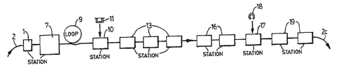
Figure 1 corresponds to an outline in blocks,
representative of stage a) of the process.
Figure 2 also shows by means of a layout in blocks,
the rest of the process, the first part of the left, near
the rotary station represen~ed by a circle with an arrow
corresponding to stage b) of the process.
Figure 3 shows a ground plan of a sector of the
conveyor ~and of the terminals after the first diecut opera-
tion that configures said elements according to two rows of
parallel, alternate, by passed elements.
Figure 4 corresponds to a detailed view, in ground
plan, of the elbowing of the appendages that ends the termi-
nals, forming an U-shaped fork configuration as it emphasized
in figure 5.
Figure 6 shows the band division in two parts of
the band drawn in figures 3, 4 and 5, with arrangement of
one of the half-parts on the other band, by tilting of its
plane by means of a loop, superimposing the two bands with
corxespondence of the holes of its sides and lengthwise
by passing of its terminals.
Figure 7 shows the detail of arrangement on the
double terminal band, after the operation of figure 6, of
the insulating casing assembly.
Figures 8 to 11 draw with full details the opera-
tions to achieve the linkage between the terminals and the
ends of the resistance element, this latter remaining dispo-
sed on the bottom of the casing, by means of a stapling of
particular characteristics, as it will be detailed.
,
. ~ . '
'' . ,
~328~27
- s - -
Figure 12 shows a band holding sliders, figure 13
showing a detail of the curving of the part designed to be
supported on the resistance element/ of such sliders.
Figure 14 shows represented in ground plan a
sector of a band holding collector terminals.
Figure 15 shows the same band of collector termi-
nals of figure 24, after insertion of slider-holder and
slider;
Figures 16 and 17 show different conformations of
the collector terminals, that wiIl be depending on the
assembly position of the potentiometer.
Fïgure 18, is shown the complete assembly of the
potentiometer still incorporated at the terminals band
corresponding to stage d), above referred from which moment
and once the chscking stage is completed, it is proceeded to
taKe each potentiometer apar~ by cutting said band, which,
later on, is cut into pieces to simplify wastes storage.
Figure 19 show the potentiometer obtained.
Detailed Description
. _ .
As ik was stated and which particular reference to
the two firs~ igures, the process proposed comprises a
station -1-, where a laminar band or ribbon -2-, of a good
electricity conductor material is oiled previously diecut,
presenting a structure as the one shown in figure 3, and
comprising terminals rows -3-, parallel, joined by cross
strips -4-, whose terminals -3-, starts from alternate sides
of the band -2-, where there exists holes -5-, lengthwise
by-passed. The terminals -3-, end in curvilinear appendages
-6-.
Said band -2-, holding the terminals -3-, is
subjected in a first operation, by means of~statlon -7-, to
a preforming of appendages -6-, to elbow them, fork-shaped
-8-, as it can be seen in figure 5.
Next, band -2-, is divided into two parts by a
lengthwise central plane, one of the halfparts -2a-, advan-
, . ,, , . -
- 6 - ~32812~
cing gradually lengthwise, while the second -2b-, is looped
-9-, (see figure 6) and titled, being afterwards arranged
superimposed on the other halfband -2a-, with exact corres-
pondence between the holes 5, o its side bands and corres-
ponding lengthwise separation of the terminals therefore
obtaining a double band of terminals we shall later on
marked with numeral -2c-.
Subsequently at station -10-, it is proceeded to
the arrangement of the casing -11-, associated to the termi-
nals band -2c-,` inserting the appendages -6-, fork-shaped
-8-j through radial holes -12- (see figures 8 to 11) worked
on the bottom of such casing -11-, according to detail in
figure 7.
Next, it is proceeded to perform by means of
stations -13-, the folding of first appendages or lugs -6-,
against ~he bottom of the box, whose task is carried out by
means of a two-stage folding, as figures 8 and 9 show in
full detail. In the first of such figures there can be seen
that by means of a first tightening tool -14-, an angular
folding is produced of one of the appendages -6-. Next a
second pressing tool -15-, acts on the medium area of the
appendage -6-, previously folded in angle, ~olding it against
the bottom of the casing -11-, at 90 degrees. Thus a termi-
nal portion -6a-, of the appendage -6-, remains slightly
raised.
Continuing on the assembly line referred in figure
1, we find the stations -16 , where an engraving is achieved
according to a conventional technique of graphic characters
on the external face of the casing of the potentiometer,
such as codes of series, type, etcO
Later on, at station -17-, the resistance is
introduced inside the casing -11-, for which purpose the
resistance element -18-, possesses a protrusion that assists
in its driving and pre-positioning as much with r~gard to a
feeding guide channel, as with regard to the casing -11-,
where there exists a recess on the cylindric wall delimiting
the seat of such resistance element -18-.
,
.~ - ,. ..
'` ' ' ` '" ' ' '` - ~
.
`'- ' : ' '' ~ ,;'
- ' ~' . . ' ~ . .
_ 7 _ ~328127
Next, at stations -19-, it is proceeded to the
final stapling of the resistance elements ends by folding
second appendages -6-, that ends the terminals -3-, such
operation producing likewise two stages and using tightening
tools -20-, and -21-, as it is shown in figures 10 and 11,
respectively.
Observing figure 11, it is shown in same that the
resistance element -18 , remains tightly held colleted
between the ends -6a- and -6b-, of the appendages -6-, of
the terminals -3-, the first of such appendages 6a-,
offering because of its particular folding configuration, an
elastic reaction that increases the stability of the mechani-
cal link.
For t.he forming of stage b) subassembly, it is
started from a band -22-, that bears a first diecut at the
station -23-, for a complete configuration :OL the sliders
-24-, according to detail in figure 12 whose elements -Z4-,
already present at the moment of entering the station -23-,
a folding o portion -24a-, designed to contact the resistan-
ce element -18-.
:Such sliders band -22- enters next in a tangential
orientation to a rotary transfer station -25-,where also
goes by means of feeding units -26-, the slider-holders
- -27-, that are insarted in the sliders -24-, from which
moment the slider-holder subassemblies -26-, and slider
-24-, go apart, unit by unit, and are transfered by means of
a rotatory unit -25-, on a band -28-, of collectors -29-,
previously diecut in a station -41-, and oiled at unit -42-,
constituting a composite assembly, in the form of a band as
shown in figure 15.
Next, said band -28-, integrating in it the
subassembly of stage b) linearily advances toward an assem-
bling station -30-, where its coupled with~ the band -2c~,
occurs, integrating on it the subassembly of stage a).
Afterward, at sta~ion -31-, the coupling is achie-
ved by thermal stapling of perimetral areas of the casing
.
.. ,. ~
. , . .. . .:,.: ' ' . .
-
.
'
~328127
-- 8 --
mouthpiece on the periphery of the collector, and at station
-32-, by some dies that eliminate the terminals ends, remo-
ving the double band -2c~, the potenciometers remaining only
joined through the collectors band -28-.
After that, at station -33-, microprocessor-controlled, a
unit by unit checking, of the electrical characteristics of
the potentiometers is achieved, still keeping its band
organization.
Later on at stations -34-, diecut and conforming
operations of the potentiometer terminals are performed
according to the characteristics of assembly desired (Verti-
cal or horizontal), two possible arrangements for a collector
-29-, having being represented on figures 16~and 17.
Next at stations -35-, the potentiometers that
duly passed the checking stage are taken apart and at the
following unit -36-,:the ones detected as incorrect are
collected, eliminating them in both cases from the band
-28-, which goes on gradually advancing and that is finally
cut into pieces at stations -37-, to simplify storage tasks
of waste materials.
Though it was not expressly detailed, all the
bands considered possess holes that were indicated with
numerals -5-, for band -2-, -38-, for band -22-, and -39-,
for band -28-o
' Also after the rotary station -25-, the band -22-,
is collected at station -40-, where as it occurs with band
-28- ~ it will result advantageously cut into pieces.
Concerning the potentiometer obtained in accordance'
with the invention, it comprises a casing -11-, in an insula-
ting material internally lodging an annular electricàl
resistance element -18~, with a protuberance -43-, the ends
of said resistant element being connected to pairs of appen-
dages -6-, of contact terminals -3-, by a bent of said
appendages which enter into said casing -11-, through pairs
of grooved passageways -49-, remaining the end of the appen-
dages -6-, resting under the resistant element -18-, slightly
rais-d and the secon~ appendages folded at 90 degrees over
-
- ~ , - .
,' -~
'
: `
~328~27
the ends of the resistant element. Said casing also houses a
slider holder -27-, with some protuberances -45-, -46-, on
its side wall as generatrix ribs, symetrically distributed,
that provide a friction with the walls of the guiding hole
-50-, of the casing -11-, and with the edge of a central
opening of the collector plate -29-. The collector terminal
-29-, has an annular projection -48-, over which rests the
periphery of the slider holder 1 5 head, thermally-deformated,
thus axially fixing said collector -23-, to said holder
-27-j which in turn is fixed to the casing -11-, by deforma-
tion over the collector of said casing -11-.
: