Note: Descriptions are shown in the official language in which they were submitted.
`~ 13~2~
., .
.' 1
.'
,
` This invention relates to beverage dispensing
apparatus and is particularly concerned with such
. .,
apparatus which may be used in the home for rnaking
~, carbonated drinks.
There have recently been a number of proposals for
home carbonation apparatus which is provided with a
carbonation means for carbonating water and a flavoured
concentrate supply means arranged so that the
concentrate is mixed with the carbonated water after
:.,
discharge o~ the latter from the carbonation chamber.
~, The concentrate may be contained in replaceable bottles
¦ and it has been proposed that the bottles be
I pressurized with carbon dioxide so as to provide the
force necessary for discharging the concentrate. A
particularly advantageous form of apparatus is
, disclosed in U.~. Patent Application No. 2161089A
;l (published January 9, 1986). In the prefexred form
of such apparatus, the pressure supplied to the
concentrate bottles is derived from carbon dioxide in
~' 20 the carbonation chamber, thus utilizing carbon dioxide
which would otherwise be wasted.
.~,
~ .. . .
~L~2~2~8
`~ -2-
` / WhilSt the utilization of carbon dioxide pressure
~ for discharging concentrate from the concentrate
; bottles may operate satisfactorily to some extent, it
has been found that it is not easy to control the
volume of concentrate dispensed with each drink with
:1 sufficient accuracy for certain applications.
., .
In a first aspect, therefore, the present
invention is aimed at solving this problem.
Accordingly, in a first aspect, the invention
~, 10 pro~ides drink dispensing apparatus, preferably home
carbonation apparatus, having conS~entrate supply mea~s
`s whi~h includes a metering ahamber whereby the volume o~
e dispe~se~ ln~eaah~diapens~1n~ ope1rat~or~ ma~
o~trolled~
,~ h~ ~aS~:~é~ the~ present ~inven~io~
ov1des- beverage d1spensin~ ap!parat~s, pre~:erably
~ h-om~e~carbonation appara~us9 whic;h in~lu~es concentrate
1; supply means eomprising a gas driven pump~ preferably
in the form of a venturi, for causing a required
~:~ 20 movement of said concentrate. Preferably said gas
driven pump ~is operative to cause movement of
i1 concentrate from a supply bottle to a metering cha~ber.
., ~ . .
Preferably, theigas used is pressurized carbon dioxi~e,
which may be supplied from a carbonation ~chamber
~ 25 following completion of a carbonation operation.
-.,~ :, , '''.: . . . . .
','~,' X:~
``1~
: - ~3~2-~
-3-
:
.:
:. In a particularly preferred embodiment of the
, , .
~ invention, carbonation apparatus comprises carbonation
:. means for carbonating water and concentrate dispensing
.i means for receiving a concentrate container and
: 5 dispensing concentrate from said container for mixing
. with said carbonated water, said concentrate
` dispensing means comprising a metering chamber,
:: venturi means having an inlet arranged for receiving
pressurized carbon dioxide and an outlet for supplying
said carbon dioxide, after passing through said venturi
~:: means, to said: concentrate container, said venturi
~! means ~eing. efPecti~e to create a reduced pressure in
siaid metering chamber,. a concen~rate inlet connectable
. ~ . .
to said~ container so that sai~ reduced: pressu~e may
.
draw.concent~ate~ from~said container into said metering
c~amber, and a concentrate outlet for dispensing
aoncentra:te from the metering chamber to be mixed with
.~ ~ the car~onated water.
~ A problem which arises in the particularly
, ~ j .
~; 20 preferred embodiment of the invention defined in the
' . ' 'I
:l immediately preceding paragraph is that the carbon
~. dioxide ~lowing through the venturi into the container
: ~i .,. ; .
.l may have entrained in it some concentrate which is
'~`j,.J ' drawn into the venturi from the me~ering chamber and
~, . 25 such entrained Qoncentrate may escape from the
... ~,.. . . . . . .
~ apparatus. .Further, the carbon dioxide ~lowing into
" ,11 ~ , , ., . ~ .
.. . ... .
., ~.. ~, ~ .
~ , . . , . ~ . . ,~
~2~
4-
., the container from the venturi may agitate the surface
:, of the concentrate in the container to an extent that
some concentrate may exit from the apparatus through a
: carbon dioxide exhaust.
:
., 5 An additional aspect of the invention aims to
;~ solve this problem.
i Thus, a further preferred embodiment of the
' invention comprises a concentrate container for use
~,
.1 with the particularly preferred concentrate supply
:1lo means defined above~ said container being connectable
~to the supply means and having a carbon dioxide inlet
' !, .
.~route for receiving carbon dioxide fro~ the venturi, a
concentrate outlet for supplying concentrate to the
metering chamber and a carbon dioxide outlet route for
exhausting carbon dioxide from the container, the
. i .
carbon dioxide inlet and outlet routes being so
arranged that concentrate entrained in the carbon
dioxide is returned to the concentrate container
substantially without being exhausted through said
:~20 outlet route.
~ mbodiments are descrlbed further by way of
example with reference to the accompanying drawings,
in which:
;.~Figure 1 illustrates carbonation apparatus
provided with concentrate supply means in aecordance
. i -l
~32~2~
- -5-
with a preferred embodiment o~ the invention, the
supply means being shown in section in Figure 1;
Figure 2 is a further section through the supply
. means of Figure 1, but with the parts shown separately;
. .
.: 5 and
Figure 3 is a perspective view of the supply means
~; of Figures 1 and 2 with the parts s~own separately.
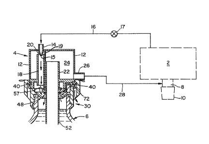
- With reference to the drawings, the home
: ,,
- carbonation apparatus shown comprises a carbonation
~ 10 ohamber 2 provided with means, such as described in
. ~
above-mentioned U.K. Application No. 216108~A, for
carborating water; a concentra~e metering unit 4; a
concentrate supply bottle 6;~ and: an arrangemen~ ~ a~
~; .
~ the bottom: o~ the: carbon~ation. chamber ~or dis¢harging
.'~ 15~ carbonated~ water and- concentrate ~rom the apparatus
.~ into, for example~, a glass 10-.
i The metering unit 4 comprises a housing 12 having
~ ~,
~. a carbon dioxide inlet 14 connected by a conduit 16,
,i ''~ ,
~ incorporating an electrically operated valve 17, to
'~i, 20 the carbonation chamber 2 for receiving carbon dioxide
'.~ gas remaini.ng in the chamber 2 after a carbonation
;;~
~ operation, which gas is under pressure. The lower end
;: ~
o~ the inlet pipe 14 is tapered to form a nozzie 15 and
positioned within a vertical pipe 18 su~h that an
annular gap 20 is formed bet~een the nozzle 15 and pipe
.` 18 to constitute a ventur. A vertically ex~ending
~ ' ' . - " . - ,: . -
.",.
: ~i
.:: . ~ :
,
13282~8
. --6--
-- .
.concentrate inlet pipe 22 is positioned inside the
housing 1~ adjacent the pipe 18- but the pipe 22
terminates, at its top end, at a level lower than that
... .
: of the top end of the pipe 18. The interior of the
housing 12 defines a concentrate metering chamber 24
'into which concentrate may be supplied via the pipe 22.
A partition 19 extends ~rom top~to bottom of the
chamber 24 in between the pipes 1~ a~d 22. The
vertical edges 21 of the partition 19 are spaced from
"
: 10 the interior of the housing so that the portions of the
',~ chamber 24 on opposite~sides of the partition 19 are in
:.'~ communication with ea¢h othe~. A concentr~te outlet 26
provided near t~e bottom of~the chamber 24 is connected
;i3~ by a pi:pe 2~,to the d~is~harge arrangemen~
The bot~le ~ is prov~ide~ wlt~ ~ cap 3~ ~ecured to
the botb1e 6 b:y the interr-ergagement o~ an external rib
32 on the bottIe with an:internal recess~3~ in the cap.
The cap 34 is provided at opposite sides with a pair of
latches 38 each having a downwardly inclined resilient
~i.,;~
:~ ~ 20 nose 40 whioh engages in an annular recess 42 formed in
'l: a boss 44 provide~ on the metering unit 4 at the bottom
., ,
;~ . thereof. The boss 44 has a tapered surface 46 which is
~1 such as to deflect the noses 40 outwardly, when the cap
~ `30.is ~itted to the boss 44, the arrangenent being such
-iJ ~ 25 that the noses 40 snap into the recess 42 once they
.~ ~ ' . . .` ' .
; :1, : : .~ . .
. ~ . . : , ,
3~
; .:, . .
::~J:
,,
7 132~248
: ``
have passed the surface 46 thereby locking the bottle 6
in its operative position.
: A baffle structure 48 provided inside the cap 30
has a central opening 50 which receives a dip tube 52
which extends substantially to the bottom of the bottle
6. The dip tube 52 has at its top end an outwardly
directed flange 54 having at one side an upward
; projection 56 that engages in a corresponding recess 58
'A, in the boss 44. A sealing ring 57 is positioned
: . 10 between the boss 44 and the top of the dip tube 52.
. Opposite the projection 5~, the flange~ 54 is provided
,.~ with a gap 60 which,~ when th~ projec~ion 56- is
:i
correctly engaged wi~h the ~ecess 5~ is opposite the~
lower end of the piipe tg s~ t;hat ~a~bon di~o~h~e.~as may
~?~
flow downwardl~ from t~e. pip~ 1~ tQwa~C, t~e ~a~le~
structure 48. This struc~u~e 4ff oompr~ses a ~cwnwardly
inclined annular baffl~ ~2.,~a frustoconi¢al. i~ner wall
r~, 64 which extends upwardly from the inner edge of the
.~;$~ I baffle 62 and contains a plurality of apertures 66~ and
." 20 a plurality of radial baffles 68 equi-angularly spaced
,i l
around the structure and integral with both the baffle
62 and the wall 64. Thus, carbon dioxide gas entering
the cap .30 from the pipe 18 encounters the annular
~7i baffle 62 which diverts this down~ardly moving gas
inwardly through ~he apertures 66. As:is best seen in
~ Figure 1., the upper edges of the radial baffle 68
...3~
:`3
. .
.
,~ ~
::`.`, : . ~ ,.,.. . . . ., . ;
`; 132~2~8
;
engage the undersurface of the flange 54 so that the
gas passing down the pipe 18 and through the gap 16
. .
enters a compart~ent de~ined between an adJacent pair
of the radial baf~les 68 and the annular baffle 62 and
this gas can only escape from this compartment by
passing inwardly through the relevant aperture 66.
: ,;.
.. Thus, oircumferential movem~nt of t~e gas is prevented
.`<~ by the baffles 68.
:~ As indicated at 70, the underside of the
,:
~ 10 projection 56 is hollow. The hol.low 70 is in register
., with. a passage 72 formed in the boss 44 to ~efine
: . .,
. ' together with She immedia~eIy adjacen~ aperture 66, a.
~.. i ~
: rou~ o~ e~hà~st; ~,f carbon dioxi~e: gas from the
~i: bottl:e. ~
1~5 ~ e~atio~! o~ he~ appa~atus, water in the
;:`1
ca~bona~o~ cKamber 2 ~s ca~bona~ed. Preferably, the
appa~atus ~s su~h that the chamber 2~; is charged with
' ! ' ~ ~ :
su~fioient water ~or making only a single drink during
each carbonation operation. Followîng completion of
~ 3
.s 20 the carbonation operation, carbon dioxide under
. j .
:, pressure, for .example a pressure of 100 psi, is -
. ,,;.
supplied. from the chamber 2 through the valve 17,
preferably under electronic control, to the inlet 14,
! ' 'from which it flows downwardly through the pipe 18,
.25 oreating, by mean~ of .the venturi 20, a reduced
..pre~ure in.the metering ohamber 24. Thi~ cau e~
~,.. . . .
., ,~
..... .
. ~
.... . . . .
; ~.,. , , ~:
~32,~2~8
g
concentrate to be drawn upwardly through the dip tube
.52 and the pipe 22 into the metering chamber. Although
the partition 19 prevents the concentrate from being
drawn directly into the venturi 20, inevitably some
concentrate will be entrained by gas in the venturi 20
:.and hence recycled via the pipe 18 into the bottle 6.
...The baffle structure 48, in ensuring-that the carbon
.~dioxide gas entering the bottle 6 cannot pass directly
to the exhaust route, ensures that such entrained
..10 concentrate is not ejected through the exhaust 72 but
~rather is discharged back irto the bottle. Further,
.. , the. baffte structu~e Ll& ensures that the gas enterin~
the 6Ottle- ~om the p}pe 1~ car,not impinge directly
upon the surfac~ Q~ the ¢oncentrate9. thus preventin,~J
upwar~. splashln,g;~ o~ thi~ eoncerltrate a c:onseq~uence of
: wh.ich cou;~d be that splashed ~o~æe~trate cuul~ b=e
,
~l~exhausted- through the exhaust 72.
.`~After an appropriate interval, the valve 17 is
~ `closed, again preferably under electronic oontrol, the
:'`',
interval being sufficiently long to ensure that the
metering chamber 24 is filled at least to the level of
.,the top o~ the pipe 22. This, particular level defines
~the top level c~f the liquid in the`metering chamber 24
`ii . ;. sinioe, if~the chamber 24 is fillèd to above this level,
~ : . 25 any exces~ may be~r~eoircu1ated via the venturi while
:'~ i. , ., ' ' ' . , ., '
./, '
; ~32~2~
--10--
, ~
the gas ~low continues or will drain back into the
bottle via the pipe 22 after the gas flow ceases.
,~; When the carbonated water is discharged from the
,~
`' chamber 2~ concentrate is also discharged, via an
: .~
appr~priate valve (not shown) in discharge
~`; arrangement 8, from the chamber 24, preferably under
l;' gravity, into the glass 10, this being~ permlt~ed since
the spa~e abo~e the level of liquid in the chamber 24
is connected to atmosphere via the venturi 20, pipe 18,
cap 30 and exhaust 72. In this way an accurately
, .~,
metered quantity of corcentrate appropriate to making a
s~ngle d~irk is dispensed.
A~ ¢arbon dioxide~ atmosphere remains in ~he
bottle 6;~above ~be level of~ Goncen~rate~ thus~ai~ing in
~preservlng the concentrate~ from oxidation.
When the concentrate ir. the bo~tle 6 has been
onsumed-, it may be disconnected ~rom the unit 4 by
,,
`~ pullIng the latches 38 outwardly with the aid of pull
tabs 74 as indicated in Figure 3. To ensure that the
bottle cannot be reused (for example to avoid it being
,. :,
reused filled with an unsuitable liquid) the latches 38
l are constructed so that they break o~f when pulled
outwardly~as shown ir. broken lines in Fig. 3, for which
... . .
: 3 purpose a weak hinge line. is ~ormed at 76 which permits
/ ~ : z5 :~the outward moYement and the breaklng ~off. :- .
,j .
.,,,; ~ .
, ,j.
~ 1
, i
132~2~
Preferably, the cap 30 is an integral plastic
;~ moulding. The bottle 6 may also be plastic. Further,
the metering unit 4 may be constructed as an integral
: plastic moulding. As shown in Figure 3, the bottle 6
may be provided with a foil lid 80 adhesively secured
to the cap 30 9 the lid being removed before use of the
concentrate. After removal of the l~d, the dip tube 52
is inserted via the aperture 50 and then the bottle and
~` dip tube are assembled with the unit 4, with the seal
57 located therebetween. The construation of the
` baffle structure 4~ is such that the angular
- orientation o~ the cap~ relative to the dip tube and the
unit 4 is ir~elevar.~i, although in practice, the
compartment (not shown)~ ~or containing the bottle in
the apparatus may be such that a particu~ar ang~ular
~rientation of the bot~ile has to be selected toi~ende~
~; theipulli tabs 74 ac~essible.
.,.;,; . . . . . .
;i 20
, :i
` ;1 -
... , ~. ji . .
~'.1 '
,~,, : ~
.:; ~ , ' . , , :
,";, ' ' ; '~ ' ' . :
., ~,~ , ,
: ;;, : - , . . . ;
;l . i , .. . .
{ . .- ' - , ~ , . . - .. :. -
. ~, . . . . .
:: ,i . '
" ., ~ . ` . ' ,