Note: Descriptions are shown in the official language in which they were submitted.
1 32~293
DN7792 - Hatcher
SUPPORT
Technical Field
The present invention relates generally to a support, and more
particularly to a support which is adapted to secure a lap type
computer to a car seat in such a manner that it may be readily uti-
lized by the user, and which will be secure when the car is underway.
Background of the Invention
In recent years a form of computer has been developed which is
generally referred to as a portable computer or a lap top computer.
This form of computer is easily portable, and is provided with an
LCD screen. Route salesmen may use such a computer to review a data
base before visiting a customer. Since the route salesmen typically
utilize cars it is desirable that a computer support be developed
wherein the computer may be utilized within the car and held in a
secure manner while the car is in use.
Objects and Summary of the Invention
It is an object of the present invention to provide a support
wherein a portable or lap type computer may be secured to the sup-
port, the support in turn being secured to a car seat so that the
support is secure during operation of the car
More particularly, it is an object of the present invention to
provide a support for securing a lap type computer to a car seat,
which support has various features of adjustment so that the compu-
ter may be properly positioned for ease of use and viewing by the
user of the computer.
~ - ,
- :: , ..
1 328293
Hatcher 2-
The above objects and other objects of this invention are
accomplished by providing a support having upper and lower pivotally
interconnected units, the lower unit carrying a belt so that it may
be belted to the car seat, and the upper unit in turn carrying a
belt for the purpose of securing the lap top computer to the upper
unit. In order to provide for suitable adjustment of the computer
for ease of viewing and use, the lower unit is provided with a pair
of opposed downwardly extending legs, one of which legs may be
secured in various positions of vertical adjustment. The upper and
lower units, which are pivotally interconnected to each other for
swiveling movement of the upper unit with respect to the lower unit,
are provided with means to secure the upper unit in various posi-
tions of swiveling adjustment. In addition, the upper unit is pro-
vided with a vertically adjustable auxiliary support so that the
angle of inclination of the lap type computer may be varied.
The foregoing will become more apparent after a consideration
of the following detailed description taken in conjunction with the
accompanying drawings in which a preferred form of this invention is
illustrated.
Brief Description of the Drawings
Figure 1 ls a perspective view showing the support of this
invention mounted within a car, and a lap type computer mounted upon
the support.
Figure 2 is a plan view of the support shown in Figure 1, the
upper unit of the support being shown in ~ull lines in one extreme
position of adjustment, and in broken lines in another extreme posi-
tion o~ adjustment.
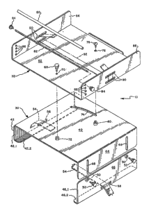
Figure ~ is an exploded isometric view of the support shown ln
Figure 2.
: . ,. ~ ~ . . ,
' : ' ~'' , ~ ' ~ -.
~ ~ .
1 3282q3
Hatcher -3-
. .
Figure 4 is a side view of the support showing the manner in
which it is mounted on a car seat.
Figure 5 is a rear elevational view of the support.
Figures 6, 7, 8 and 9 are sectional views taken generally
along the lines 6-6, 7-7/ 8-8, and 9-9 in figure 2.
Detailed Description
-
With reference to the drawings, the support of this invention
is indicated generally at 10. As shown in Figure 1, the support is
shown mounted on a car seat 12, a portable or lap top co~puter,
indicated generally a~ 14, being mounted thereon. This type of
computer is typically provided with a rigid base 16 which extends
the length of the computer, a forward portion of the base being
provided with a keyboard 18. Hinged to the base is a keyboard cover
20 which is provided with an LCD screen 22. This form of computer
constrùction is well-known in the art. Such computers today typi-
cally have 512K or more Random Access Memory (RAM) and either one or
two disk drives. When used by a route salesman, a disk is frequent-
ly loaded with customer data base information and the route salesman
can access this information prior to visiting a customer, and this
information can be updated after the route salesman's call, in addi-
tion to the route salesman entering orders. Therefore, as pointed
out above, it is desirable that the computer be mounted in the car
for ready access by the user of the computer or route salesman.
Referring now in greater detail Figures 2 to 4, the support of
this invention conslst of a number of major components, these being
a lower unit, indicated generally at 30, and an upper unit, indi-
cated generally at 32, which is moun~ed upon the lower unit by pivot
means, indicated generally at ~4 in Fig. 4, ~or adjustable swiveling
, . . : .
1 328293
Hatcher -4~
positioning. Mounted upon the upper unit is a vertically adjustable
auxiliary support, indicated generally at 36. In addition to these
major components, first and second holding means are provided to
hold the lower unit 30 to the car seat 12, and to hold the computer
base 16 to the upper unit 32, respectively.
As can best be seen from Figure 3 the lower unit includes an
upper intermediate planar portion 40 formed of sheet metal or the
like and a pair of downwardly extending legs. The front leg 42 is
preferably formed integrally with the portion 40 and includes a
vertical portion 42.1 and a lower rearwardly extending flange por-
tion or foot portion 42.2 which is adapted to rest upon a front edge
of the car seat 12. The rear leg 44, 4~ is vertically adjustable
and is therefore ~ormed of separate components. Thus, the upper
portion of the rear leg is a vertically extending member 44 which is
formed integrally with the upper intermediate planar portion 40.
The lower portion 46 of the rear leg is also formed of sheet metal
or the like and includes a vertical portion 46.1 and a foot portion
46.2. In order to provide for vertical adjustment of the rear leg
44, 46 the upper portion is provided with a pair of spaced apart
vertical slots 48. In addition, the vertical portion 46.1 of the
lower portion of the rear leg is provided with a pair of apertures
(no number) which are adapted to be positioned in alignment with the
slots 48, fastener receiving means in the ~orm of weld nuts 50 being
secured to the portion 46.1 about the apertures. Threaded fasteners
52 are adapted to be passed through the slots 48 and secured within
the fastener receiving means 50 to secure the parts together, the
threaded fasteners having enlarged knurled heads which can be easily
engaged by hand. As can best be seen from Figure 4 the back of a
seat in a car is typically disposed at a lower position than tile
front of the seat, and the angle may vary from car to car.
~ .
- . ~,, . , . . ~ -
1 328293
Hatcher -5~
Therefore it is necessary in order to properly position the computer
for use by the operator that the rear leg be adjustable.
First holding means is provided for holding the lower unit 30
onto the seat 12, which first holding means consists of a belt 54,
which belt is adapted to be passed through front and rear horizontal
slots ~6, 58, in portions 42.1 and 46.1, respectively. The belt 54
may be a nylon strap. In any event~ the ends o~ the belt are pro-
vided with suitable fastening means or buckling means 60 so that the
ends of the belt can be secured to each other with the belt firmly
disposed about the car seat.
The upper unit 32 includes a lower intermediate planar portion
6Z and a pair of opposed upwardly extending legs, the front leg
being indicated at 64 and the rear leg at 66. As can best be seen
from Figure 1 the width of the planar portion 62 between the legs 64
and 66 is of such a width that the base 16 of the lap top computer
may be confined between the legs. The upper unit 32, like the lower
unit 30 is typically formed from essentially a single piece of sheet
metal which is bent into the desired configuration.
The pivot means 34 consists essentially of a threaded fastener
68 having an enlarged head which can be manually engaged, which
threaded fastener is adapted to be passed through a suitable aper-
ture 70 in the lower intermediate port~on 62 of the upper unit, and
then through an aperture (no number) in the upper intermediate
planar portion 40 of the lower unit 30, the threaded fastener being
received by fastener receiving means in the ~orm of a weld nut 72
secured about the aperture in the lower unit. As the upper unit
will be moved between a position wherein the legs are parallel to
the seat back to an alternate position shown in broken lines in
Figure 2, it is des~rable that the pivot means be positioned
" -~
.
1 328293
Hatcher -6-
relatively close to the operator so that the back of the upper unit
32 does not contact the seat back as the unit is moved to its
various positions of adjustment. Thus, the pivot means is disposed
adjacent that edge of the lower unit which is adapted to be posi-
tioned closest to the user.
In order to hold the upper unit on the lower unit in various
positions of swivel adjustment an arcuate slot 74 is formed on the
upper intermediate planar portion 40 of the lower unit, and an aper-
ture 76 is formed on the lower intermediate portion 62 of the upper
unit 32, which aperture 76 is adapted to be placed in register with
the siot 74. A screw 78 is adapted to extend through the aperture
76 and slot 74 and be held by a nut 80. If the lap top computer is
not in the proper position for use by the operator, it is only
necessary for him to loosen nut 80 and to reposition the upper unit
on the lower unit until it is in the desired operating position, at
which time he would then retighten nut 80. While a slotted head
screw 78 is shown, it should be obvious that this could be replaced
by a carriage bolt or any other suitable fastener.
The vertically adjustable auxiliary support means ~6 consists
essentiall,y of a rod 82. The ends of the rod 82 are threaded and
are adapted to receive nuts 84. The rod 82 is disposed in varying
positions of vertical adjustment by positioning it in vertically
aligned apertures 86, which apertures are disposed at that end of
the ~ront and rear legs 64, 66 which is closest to the computer
operator. As can be seen from Figure 1 a lower forward portion of
the computer base 16 is adapted to rest upon the rod. In order to
protect the base from being scratched and to improve the frictional
coefficient between the auxiliary support 36 and the base of the
computer, the rod is covered with a soft tube 88 of vinyl, rubber or
the like.
.
i . .
1 32g293
Hatcher -7-
In order to secure the computer base to the upper unit 32 each
of the legs 64, 66 is provided with a pair of spaced apart parallel
horizontally extending slots 90. Second holding ~eans in the form
of a belt or strap 92 is adapted to be passed through the slots as
best indicated in Figure 3, the belt 92 being provided with a buckle
94 of conventional design. The particular buckle shown is o~ the
type sold under the model designation "FASTEX #SRI" by ITW Nexus,
and covered by U.S. patents 4,150,464 and 4,171,555. While this
type of buckle or fastener is desirable, other forms of buckles may
also be employed.
The support of this invention is utilized by positioning it on
a seat in the manner shown, securing the lower unit 30 by means of
lower belt or strap 54. In addition, a seat belt may also be passed
underneath the lower unit to secure the rear leg assembly 44, 46
adjacent the back of the seat, this feature not being illustrated in
the drawings. If the angle of the support surface 62 is not cor-
rect, the length of the adjustable rear leg 44, 46 will now be ad
justed to position the support surface 62 at the correct angle for
the operator. The upper unit will now be swiveled to its desired
position and secured in place by nut 80. The lap type computer will
now be mounted on the unit and if the keyboard is either too low or
too high the rod 82 will then be adjusted to place it in the proper
position. It is now only necessary to strap the computer in place.
While the support of this invention shown in the accompanying
drawings and described above has been designed primarily for use
with a lap top computer, it should be obvious that the support of
this invention can be used for other purposes. Thus, a clip board
or equivalent attachment may be provided which can be secured to the
upper unit, the support being adjustable so that attachment can be
positioned to provide a proper writing surface for the user.
~ . . . . .... ...
" , , ~ ' "
1 328293
Hatcher -~-
Alternatively, a clip board or equivalent unit can be substituted
for the upper unit shown and described above. Accordingly, while a
preferred structure in which the principles of the present invention
have been incorporated i5 shown and described above, it is to be
understood that this invention is not to be limited to the particu-
lar details shown and described above, but that, in fact, widely
differing means may be employed in the broader aspects of this
invention.
What is claimed is:
.