Note: Descriptions are shown in the official language in which they were submitted.
~328~04
PD-87352
MICROSTRI~ ANTENNA SYSTEM WITH
MULTIPLE FREQUENCY ET~MENTS
BACKGROUND OF THE INVENTION
This invention relates to an array antenna constructed
of microstrip elements and, more particularly, to an
array antenna wherein each element is formed of a
plurality of radiators tuned to radiate in different
freguency bands.
Microstrip antenna systems are employed advantageously
in spacecraft and other environments requiring a
compact antenna structure. An array antenna is
constructed readily from a board which is formed of
dielectric material and is clad with metallic sheets on
opposed surfaces of the board. An array of pad-shaped
antenna elements interconnected by electrically
conductive metallic strips is etched rsadily from a
metallic sheet on one side of the board.
Photolithographic techniques may be employed in the
etching to facilitate manufacture and to provide for
high precision in the formation of the antenna elements
and the interconnecting conductors.
The electrical characteristics of a microstrip antenna
element are of particular interest in the design of an
individual antenna element, as well as in the design of
an array of the antenna elements. The thickness of the
original board determines the distance between an
antenna element on one surface of the board and a
. ~ .
... .
...
. .
.
:~ .
-
~r `~
2 1328~04
ground plane provided by the metallic sheet on theopposite surface of the board. The electrical
characteristics are influenced by the distance between
element and ground plane. In terms of the
S electromagnetic operation of a pad-shaped antenna
element, the physical structure of the element spaced
apart from the ground plane may be likened, for
purposes of analysis and understanding of the
operation, to an open walled cavity which resonates at
lQ specific electromagnetic modes, and with a relatively
high value of Q, the ratio of energy stored to energy
dissipated per cycle of electromagnetic signal.
As an example in the effect of the distance between
element and ground plane upon the electrical
characteristics, it is noted that a decreasing of the
distance increases the Q of the open-walled cavity,
suppresses the development of surface waves which can
propagate from element to element along the surface of
the array, suppresses blind angles in the viewing of
sub~ect matter during a scanning of a beam radiated by
the array, and reduces bandwidth to signals which are
to be transmitted or received by the array of antenna
elements. This dependency Or electrical characteristics
upon the distance between element and ground plane has
necessitatad a compromise in the choice of the
electrical characteristics rOr a microstrip array
antenna. For example, if the distance has been
decreased to avoid surrace wavQs and scan blindness,
the resultant antenna may have too narrow a bandwidth
to be userul for the perrormance of a desired mission.
3 1328504
The lack of sufficient bandwidth creates a problem in
two areas. One area relates to the transmission of a
broadband signal, this being a signal having a
bandwidth larger than that provided by the foregoing
antenna element. The second area of concern relates to
the generation of a fan beam which is to be scanned by
variation of a frequency of the electromagnetic
radiation. By way of example in the generation of such
fan beams, one common configuration of an antenna
comprises a set of antenna elements, or subarrays which
are interconnected by fixed delays. A variation in the
frequency of electromagnetic radiation introduces a
variation in phase shift among signals outputted by
successive ones of the antenna elements or subarrays.
A successful scanning of such a fan beam presupposes
that each of the antenna elements or subarrays has a
sufficiently wide bandwidth to accommodate the shift in
frequency. However, in the case of presently available
microstrip array antennas, the narrow bandwidth unduly
limits the transmission of broadband signals, and the
use of a freguency-scanning fan beam.
SUMMARY OF THE INVENTION
The foregoing problem is overcome, and other advantages
are provided by a microstrip antenna system wherein, in
accordance with the invention, each of the antenna
Qlements is formed a~ an array o~ radiators with each
radiator of an antenna element being configured to
resonate at a ~requency different from other radiators
of the antenna element. For example, a set of three or
four radiators may be employed in the construction of a
o1ngle antenna eloment. Each radlator has the form of a
~ .
4 132850~
square pad, it being understood that the pad may have
some other form such as a rectangular or circular shape
for providing a specific radiation characteristic. In
particular, it is noted that a square-shaped pad with a
slot therein extending diagonally is useful in the
generation of a circularly polarized radiation.
In accordance with a further feature of the invention,
each of the radiators of a single element are
configured to transmit and receive radiation in
separate frequency bands wherein frequency bands of a
succession of the radiators are disposed in the
spectrum as a succession of contiguous
transmission/reception bands. In the ensuing
discussion, the invention will be taught with reference
to the transmission of radiation, it being understood
that the antenna operates in reciprocal fashion for
receiving incoming electromagnetic signals. By way of
example in the construction of a set of the radiators
in a single antenna element, the radiator nearest the
feed has a larger size for transmission at a
low-frequency portion of the transmission band, a
second of the radiators has a smaller size for
transmission of signals at mid-band frequencies, and a
third of the radiators has a still smaller size for
transmis~ion of a high-frequency portion of the band.
The radiators are connected by ferrite circulators.
operation o~ the circulators wlth the radiators may be
demonstrated with reference to the foregoing example of
three radiators tuned to different frequencies. The
lowest frequency radiator is connected via a first
circulator to the feed. The second radiator is
' ~
. .
13285~4
connected via a second circulator to an output
terminal of the first circulator. The third
radiator is connected to an output terminal of the
second circulator. By way of example,
electromagnetic radiation including a low-band
signal, a mid-band signal, and a high-band signal
is fed to a first port of the first circulator.
These signals are outputted by a second port of the
first circulator to the first radiator. The low-
band signal radiates from the radiator and the mid-
band and the high-band signals are reflected back
to the first circulator. These signals then exit a
third port of the first circulator to enter a first
port of the second circulator. The second
circulator outputs these signals to the second
radiator which radiates the mid-band signal while
reflecting the high-band signal back to the second
circulator. The second circulator then outputs the
high-band signal from a third port to the third
radiator. In this way, each of the radiators of an
antenna element receives and transmits a specific
portion of the overall signal band enabling the
antenna element to radiate a signal having a
bandwidth equal to two, three or four times the
bandwidth of a single radiator, depending on the
number of radiator~ or circulators employed.
Embodiments of the invention wlll be described to
demonstrate a plural-radlator antenna element for a
phased array antenna transmitting a broad bandwidth
signal without use of a reflector, and for a
frequency-scanning fan beam reflector antenna
system useful ln the communication of signals from
a satellite to stationary or mobile receivers, or
transcelvers, at various locations on the earths
surface.
'
6 1328504
In one embodiment of the invention, a complementary
microstrip antenna system, which may be configured as a
planar array, illuminates a reflector to provide
frequency scanned beams. This antenna system offers
significantly reduced complexity, smaller size, lower
weight and reduced RF losses. This antenna system of
this embodiment of the invention can be operated
without need of a beam forming network, a confocal
reflector system, a Butler matrix nor a large bulky
direct radiating array.
Another aspect of this invention is as follows:
An antenna system comprising:
an array of microstrip antenna elements, each of
said elements comprising a first radiator, a second
radiator, and a circulator;
power dividing means connected to an input terminal
of each of said antenna elements; and wherein
in each of said elements, said circulator has a
plurality of ports, a f irst of said ports connecting at
said input terminal with said power dividing means, a
second of said ports connecting with said first
radiator, and a third of said ports connecting with said
second radiator;
in each of said elements, said second radiator is
operative to radiate in a second frequency band higher
than a first radiation frequency band of said first
radiator, said first radiator reflecting radiation of
said second frequency band via said circulator to said
second radiator;
said power dividing means transmits radiation
occupying the frequency bands of both radiatorq via said
circulator in each of said antenna elements towards the
input terminal in each of said elements; and
corresponding ones of the radiators of said antenna
elements are spaced apart with predetermined spacings
for generation of a beam of radiation by the antenna
system.
A
.
., .
6a 1328504
BRIEF DE~Ip~loN OF THE DRAWING
The aforementioned aspects and other features of the
invention are explained in the following description,
taken in connection with the accompanying drawing
wherein:
Fig. 1 is a diagrammatic view of an antenna system
including a phased array antenna constructed of
microstrip antenna elements wherein each element is a
plural-radiator elemont in accordance with the
invention, the antenna being employed for the
transmission of a broad-band signal;
F$g. 2 i~ an onlarged simplified plan view of an
antenna olement of Fig. 1:
Fig. 3 is a fragmentary sactional view of a radiator
taken along the line 3-3 in Fig. 2;
Fig. 4 ~how~ a plan viow of a radiator having an
alternate configuration:
7 1328~
Fig. 5 is a set of graphs showing frequency
responsivity of a set of radiators of Fig. 1;
Fig. 6 shows an antenna system reflector feed
employing the plural-radiator microstrip antenna
elements of the invention for the generation of a
frequency-scannable fan beam;
Fig. 7 is a stylized schematic view of a satellite
carrying the antenna system of the invention with a
reflector for scanning fan beam across various
portions of the earth;
Fig. 8 shows a modified configuration of the
antenna element of Fig. 6 wherein a single
parasitic element is disposed between successive
ones of the radiators;
Fig. 9 is a further modification of the antenna
element of Fig. 6 wherein two parasitic elements
are disposed on opposite sides of each of the
radiators; and
Fig. 10 shows three antenna system reflector feeds,
such as that of Fig. 6, disposed on a common board
for illumination of three separate portions of the
earth's surface, each of the antenna systems
producing a scannable fan beam for scanning a
specific one of the portions of the earth's
surface.
DETAILED DESCRIPTI~N
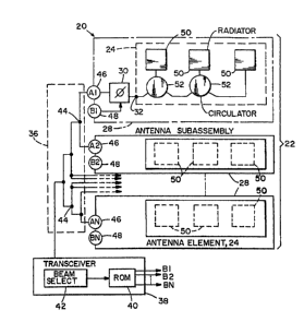
Figs. 1 - 3 show an antenna system 20 constructed in
accordance with the invention. The system 20 includes
- . , . ~
' ~ ~
1~28~0~
an array antenna 22 which comprises an array of antenna
elements 24 each of which is constructed of microstrip
on a dielectric slab 26 (Fig. 3). Each antenna element
24 is formed as a part of an antenna subassembly 28
which also includes a phase shifter 30 connected to an
input terminal 32 of the element 24. Also included
within the system 20 is a power divider 36 connected
to a transceiver 38, and a read-only memory 40 which
stores phase shift commands for the phase shifters 30
for development of a beam of radiation transmitted by
the antenna 22. As a convenience in describing the
invention, the transceiver 38 and the antenna 22 will
be described in terms of generating and transmitting a
beam of electromagnetic radiation, it being understood
that the antenna system 20 is reciprocal in operation
so that the description applies equally well to a
reception of electromagnetic signals.
The transceiver 38 includes circuitry (not shown) for
transmitting and receiving electromagnetic signals.
Also included in the transceiver 38 are the memory 40
and a beam selector 42 which addresses the memory 40
to select the set of phase shirt commands for
generating a beam in a specific direction. The beam
can be redirected by selQcting a different ~et of phase
~hifts for the varlous phase shifters 30. The selector
42 may be a digital encoder whlch is manually operated
to select a beam direction, or may be an address
generator of an automatic beam scanning ~ystem. The
power divider 36 comprises a set of power splitters 44
which are connected in the arrangement of a corporate
feed ~tructure, each o~ the 6plitters 44 dividing
incident transmitted power equally among the two
:; ;,.
.. . .
,
. . ,
-' 1328~04
branches of the splitter. The power divider 36 couples
power from the transceiver 38 in equal amounts, via
input terminals 46, to the phase shifters 30 of the
respective subassemblies 28. Command signals from the
memory 40 are coupled via input terminals 48 to the
phase shifters 30 of the respective subassemblies 28.
Individual ones of the terminals 46 are identified by
legends Al, A2, . . AN; individual ones of the
terminals 48 are identified by legends Bl, B2, . . BN.
Each of the antenna elements 24 comprises radiators 50,
three such radiators being shown by way of example, it
being understood that, if desired, only two of the
radiators 50 might be employed or, alternatively, four
or more radiators 50 might be employed in the
construction of an antenna element 24. For ease of
reference, the three radiators 50 are identified
further in Fig. 2 by the legends J, K and L. The three
radiators 50 are interconnected by ferrite circulators
52 which, for convenience, are identified further in
Fig. 2 by the legends D and E. The number of
circulators 52 required to interconnect the radiators
50 i9 one less than the number of radiators. Thus, in
the case of the three radiators 50, two of the
circulators 52 arè employed. Only one circulator 52 is
required in the event that the antenna element has only
two radiators. In the case of an antenna element
having four of the radiators, then a total of three of
the circulators 52 are required for interconnection of
the radiators.
With reference to the construction of the antenna
element 24 with radiators 50, the first circulator D
.,
- ~ , .
132850~
interconnects the radiator J via the input terminal 32
to the phase shifter 30. The second circulator E
interconnects the first circulator D, the second
radiator K, and the third radiator L. Each of the
circulators 52 comprises a ferrite disk 54 located
between two centrally disposed magnets 56, one on
either side of the dielectric slab 26 (only a top one
of the magnets 56 being shown in Fig. 2). In each
circulator 52, the ferrite disk 54 acts in response to
a constant magnetic field provided via the two
centrally disposed magnets 56 to provide for an
encircling guidance of electromagnetic waves about the
circulator 52 . In accordance with a well-known
construction of the circulators, three ports are
provided, the three ports being spaced uniformly at 120
degree angles about the disk 54 to provide for a
combination of the circulating waves for the
transmission of power from one port to the next port.
Both of the circulators 52 operate in the same fashion,
so that only the operation of the circulator E need be
described. Power entering a first port El exits at a
second port E2. Power entering port E2 exits at port
E3. Power entering port E3 exits at port El. The
combination of the circulating waves provides that
essentially all of the power exits from only one port
with no more than a negligibly small amount of power
exiting from the remaining port.
As shown in Fig. 3, the antenna element 24 includes a
ground plane 58 which is ~ormed as a sheet of metal,
such as copper or gold, disposed on a back surface o~
the slab 26. The radiator 50 is formed as a metallic
`, . ! ~ , , ~ .
: ' ~
.`' .
'`
ll 132850~
pad, which may be of the same metal as the ground plane
58, disposed on a front surface of the slab 26 opposite
the ground plane 58. The configuration of the pad of
the radiator 50 being spaced apart from the plane 58
with dielectric material of the slab 26 therebetween is
recognized as being the configuration of a capacitor,
and also the configuration of an open-walled cavity
resonator. It is this mechanical configuration which
gives the electrical characteristics to the radiator
50, particularly in terms of such bands of fxequency of
electromagnetic waves which may be radiated from a
radiator 50, or reflected from the radiator 50 back
into a circulator 52. Metallic strip conductors 60
interconnect the radiators 50 with the circulators 52.
Sections of the conductors 60 which enter into a
circulator 52 are tapered towards the center of the
circulator 52, in accordance with the usual practice in
the formation of the circulator ports.
Fig. 4 shows a configuration of radiator 62 which has a
square-shaped configuration, and is provided with a
diagonally oriented slot 64 which provides for a
circular polarization to electromagnetic waves radiated
from the radiator 62. The radiator 62 is excited by
way of a strip conductor 60, as is the case with the
radiators 50 o~ ~ig. 2. In the ensuing deacription of
the operation o~ the invention, re~erenc~ wlll be made
to the radiators 50, it being understood that the
description Or the operation applies also to radiators
having a dif~erent con~iguration such as the radiator
62.
.
.
12 1328~0~
The operation of the antenna element 24 may be
explained with reference to the graphs of Fig. 5. Each
of the radiators J, K, and L radiate in a specific
frequency band, these bands being indicated by the
legends J, K, and L in the upper graph of Fig. 5. A
further trace M, shown in dashed line, is provided to
demonstrate the radiation characteristic of yet a
fourth radiator, if such radiator would be present as
is the case for further embodiments of the invention to
be described. An important characteristic of the
radiators 50 is the fact that each radiator reflects
back to a circulator 52 such portion of radiant energy
lying in a spectral region at higher frequency than the
radiation band of the radiator. The radiators of an
antenna element are constructed with slightly different
configurations or dimensions, or are loaded to offset
their frequency characteristics. This is demonstrated
in the lower graph of Fig. 5 wherein traces of the
graph are similarly labeled with the legends J, K, and
L to correspond to the radiators J, K, and L. The
radiator J is shown to radiate electromagnetic energy
at frequencies within its radiation passband, but to
reflect radiant energy at frequencies above the
passband. Similar comments apply to the radiators K,
and L , a~ well as to a fourth radiator, shown in
phantom, for an embodiment of the invention having four
radiators.
With respect to Figs. 1 and 2, the foregoing principles
o~ operation provide the ~ollowing very useful result.
A broadband signal can be transmitted by the
transceiver 38 via the antenna element 24, even though
the signal bandwidth is broader than the radiation band
' . ' ' '
13 132850~
of any one of the radiators 50. Assuming, by way of
example, that the signal bandwidth extends over the
spectral regions J, K, and L of Fig. 5, then all of the
power is incident via the input terminal 32 and via the
circulator D to the radiator J. The spectral portion
of the radiation band of the radiator J is radiated
into space, while the spectral portions of the
electromagnetic energy for the radiators K and L is
reflected back from the radiator J to the circulator D.
The remaining two spectral portions are then
transmitted via the circulator E to the radiator X
wherein the K portion is radiated, and the L portion is
reflected back to the circulator E. The circulator E
then outputs the L portion to the radiator L. Thereby,
the three radiators J, K and L, acting in concert, are
capable of radiating an electromagnetic signal having a
bandwidth three times the size of a bandwidth of a
single one of the radiators 50. If the antenna element
24 employed only two of the radiators 50, then the
bandwidth capacity of the element 24 would be only
twice that of a single radiator 50. In contrast, if
the elements 24 employed four of the radiators 50, then
an electromagnetic signal having a bandwidth four times
that of a ~ingle radiator 50 could be transmitted, and
received, by the antenna elements 24.
With respect to the generation of a beam of radiation
by the array antenna 22, which antenna includes a
plurality of subassemblies 28, having the
aforementioned antenna elements 24 with the three
radiator~ 50, it is noted that the phase shlfter 30 in
each of the ~ubassemblies 28 introduce phase shifts
among signals radiated by the radiators J, in the
.
14 1328~0~
various subassemblies 28. Corresponding phase shifts
are introduced between the corresponding radiators X,
and between the corresponding radiators L of the
various subassemblies 28. Thereby, the signal radiated
in each of the three signal bands receives the
necessary phase shifts to enable the array of antenna
elements 24 to combine the signals for the generation
of a beam in a desired direction relative to the array
of the antenna 22. By way of example in the
construction of the phase shifters 30, each of the
phase shifters may be a 3-bit PIN diode phase shifter
which introduces a phase shift in accordance with a
digital command signal applied at a terminal 48 by the
memory 40.
The physical configuration of the array antenna 22
provides that the radiators J in each of the antenna
elements 24 has a spacing of approximately one-half
wavelength of the radiated electromagnetic waves.
Corresponding spacing is provided between the element
24 for the radiators K and the radiators L. This
spacing provides for a well defined beam pattern
essentially free of grating nulls and grating lobes.
As a matter of convenience in the construction of an
antenna element 24, the phase shifter 30 and the
element 24 may be supported upon a common slab 26. If
desired, a aingle slab 26 can be employed in the
construction of the entire antenna 22 with all of the
elements 24 and the phase shi~ters 30 being constructed
on the same slab 26. Furthermore, the power divider
36, which may be fabricated of strip conductor
elements, can also be placed on the same slab 26 with
the antenna subassemblies 28. This provides for a
.
. . ~
~ ; `
1328~0~
single mechanical assembly for both the power divider
36 and the array antenna 22.
In the embodiment of the invention disclosed in Figs.
1-5, beam generation and steering is accomplished by an
array antenna without use of a reflector. In
alternative embodiments of the invention disclosed in
Figs. 6-lO, a reflector is used in conjunction with an
array antenna for generating and steering a beam.
Fig. 6 shows an alternative embodiment of the invention
wherein an array antenna 66 comprises a set of antenna
elements 68 arranged side-by-side for forming a beam of
radiation. The antenna 66 of Fig. 6 has the same
general configuration as does the antenna 22 of Fig. 1,
except that the phase shifters 30 of Fig. 1 have been
deleted in the embodiment of Fig. 6. Also, in the
embodiment of Fig. 6, each of the antenna elements 68
has a set of four radiators 50 instead of the three
radiators in the embodiment of Fig. 1. Also, in the
embodiment of Fig. 6, each of the elements 68 has three
circulators 52 instead of the two circulators provided
in the embodiment of Fig. 1. For ease of reference,
the radiators SO and elements 68 in Fig. 6 are further
identified by the legends J, K, L, and M, and the
circulators 52 are further identified by the legends D,
E, and F. The explanation of operation di~closed above
with reference to Fig. 5, applies also to the operation
of an ant-nna element 68 of Fig. 6. The construction of
the element 68 employs the same cross-sectional
configuration a8 wa~ disclosed with rePerence to Fig. 3
wherein a radiator 50 is spaced apart from a ground
plane 58 by a dielectric slab 26. Interconnections
- . . . ~ : ~ . .: :
- . ~ .
16 132~5~
between radiators 50 and the circulators 52 of Fig. 6
is provided by strip conductors 60 as was disclosed for
the embodiment of Fig. 2.
The array antenna 66 is part of an antenna system 70
which includes also power divider 72 comprising a set
of power splitters 44. The power divider 72 connects
with each of the antenna elements 68 via their
respective input terminals 46. The power splitters 44
are connected in the arrangement of a corporate feed
structure, each of the splitters 44 dividing incident
transmitted power with a specific ratio among the two
branches of the splitter to provide the desired power
split. A transceiver 78 connects to an input end 80 of
the power divider 72 for applying electromagnetic
signals via the power divider 72 to the antenna
elements 68 for transmission into space as a beam of
radiation. In contradistinction to the broadband signal
transmitted by the system of Fig. 1, the system of Fig.
6 operate~ with a narrow band signal which can be
scanned across the spectral portions J, K, L, and M of
Fig. 5. For example, data may be transmitted by
modulation of a data-carrying signal onto a carrier
frequency at the transceiver 78, which carrier
rreguency may be scanned. The frequency selector 82
within the transceiver 78 allows for manual selection
Or the carrier rrequency, or for an automatic scanning
Or the carrier frequency.
With reference to Fig. 5, it may be appreciated that
the narrowband signal may be scanned across the
composite bandwidth of the four spectral portions of
the radiators J, K, L, and M. Assume, by way of
;; . - : .
.
.
17 1328~4
example, that the radiation frequency starts at a low
value, this being in the spectral portion of radiator
J. Then as the radiation frequency is increased
sufficiently, the radiator J reflects the signal back
through the circulators D and E to radiate out from
radiator K. Tuning of the radiators can be
accomplished by use of a tuning structure such as a
stub, (not shown) or, preferably, as is accomplished in
the preferred embodiment of the invention, by
constructing each of the radiators 50 in an element 68
with slightly different physical dimensions. The
radiators in the embodiment of Fig. 2 are tuned to
radiate at their specific frequencies in the same
fashion as is employed in the construction of the
embodiments of Fig. 6. The radiators J in the set of
elements 68 are spaced apart by approximately one-half
wavelength of the radiated electromagnetic waves,
similar comments applying to the radiators K, L, and M
of the set of elements 68. This spacing among the
radiators provides for a well defined beam pattern.
With reference to Fig. 7, the antenna system 70 may
include a reflector 86 which is curved, typically with
a second order curve such as a parabolic surface about
a focus 88. The antenna 66, shown in phantom, may be
located at the focus 88, and direct radiation towards
the reflector 86 to provide a scanned beam 90.
Typically, the beam 90 is a fan beam. Preferably, as
will be described subsequently with reference to Fig.
10, an antenna system 100 is to be inserted at the
focu~ 88 in place of the antenna 66, a~ shown in solid
lines in Fig. 7. In the antenna system 100, there are
three array antennas 102 of which individual ones are
.
. .. . : .
18 1328504
further identified by the legends E for east, C for
central, and W for west for reasons which will become
apparent in the ensuing discussion.
In the exemplary use of the invention, as disclosed in
Fig. 7, the antenna system 70 is carried on board a
satellite, and the reflector 86 directs a fan beam
towards a portion of the earth 92, here represented as
the United States of America. Scanning of the beam
will be explained with reference to Fig. 10. Such use
of a scanned beam from a satellite permits
communication among stations located at various points
on the earth's surface, which stations have suitable
transmission and receiving equipment for communicating
via satellite. Deployment of the invention in the
satellite configuration of Fig. 7 provides various
advantages which will be described hereinafter.
Fig. 8 shows an antenna element 94 which employs a form
of construction which is an alternative embodiment of
the antenna element 68 of Fig. 6. In Fig. 8, the
antenna element 94 comprises the same radiators 50 and
circulators 52 as was disclosed with reference to Fig.
6, and further includes parasitic radiators 96 which
are $nserted between the radiators 50 which are
actively driven by the circulators 52. The arrangement
of the radiators provides for an alternating sequence
of the parasistic radiators 96 and the active radiators
50. If de~ired, parasitic radiators 96 may be placed
also at opposite ends of the radiator 50 a8 shown in
Fig. 9.
' . ~ ' ' ~ ' '
.
-` 13285D4
Fig. 9 shows an element 98 which is yet a further
embodiment of the element 68 of Fig. 6, and differs
from the embodiment of Fig. 8 in that further parasitic
radiators 96 are employed in the element 98 of Fig. 9.
The parasitic radiators 96 in the embodiments of both
Figs. 8 and 9 are formed as metallic pads disposed on
the front surface of the slab 26 in the same fashion as
was disclosed in Fig. 3 for the construction of an
active radiator 50. Instead of the alternating
sequence of Fig. 8, in Fig. 9, each of the active
radiators 50 is provided with a pair of parasitic
radiators 96, there being one parasitic radiator 96 on
each side of an active radiator 50. Thus, in the
antenna element 98 of Fig. 9, there are twice as many
parasistic radiators 96 as there are active radiators
50. The active radiators 50 are driven by signals from
the circulators 52 in the same fashion as was described
above for the embodiments of Figs. 8 and 6. The
parasitic radiators in the embodiments of Figs. 8 and
9 aid in side lobe suppression of the radiation pattern
of the beam as the beam is scanned across the earth's
surface.
Fig. 10 show6 a configuration of an antenna system 100
useful for the satellite communication situation of
Fig. 7. In Fig. 10, the system 100 includes a set of
three array antennas 102 arranged on a common ~upport
104, which support may be constructed as the ~lab 26 of
Figs. 2 and 3 to serve as a common dielectric support
for all three antennaa 102. A set of three power
dividers 106 is provided on the support 104, individual
ones of the power dividers 106 being connected to
r-~poctlv- on-~ o~ th- ant-nna~ 102. Du- to th- clo~-
.
~ ; ~ .
~: '
~o 132850~
spacing of the antennas 102, there is room on the front
side of the support 104 for only one power divider 106
at the left end of the support 104 and a second power
divider 106 at the right end of the support 104. The
power divider 106 connected to the center antenna 102
is disposed on the back side of the support 104, as
indicated by phantom view. Connection of the central
antenna 102 to its power divider is accomplished by
means of a feedthrough connector 108 which allows pas-
sage of parallel electrical transmission lines through
the support 104. The power dividers 106 are connected
via a selector switch 110 to the transceiver 78. Each
of the antennas 102 may be constructed as the antenna
66 with antenna elements 68 (Fig. 6), or 94 (Fig. 8),
or 98 (Fig. 9). The power divider 106 may be
constructed as the power divider 72 (Fig. 6), or the
power divider 36 (Fig. 1).
The power divider 36, which operates by use of the set
of phase shifters 30, may be employed as the power
divider 106 in the steering of a beam in a direct
radiating, array antenna, satellite communication
situation; however, it is preferable to use the power
divider 72 of Fig. 6 as the power divider 106 with a
narrow bandwidth signal in which the radiation
frequency differs for each position of the fan beam in
the array fed, re~lector antenna, satellite
communication sltuation o~ Fig. 7. In each of the
antennas 102, the radiator~ J, K, L, and M of the
respective antenna elements are arranged in rows, with
a set of all of the radiator~ J o~ all of the antenna
elements of an antenna 102 being arranged in a column.
Similarly, the sets of all of the radiators K, of all
~ ~ .
.. ~
132%~0~
21
radiators L, and all radiators M of an antenna 102 are
arranged in columns perpendicular to the rows.
With reference to the side-by-side arrangement of the
antennas 102 in Fig. 10, and with reference to the
reflector 86 of Fig. 7, it is appreciated that each
antenna 102 has a different location relative to a
focus of the reflector 86. This may be explained
further by identifying the three antennas 102
individually by the legends 102E, 102C, and 102W as is
shown both in Fig. 10 and in Fig. 7. Also, in Fig. 7,
it is convenient to identify the beams 90 individually
by the legends 90E, 90C, and 90W, respectively, for
illumination of the eastern, central and western
regions of the United States. Radiation of the beams
90E, 90C and 90W is provided respectively by the
antennas 102E, 102C and 102W. The selector switch 110
provides for separate selective excitation of the
antennas 102. Therefore, operation of the switch 110
for sequential excitation of the antennas 102 results
in a shifting of the location of the source of
illumination of the reflector 86 with a consequential
shifting in the orientation of the beam produced by the
antenna system 70 of Fig. 7.
Furthermore, the narrow band signal transmitted by the
radiators 50 is narrower than the transmission
bandwidth o~ any of the radiators. A variatlon in the
carrier ~requency of the narrow band signal results in
a tran~mission from a radiator J or partially from a
radiator J and a radiator K, or from a radiator K.
Further shifts in carrier frequency produce radiation
from radiators K and L, L, L and M, or M. In view of
,: ' ;
,
22 1328504
the columnar arrangement of the radiators J, as well as
as the radiators K, L and M, the shift in frequency
results in a shift in transmission of the signals from
one column of radiators toward another column of
radiators. This constitutes a shift in the location
of a source of illumination of the reflector 86 with a
consequent shifting in the orientation of the beam
produced by the antenna system 70 of Fig. 7. ~y
varying the frequency as a function of location on the
earth, ground stations at each location can be tuned to
the specific frequency assigned to that location.
Thereby, in the situation wherein the satellite is
traveling in a stationary orbit, ground stations can be
selected both as a function of beam position and as a
function of radiation frequency to minimize the chance
that an unintended station may be the recipient of a
message.
In operation, the system 100 of Fig. 10 provides for
three separate genaral areas of beam pointing
corresponding to the three regions 112, 114, and 116 of
the United States, identified in Fig. 7. A scanning by
use of the antenna 102E and power divider 106 located
on the left end of the support 104 provides for the
scanning of the fan beam 90E from east to west within
the confine~ of the eastern region 116. Similarly, the
antenna 102C and power divider 106 in the center of
the support 104 provide for a scanning o~ the ran beam
90C fro~ east to west within tho confines of the
central region 114. And the antenna 102W and power
divider106 at the right ~ide of the ~upport 104 provide
for a scanning of the fan beam 90W from east to wQst
within the confines of the we~tern region 112. The
,
- - .
23 1328~
switch 110 is operative to couple signals from the
transceiver 78 to a selected one of the three power
dividers 106. The use of the common support 104 for
all of the antennas 102 and all of the power dividers
106 provides for a compact structure which facilitates
installation aboard a satellite.
Thus, there are two modes of orienting the beam. A
large shift from region to region (the regions 112-116
of Fig. 7) is accomplished by use of the switch 110 in
Fig. 10. A scanning of the beam within any one of the
regions 112-116 is accomplished by shifting the
frequency of the transmitted signal by use of the
selector 82 (Fig, 6).
With reference to Fig. 5, it is noted that the skirts
of the trace representing one transmission band overlap
the skirts of the next transmission band. Thus, at
radiation at a border line frequency between the
frequency responses of adjacent radiators, there can be
equal radiation from two of the radiators, such as the
radiators J and K in Figs. 2 and 6. In such case, the
two signals radiating from the adjacent radiators have
equal phase. ~he effect upon the transmitted beam is to
produce a slight widening of the beam at the
intermediate frequencies when the radiation from a
single radiator is replaced by radiatlon from two
radiators feeding the reflector.
With respect to details in the construction of the
microstrip antennas, each o~ the embodiments disclosed
herein uses a construction having the same cross
section as was disclosed for the antenna element 24 in
' "
- : ~ f
.
.
24 1328~4
Fig. 3. The pad of a radiator 50 has a thickness of
preferably six skin depths which, for gold at a
frequency of lGHz (gigahertz) is approximately 0.6 mil.
Excessive thickness is avoided because of change in
impedance presented by the radiator 50 to the
circulator 52. The thickness of the ground plane 58 is
also approximately 6 skin depths of the transmitted
radiation. With respect to avoidance of the surface
waves, if the slab 26 has a dielectric constant of
approximately 2.3, as is the case with a dielectric
fabricated as a blend of glass fibers with a
fluorinated hydrocarbon such as Teflon, then the
thickness of the slab should be less than 0.09
wavelengths in free space. By way of further example,
if the dielectric be a ceramic such as alumina having a
dielectric constant of 10, then the thickness of the
slab should be less than 0.03 wavelengths in free
space to avoid surface waves. As a further example,
the dielectric material of the slab may be a fused
silica having a dielectric constant of 3.825, and
wherein at a radiation freguency of 14.4 GHz and a
free-space wavelength of 0.82 inch, the slab maximum
thickness to avoid surface waves is 60 mils. A
square-shaped radiator, such as the radiator 62 of Fig.
4 should have dimensions of the sides which are
approximately one-half wavelength in the dielectric.
In the ~oregoing example of radiation at 14.4 GHz, each
side of the radiator 62 mea~ures 0.170 inch.
As an example in the construction of the antenna system
70 of Fig. 7, at a radiation frequency of 1.55 GHz, the
reflector 86 extends across 360 inches in the vertical
direction, 480 inches in the horizontal direction, and
;
.
.
..
.
: .~ ' ' . ' .
1328~4
has a focal length of 280 inches. The array antenna 66
is offset from the focus by 100 inches and may be
formed of 96 microstrip patch antennas separated 5.468
inches apart. Each of the four spectral zones in ~ig.
5 has a width of 2.25 MHz.
With respect to the construction of the ferrite
circulators 52 of Fig. 2, at 10 GHz, the outer diameter
of the circulator 52 is 0.2 inch. At 5 GHz, the
diameter is 0.370 inch, and at 1.55 GHz, the diameter
is 0.68 inch, these diameters being less than
two-tenths of the radiation wavelength.
The microstrip antenna system of the invention provides
for a compact structure which is readily deployed upon
a vehicle, can be manufactured to precision tolerances
for accurate control of electrical characteristics, and
is operated readily for forming and steering a beam of
radiation. By use of plural power dividers, the
invention i8 readily employed with a reflector for
selectively scanning predetermined areas of the earth's
surface 80 as to facilitate electrical communication
via satellite.
It is to be understood that the above described
embodiments of the invention are illustrative only, and
that modifications thereof may occur to those skilled
in the art. Accordingly, this invention is not to be
regarded a8 limited to the embodiments disclosed
herein, but is to be limited only as defined by the
appended claims.
.
. . .