Note: Descriptions are shown in the official language in which they were submitted.
1328~87
The invention relates to a spark plug structure
in use for internal combustion engine, and particularly
concerns to a spark plug improved in heat-resistance and
fouling resistance.
In a spark plug generally used for internal combustion
engine, there are provided a metallic shell having a male
thread at its outersurface and an insulator into which a
center electrode is placed. The metallic shell is made of
steel carbide, while the insulator has been mainly made of
alumina porcelain. The physical properties of these
materials such as thermal conductivity, have been playing
important roles in determining thermal characteristics of a
spark plug. The characteristics represents heat-resistance
which indicates preignition resistance at high temperature
atmosphere, and at the same time, representing fouling
resistance which indicates carbon formation at low
temperature atmosphere.
Therefore, it has been desired to provide a performance-
enhanced spark plug which is capable of complying with
versatile demands with high output of recent engine and low
fuel consumption.
.. .: . , :
.
- ~ , . .
.
'
~`
1328~87
This invention provides a spark plug structure which is
capable of avoiding preignition, and imparting good thermal
transfer from an insulator to a metallic shell with good
heat-resistance.
This invention also provides a spark plug structure
which is capable of determining greater insulation path by
lowering the temperature of an insulator with improved
fouling resistance.
Further this invention provides a spark plug structure
which is capable of maintaining high mechanical strength and
air-tightness.
More particularly, according to the present invention,
there is provided a spark plug structure comprising; a
cylindrical metallic shell; a tubular insulator having a
center bore, and a center electrode placed into the center
bore of the insulator to form a spark gap with a ground
electrode depending from the metallic shell; the metallic
shell being made of material having a tensile stress of more
than 40 Kg/mm2, and having a thermal conductivity of more
than 60 W/m k.
According further to the invention, there is provided
a spark plug structure comprising; a cylindrical metallic
- 2 -
1328~87
shell having a ground electrode at its front end which has a
thermal conductivity of more than 60 W/m-k; a tubular
insulator having a center bore, and at least a front end of
the insulator having a good thermal conductivity of more than
60 W/m-k, and placed into the metallic shell; a center
electrode placed into the center bore of the insulator with a
front end somewhat extended from that of the insulator; a
terminal inserted into the center bore of the insulator in
alignment with the center electrode; an electrically
conductive glass sealant provided at an annular space between
the insulator and the terminal, and one between the insulator
and the center electrode; the ground electrode being made of
nickel or nickel alloy, the ground electrode being connected
to the metallic shell through a metallic ring which is made
of different metal from the metallic shell such as steel,
stainless steel or nickel alloy.
Fig. 1 is a plan view of a spark plug but partly
broken;
Fig. 2 is a graph showing a heat resistance when an
insulator of alumina and various metallic shells;
Fig. 3 is a graph showing heat resistance when an
insulator of AlN and BeO is applied;
Fig. 4 is a graph showing relationship between length
of insulator and fouling;
- 3 -
~ .
. ~
: ' ' \ ' ,:
- ~
' ' ~ ' ' ,
., ~ ' ' .
132g~87
Fig. 5 is an enlarged main part of a spark plug body
according to a further modification form;
Fig. 6 is a longitudinal cross sectional view of a spark
plug body;
Fig. 7 is a graph showing relationship between
temperature and thermal conductivity;
Fig. 8 is a graph showing relationship between
temperature and hardness;
Fig. 9 is a graph showing relationship between cold
working rate and mechanical strength;
Fig. 10 is a graph showing relationship between cold
working rate and mechanical strength with the cold working
rate as 14 percent after one hour passed at each temperature;
Fig. 11 is a longitudinal cross sectional view of a
spark plug body according to another embodiment of the
invention;
Fig. 12 is a partially sectioned view of a main
part according to another embodiment of the invention; and
Fig. 13 is a partially sectioned view of a prior
art counterpart.
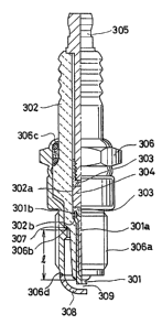
Referring to Fig. l in which a spark plug is shown,
- 4 -
'
1328587
the spark plug llas a center electrode 301 having a copper
core 301a clad by a nickel. A tubular insulator 302 has
an axial bore 302a into whicll the center electrotle 301
is place~l with a flanged hea(l 301b engage(l against u step
302b. The flanged heacl 301a sandwiches a resistor 304 by
an electrical conductor glass sealant 303 by way of a
terminal electrode 305. A metallic shell 306 llas a male
thread 306a at its outer surface. Into tlle metallic shell
306 the insulator 302 is placed with a packing 307 seated
on a step 306b. A rear part 306c of the metallic shell
306 is inturned or the purpose fixing by means of caulking.
A spark gap 309 is formed between the center electrode
301 and an outer electrode 30~ depended from an upper en(l
306d of the metnllic shell 306.
In tllis embodiment of tlle present invention the
metallic shell 306 has a tensile stress of more than 40
Kg/mm Witll u thermal conductivity oE more than 60 W/m-k.
An insulator has D witllstand voltage of more than 10 KV
and a bending strength oE more than 15 Kg/mm~ with the
thermal conductivity of more than 60 W/m.k.
Copper alloys of the metallic shell i5 selected
from specimens A - G at Table 1 while aluminum alloys
of the insulator i9 selected from specimens 11 - K at Table
2. /~mong the specimens the copper alloys A - F are found
to be sufficient Eor this invention while aluminum alloy
specimens I K are acceptable for this invention.
Ileat resistant experiment has conducted with three
,. .. ~ ~
:
1~28~87
conventional sparlc plugs (~PR51'S) cmployed to compare a
spark plug which has a metallic shell made of specimens
F, K and employed an alumina insulator.
The test is carried out by incremcntally changing
an ignition advance angle with 4-cylinder 2000cc engine
employed.
As a result, it is found that the heat rcsistance
has been improved by the angle of 2.5 - 7.5 degrees as
seen in Fig. 2.
In the meanwl1ile, among tl1e specimens I - V indicated
at Table 3, (BeO) and (AlN) are acccptable in view o~ tl1e
thermal conductivity, the withstand voltage and the bending
strength.
~` 132~87
~ ~ ~ _ o _ ., _
~ ~ ~ ~ ~ ~ ~ C~ o
C ~ ~ O ~D O O' ~_
. q> ~ e~ .~ I ~ r I ~D ~
.~ ,~, ~ .._ _ _...._
~- -. ~ ~ ~ U~ ~ ~o~ o ~'
v 3.'-` _ _ _
_~ , ~ ~ o _ ' e '~ l D ~ r~-~ ~o .
m _I c ~ ~ '~ '~ ~ l w O
~1 ~ ~0 e~l0 O _ _
¦ æ ¦ ¦ ~ 8-''1
. ~ ~ 1~ ~ c~ ~ ~
- / .._ l _ . .. ~u ' ~ ~D
/ n~ ~0 ~0 ~ n~ _ r~
. .; ` .i . .
.
.
.- ~ , : .
13~8~87
. .
T~ LE 2
. .__ . . ' . .
specimcn H SpcC i~cn I spcci~cn J speci~cn K
. I .
involved ratin~ JIS~ 1100 1114 JISA 7075 T6JISA 2024 T4 JISA 2011 T8
S i Si + fc below 0.40 0.50 0.40
F e bclow 1.0 below O.S0 0.50 0.70
. _
C u 0.05 - 0.20 1.7 - 2.D 3.8 - 4.9 5.0 - 6.0 I .
che~ical M n bclow 0.05 bclow 0.30 0.3 - 0.9
: component M ~ 2.1 - 2.9 1.2 - 1.8
_I _
(wt% ) Cr 0.1~- 0.28 0.10
Z n bclow 0.10 5.1 - 61 0.25 0.3
Zr + Tl Zr + Ti Pb 0.2 - 0.6
bclow 0.25 below 0.20 Bi 0. 2 - 0. 6
. . _ .
T i _ bclow 0.2
__ .__ .. _
A Q abovc 99.0 Bal Bal Bal
dcnslty 2. 7 2 80 2.77 2.82
: ther~al 222 130 121 171
conductlvity
. . _ _
character electrlcal 59 % 33 % 30 % 45 96
-istlcs conductlvlty
.. ... _ .. . . I
.tensilc 12.5 57.7 43.0 41.5
; stross
. . . __ _
l hardness 90 160 125 105
. .
refercnces _ agclng agclns a~olng
troat~ont I trcat~ont trcal~ont
. .___ - . . . .
j~.
.
.
.
- : .
. ~ , -
- - , . . .
1~2~87
.. ., ~ , ~ ,
l ~
C ~ ~ ~ l ~ ~ o ~
U~ ,, ~ er ~ ~ ~
. ~ ~ o _ _ l _
X X X X X
c~ _ _
L ~ ~
.__ . . .._
t .~ a~ ~ ~ ~ a~
C C~i ~ e~ C~ C~
,' --<a l _ ......... . O
~ O ¢ Z . N
._.=: _
/ ~ ~ ~ E~
/ .~ .~ .~ ~ ' .
/
~., ' ,, 1,
J
.':
,, -, I
t
^` 132~87
~ xperiment was carried out with the insulator of
specimen F assembled to the metallic shells of copper alloy
and (SlOC) steel.
Combination of the (AlN)-insulator and the copper
metallic shell has made it possible to significantly improve
the heat resistance as seen Fig. 3.
The improved heat resistance leads to lengthening
the leg elongation of the insulator from (11) to (12) as
seen in Fig. 4, and at the same time, enhancing fouling
resistance.
In this experiment, each cycle is formed by combining
factors of racing - ldling - 15 (Km/h) - 35 (Kmth) at a
room temperature of ten freezing degrees Celsius. These
cycles are repeated, so that fouling is estimated when
the engine inadvertently stops, otherwise failing to mske
the engine restart.
As another modification of this invention, a tubular
insulator 212 is made oP (BeO) and (AlN) as seen in Fig.
5. The insulator 212 is integrally sintered with platinum
(Pt) alloyed wire placed into a small hole 212c to form
A center electrode 211. The small hole 211c is provided
at a leg elongation 212a. The platinum (Pt) alloy of the
center electrode 211 is made of (Pt-Ir), (Pt-Rh) or the
like.
The cent~r electrode 211 is connected to a middle
electrode 213 and a terminal 205, and rigidly secured by
means of an electrically conductive adhesive 203. The
!
1.
-- 10 --
. ~ : ;,.,
,
: ~ .
..
~32~587
insulator 212 is combined wi~h a metallic shell 206 which
is in accordance with copper alloy and aluminum alloy as
listed at Tables 1, 2. In the spark plug having the
insulator 212 thus integrally sintered with the center
electrode 211, the heat rcsistance becomes somewhat reduced.
However, combination of the insulator 212 and the metallic
shell according to this embodiment, makes it possible to
compensate for the reduction of the heat resistance.
The insulator 212 of this type is particularly useful
for a small scale spark plug (10 mm - 8 mm in diameter
of a male screw) since it is possible to make the center
electrode 211 thin, at the same time, msking the diameter
of the insulator 212 reduced with high heat resistant
property maintained. It is noted that numerals 208 and
209, in turn, designate a ground electrode and a spark
gap.
Referring now to Figs. 6 through 10, a spark plug
body (A) according further embodlment of the invention,
has a cylindrical metallic shell 1 and an insulator 2 which
has an axial center bore 21. Into the center bore 21 of
the lnsulator 2, a center electrode 3 is concentrically
inserted. The metallic shell 1 is made of pure copper which
has a hardness of ~IRB 58 at normal temperature, and having
a hardness of llRB 15 at the temperature of 350 degrees
Celsius with an electrical conductivity oE IACS 100% (20C),
a thermal conductivity of 390 W/m.k and 35 Kg/mm' of tensile
stress resistance,
1328587
After meltin~ the copper by heat, an alumina (Al203)
powder of 0.85 weight percentage, spherical diametcr of
which is 1 micron, i9 evenly dispersed into the melted
copper to form an alumina-dispersed copper.
The alumina-dispersed copper thus made, is
manufactured by plastic working in which 60 % of all the
manufacturing process in by means of cold deforming process.
The properties of the alumina-di~persed copper is
shown in Table 4.
TABLE 4
melting point (C) 1082
specific weight 20C (g/cm') 8.78
electrical conductivity 20C IACS (%) 80
thermal conductivity 20C (W/m-k) 320
electrical resistance 20C (,uQ-cm) 13.00
thermal expansion (cm/cm/C) 20.4 X 10 6
Further, the metallic shell 1 has a threaded surface
11 at its resr end to be screwed to a cylinder head of
an internal combustion engine, and at the same time, having
a middle barrel and a rear caulking pad 16a. From a front
end of the metallic shell 1, a J-shaped ground electrode
12 is depended by means of welding to form a spark gap
with a front end of the center electrode 3. An inner
surface of the metallic shell 1 has a shoulder portion
13 on which an annular packing 17 is received. In proximity
of the caulking pad 16a, a hexagonal ring nut 14 is
j ;
- 12 -
~ . . . .
- ~ . . . . ~ . . .
-~ 132~587
provided. The caulkin~ pad is inturned to retain the tubular
insulator 2 together with a line packing 16 and an annular
talc 15. The insulator 2 is of a sintered ceramic body
of aluminum nitride (AlN) which has a thermal conductivity
of 180 W/m.k (20'C). The insulator 2 has a leg elongation
22 at its front portion, upper end of which has a tapered
surface at its outer surface, and supported by the metallic
shell 1 with the tapered surface engaged against the
shoulder portion 13 by way of the packing 17.
In the meanwhile, diameter of the center bore 21
i8 somewhat reduced at the leg elongation 22, and that
of the bore 21 i8 increased through a step portion 24 at
a portlon sQmewhat behind a tapered surface 23.
The center electrode 3 i9 made of a copper core
32 clad by heat-resistant nickel alloy 31. A rear end of
the center electrode 3 has a flanged head 33 to engage
with the step portion 24, while a front end of the center
electrode 3 meet the ground elcctrode 12 with the spark
gap interposed. The peripheral space surrounding the spark
gap comes to serve as a firing tip 34. The flanged head
33 is connected to a terminal 35 by sandwiching a resistor
36 by means of electrically conductive glass sealants 37,
38.
The metallic shell 1 thus far made of the alumina-
dlspersed copper alloy, is as follows:
(a) The alumina-dispersed copper alloy has an
electrical conductivity of IACS 80 ~ (20C), and a thermal
i.
- 13 -
. . .
`, -'''
.
~- 1328~87
conductivity of 320 W/m.lc as secn at Table 4 and at a curve
(4) in Fig. 7.
The high electrical and thermal conductivity of
copper are generally maintained.
(b) Fig. 8 shows hardness in which numersls 50,
51, 52 and 53 in turn correspond to pure copper, (CdCu),
(CrCu) and (BeCu). According the curve 4 of Fig. 8, the
alumina-dispersed copper show~ its hardness of HRB ~4.5
at normal temperature, and hardness of IIRB 80 at 800 degrees
Celsius which indicates that the hardness of the
alumina-dispersed copper has significantly improved compared
to the hardness of the pure copper (see at curve 50). In
the alumina-dispersed copper, the dispersed alumina powder
acts as a barrier of dislocation to increase
recrystallization of the pure copper, avoiding the dispersed
alumina powder from being solved in the phase of the pure
copper.
Among other metallic alloys, (BeCu) shows its
hardness of IIRB 95 below 400 degrees Celsius, howcver,
its hardness rapidly deteriorates at the temperaturc of
200 - 400 degrees Celsius.
tc) Fig, 9 Bhows relationship between percentage
of cold working and mechanical strength of the alumina-
dispersed copper alloy. In Fi8. 9, the numerals 41, 42
43 and 44 in turn represent an elongation rate (%), a
withstand ~tren~th, a hardness IIRB and a tensile stress
resistance (Kg/mm~).
i'~
- 14 -
'~ ' '. -
' .
1328~87
According to Fi~. 9 with brolcen lines 40 indicating
cold working rate as 14 percent, it is found that the higher
the percentage of cold working ~ecomes, the less the
mechanical strength deteriorates.
Fig. 10 shows a mechanical strength with the cold
working rate as 14 percent, the numerals 45, 46, 47 and
48 in turn represent an elongation rate (%), a withstand
strength, a hardness HRB and a tensile stress resistance
(Kg/mm') after releasing for one hour at high temperature.
As seen Fig. 10, it is found that good mechanical
strength is maintained in some degrees even though a
considerable are employed.
Some experiments are conducted as follows to compare
the metallic shell 1 with a counterpart metallic shell
which is made of (SlOC) steel.
Prei~nition resistance test
It is found that ignition advance angle has improved
by the angle of 5 - 7.5 degrees with 4-cylinder 2000cc
engine employed.
Fouling resistance test
Each cycle is formed by combining Pactors of racing-
idlin2 - 15 tKm/h) - 35 (Km/h) at the room temperature
ten freezing degrees Celsius with 4 cylinder 2000cc engine
employed. These cycles are repeated, 80 that fouling i9
estimated when the engine inadvertently stops, otherwise
i~ .
- 15 -
.
. . ~
: .
"
1328~87
it fails to make the engine restart.
As a result, it is found that the appropriate
ignition is ensured at the cycles in which the engine stop
or the restart failure apparently occurs at the counterpart.
It is appreciated that zirconium oxide (ZrO2), or
aluminum nitride (AlN) powder may be used instead of alumina
powder. A plurality of the ceramic powders may be dispersed
as long as the weight percentage falls within the range
from 0.3 percent to 3.0 percent. Preferably, the spherical
diameter of ceramic powder may be in less than 1 micron.
It is also noted that only the leg elongation of
the insulator may be made of aluminum nitride (AlN), and
other kinds of ceramics may be added as long as the thermal
conductivity at least remains at 60 W/m-k (0.1435 cal~
8ec D C )
Referring to Figs. 11 through 13, another embodiment
of the inventlon is described hereinafter. A spark plug
body 100 has a cylindrical metallic sl-ell 190, a main part
191 of which i9 made of aluminum alloy or copper alloy
which has a good thermal conductivity of more than 60 W/m.k.
An annular ring 192 is provided to be connected to a front
end of the metallic shell 190. The ring 192 is made of
heat-reslstant metal such as steel, stalnless steel or
niclcel alloy. An inner surPace of the metallic shell 190
has a step portion 193, while an outer surface of the ring
192 has a step portlon 194. The two step portions 193 and
194 are telescopically lnterfit each other, and rigidly
- 16 -
- . : :
1~28~87
connecte~ by means of well-known welding 195 such as laser
welding, electron-welding, TIG (tungsten inert gas welding)
. or soldering. From the annular ring 192, a J-shaped ground
electrode 196 which is made of a heat resistant nickel
alloy, is depended to form a spark plug gap with a center
electrode 150 described hereinafter.
A tubular insulator 101 lncludes a front piece lOla,
and is concentrically placed within a front portion of
the metallic shell 190. The front half piece lOla of the
insulator 101 acts as a le~ elongation, and made of aluminum
nitride tAlN) having a good thermal conductlvity of more
than 60 W/m-k. The rear half piece 120 is made of relatively
inexpensive alumina (A1203).
Ilowever, it i9 n matter of course that the rear
half piece 120 may ~e made of aluminum nitride (AlN).
In the meanwhile, a rear end of the front half piece
lOla of the insulator 101 has a concentrical projection
111 which interfit into a recess 121 provided at a front
end of the rear half piece 120 to form a ~oinc-type
insulator 130. The two pieces 120 and lOla are, as seen
in Fig. 11, inter$it ln a manner of mortise-tenon ~oint
by means of glass sealant 140 which i9 a mixture of ceramic
components such as (CaO), tBaO), tA1203), tsio2) and the
llke.
The front half piece lOla ha~ an axial center bore
115 consistin~ of a diameter-reduce hole 113 and a diameter-
increased hole 114. The rear half piece 120 has a bore
. . .
I;
- 17 -
~j I
: ` ,, ~ .
., .
'
~328~87
122 axially communicating with the diameter-increased hole
114. Into the bores 113 and 114, the center electrode 150
is concentrically inserted with its front end somewhat
extended from that of the front half piece lOla. The center
electrode 150 is made of a copper core clad by a heat-
resistant nickel alloy, and having a flanged head 151 at
its rear end.
At the assemble proccss, the center electrode 150
is inserted from the rear end of the bores 115, 122 with
the flanged head 151 received by a shoulder of the dismeter-
increased hole 114, and secured by means of a heat-resistant
inorganic adhesive 152 nt the diameter-reduced hole 113.
Into the bores 115, 122, an electrically conductive glass
saalant 160 i8 provided to sandwich a noise-suppression
resistor 161. A terminal 180 i9 inserted into the bore
122, and secured by means of thc conductive glass sealant
160.
Accordlng to the embodiment of the invention, the
annular ring 192 is welded to the metallic shell 190 by
way of the step portions 193 and 194, thus strangthening
the connection, and nvoidin~ the connection from being
oxidized.
The nickel-alloyed ground electrode 196 i9 directly
welded to the annular ring 192 which has mado of metal
similar to the ground electrode 196.
Tharefore, it becomes possible to strengthen the
we,lding connection between the ring 192 and the ground
j,
- 18 -
:
.. . .
.
- : ; : . .