Note: Descriptions are shown in the official language in which they were submitted.
1328~88
INTERNAL COMBUSTION ENGINE
BACKGROUND OF THE INVENTION
The present invention relates to an internal
combustion engine having a stiffened crankcase and a shaft
bearing structure with a built-in lubricating oil supply
system.
In some conventional internal combustion engines,
a bearing cap which supports a lower portion of a journal
for supporting a crankshaft against a crankcase is fastened
to the crankcase ~see Japanese Laid-Open Patent Publication
No. 61-104114, for example).
The engine of such a construction should have a
complex reinforcing structure to give a required degree of
rigidity to the crankcase.
Some recent internal combustion engines have
balancer shafts with balancer weights, the balancer shafts
being rotatably supported in the cylinder block
symmetrically with respect to the crankshaft. The balancer
shafts are rotated at a speed which is twice that of
rotation of the crankshaft to cancel out the inertial force
due to the reciprocating mass of engine components such as
pistons to reduce unwanted vibration. Since the balancer
shafts are rotated at the higher speed than that of
rotation of the crankshaft, the bearings of the cylinder
block in which the balancer shafts are rotatably supported
should be supplied with a large amount of lubricating oil.
- 1 - ~
7~
' '' ~ ' I '
1328 ;~8g
One known bearing structure for such balancer
shafts is disclosed in Japanese Patent Publication No. 54-
17106. According to the disclosed bearing structure,
balancer shafts are supported in a crankcase by seats, and
lubricating oil is led to bearings for the balancer shafts
through oil holes defined in the crankcase, oil holes
defined in the seats, and oil holes defined in the balancer
shafts.
The disclosed bearing structure has however been
disadvantageous in that the oil holes must be machined in
the crankcase, resulting in an increase in the cost of
manufacture. The crankcase is generally formed by casting
and hence tends to have cavities therein. Therefore, when
the oil holes are subsequently machined in the crankcase,
they may communicate with such cavities. With the oil
holes joined to the cavities, oil leakage tends to occur
during operation. $he conventional bearing structure has
thus been unreliable.
SUMMARY OF THE INVENTION
It is an object of the present invention to
provide an internal combustion engine which has a simple
and highly rigid crankcase, the crankcase being employed to
define a breather chamber for separating oil from a blowby
gas which is to be discharged out.
Another object of the present invention is to
provide an internal combustion engine having a bearing
structure which can be manufactured at a reduced cost and
-- 2 --
~, ,.
. .
1328~88
is highly reliable in operation.
According to the present invention, there is
provided an internal combustion engine comprising a
cylinder block having an array of cylinders defined
therein, a crankcase coupled to a lower end of the cylinder
block, the crankcase including an upper case integrally
formed with the cylinder block and a lower case fixed to
the upper case, the upper and lower cases jointly defining
a crank chamber therebetween, the upper and lower cases
having a plurality of journal support walls projecting from
inner wall surfaces thereof, the lower case having an open
lower end, an oil pan fixed to the open lower end of the
lower case, an air intake system coupled to the cylinders,
a crankshaft rotatably sandwiched by the journal support
walls, and a breather chamber mounted on one side of the
crankcase and defined by recesses on confronting surfaces
of the upper and lower cases, the breather chamber having
one end communicating with the crank chamber and an
opposite end communicating with the air intake system.
. According to the present invention, there is also
provided an internal combustion engine comprising an engine
body having an array of cylinders defined therein, a
bearing member fixed to the engine body, the engine body
and the bearing member upper and lower mating surfaces,
respectively, joined to each other, and a crankshaft
rotatably and at least one balancer shaft rotatably
supported between the engine body and the bearing member
-- 3
.
.. .
'"' , .
- -. ' ':
:. , .
. ~
1~28~88
parallel to each other, the engine body and the bearing
member defining substantially semicylindrical recesses
therein which jointly constitute bearings in which the
crankshaft and the balancer shaft are rotatably supported,
at least one of the upper and lower mating surfaces having
an oil groove communicating with the recesses for being
supplied with lubricating oil, the oil groove and the
recesses being formed upon casting of the engine body or
the bearing member case having the at least one of the
upper and lower mating surfaces.
According to the present invention, there is
further provided an internal combustion engine comprising a
cylinder block having an array of cylinders defined
therein, a crankcase coupled to a lower end of the cylinder
block, the crankcase including an upper case integrally
formed with the cylinder block and a lower case fixed to
the upper case, the upper and lower cases having upper and
lower mating surfaces, respectively, joined to each other,
a crankshaft rotatably supported in the crankcase, and at
least one balancer shaft rotatably supported parallel to
the crankshaft, the upper and lower cases defining
substantially semicylindrical recesses therein which
jointly constitute bearlngs in which the crankshaft and the
balancer shaft are rotatably supported, at least one of the
upper and lower mating surfaces having an oil groove
communicating with the recesses for being supplied with
lubricating oil, the oil groove and the recesses being
' `
132~88
formed upon casting of the upper or lower case having the
at least one of the upper and lower mating surfaces.
According to the present invention, there is also
provided an internal combustion engine comprising a
cylinder block having an array of cylinders defined
therein, a crankcase coupled to a lower end of the cylinder
block, the crankcase including an upper case integrally
formed with the cylinder block and a lower case fixed to
the upper case, the upper and lower cases jointly defining
a crank chamber therebetween, the upper and lower cases
having a plurality of journal support walls projecting from
inner wall surfaces thereof, the lower case having an open
lower end, a crankshaft rotatably sandwiched by the journal
support walls in the crankcase, a balancer chamber mounted
on one side of the crankcase separately from the crank
chamber and defined by recesses on confronting surfaces of
the upper and lower cases, and a balancer shaft rotatably
supported in the balancer chamber.
The above and other objects, features and
advantages of the present invention will become more
apparent from the following description when taken in
conjunction with the accompanying drawings in which a
preferred embodiment o the present invention is shown by
way of illustrative example.
BRIEF DESCRIPTION OF THE DRAWINGS
FIG. 1 is a cross-sectional view of an engine
according to the present invention, taken along line I - I
. . ' : . .
.
. , , :, ~ : .
~. ~ . . . .
- 1328~8~
o FIG. 2;
FI~. 2 19 a cros~-~ectlonal vlew taken along llne
II o~ PIG. lS
PIG. 3 1~ a cross-~ectlonal vlew tuken along llne
III - III oE FIG.2:
FIG, 4 ls a cross-sectlonal vlew taken along line
IV - IV o~ PIG. 2;
FIG. S is a cross-sectlonal vlew taken along line
V - V oE FIG. ls
FIG. 6 18 an enlarged fragmentary cro~s-sectlonal
vlew of a bearlng structure ln the englne~ and
; FIG. 7 ls a cross-sectlonal vlew taken along line
VII - VII oE FIG. 6.
DEscnIp~rIoN OF TIIE Pl~EFEnnED ~MDoDI~t~N~r
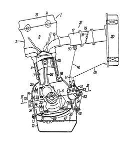
~ 8 ~hown ln FIGS. 1 and 2, an englne 1 1~ an
lnllne multlcyllnder englne llavlng an englne body
comprl~lng a cyllnder block 4 havlllg All array oE cyllnder~
3, an upper ca~e 5 lntegrally coupled to tlle lower end oE
the cyllnder block 4 tthe cyllndur block 4 and tl-e upper
ca~e 5 serve ~s an englne body), a lower ca~e ~bcarlng
Inember) ~ EAstened to the lower end oE the upper ca~e 5 by
mean~ o~ bolt~ 6 and deelnlng a crank chamber 7 between
lt~el~ and the the upper cane 5, and n cyllnder block 9
Ea~tened to the upper end oE the cyllnderblock 4 by llle~118
oE bolt~.
~ rhe upper cA~e 5 and tlle lower cA~e B ~olntly
constltute a crallkca~e 10 havltlg ~n open lower end ~o whicl
G -
.
~ ~A
: . ,
, . .. . . . . . .
. ~ . .
: ~ :
1328~88
an oil pan 12 for storing lubricating oil 11 is fastened by
means of bolts 13.
A head cover lS is joined to the upper end of the
cylinder head 9 by means of bolts in covering relation to a
valve operating device 14 disposed in the cylinder head 9.
An intake manifold 17 for distributing intake air into
intake ports 16 communicating with the respective cylinders
3 is mounted on one side surface of the cylinder head 9.
The intake manifold 17 has an inlet coupled to a throttle
body or housing 19 which houses a throttle valve 18. The
throttle body 19 has an inlet coupled to an air cleaner 20
for supplying cleaned air into the throttle body 19. The
intake manifold 17, the throttle body 19, and the air
cleaner 20 jointly serve as an air intake system 21 for the
engine 1.
A crankshaft 22 housed in the crankcase 10 is
rotatably sandwiched between a plurality of upper and lower
journal support walls 23, 24 projecting as partitions from
the inner wall surfaces of the upper and lower cases 5, 8
and spaced along the crankshaft 22. The crankshaft 22 is
operatively coupled to pistons 25 slidably fitted in the
respective cylinders 3 by means of connecting rods 26,
respectively.
To the lower ends of the journal support walls 24
of the lower case 8, there is connected a baffle plate 27
by means of bolts 28 for isolating the crankshaft 22 from
the surface of the lubricating oil in the oil pan 12. The
;,
, 7 --
:..
..
,, , :~ .,
. .
`.':, , ' `' ~ .'
~ ~ ' . . .
- .
1328~88
baffle plate 27 serves to prevent the crankshaft 22 from
being touched by the surface of the lubricating oil which
may be roughened or made turbulent when the engine is
caused to vibrate. Therefore, any resistance to rotation
of the crankshaft 22, which would otherwise be applied by
the lubricating oil, is eliminated.
The baffle plate 27 is curved so as to be convex
downwardly along the arcuate path of a maximum-diameter
portion of the crankshaft 22. The baffle plate 27 has
small hole 29 defined in its lowest portion. The
lubricating oil 11 in the oil pan 12 is supplied to the
crankshaft 22 and other engine parts by means of an oil
pump ~not shown), and then flows onto the baffle plate 27
from which the oil is discharged through the small hole 29
into the oil pan 12. Therefore, no oil remains pooled on
the baffle plate 27.
As illustrated in FIGS. 2 and 3, the crankcase 10
has a pair of balancer chambers 30 defined in its opposite
sides and extending longitudinally therealong. The
balancer chambers 30 are in the form of recesses 31, 32 on
the confronting surfaces of the upper and lower cases 5, 8.
The balancer chambers 30 house therein a pair of balancer
shafts 33, respectively, extending parallel to the
crankshaft 22 and rotatably supported by bearing walls 34,
35 projecting from inner wall surfaces of the balancer
chambers 30.
Each of the balancer shafts 33 has an end
., .
) - 8 -
:`
' ' :- ' ~ ,
.'~ . .
' ~ :
~ 132~
projecting out of one end of the balancer chamber 30 and the other
end terminating in the balancer chamber 30 at a central portion of
the crankcase 22 in its longitudinal direction. The balancer
shaft 33 has a pair of axially spaced balancer weights 33a dis-
posed on the other end thereof in sandwiching relation to one pair
of bearing walls 34,35.
The projecting ends of the balancer shafts 33 are
operatively coupled to the crankshaft 22 by means of a timing
transmission device 36.
As shown in Figure 2, the timing transmission device
36 comprises a toothed driver pulley 37 fixed to the crankshaft
22, a toothed driven pulley 38 fixed to the lefthand (as viewed
in Figure 2) balancer shaft 33, a toothed driven pully 40 fixed
to an intermediate shaft 39 rotatably supported on the crankcase
10 adjacent and parallel to the righthand balancer shaft 33, a
timing belt 41 trained around the pulleys 37, 38, 40, a driver
gear 42 fixed to the intermediate shaft 39 adjacent to the driven
pulley 40, and a driven gear 43 fixed to the righthand balancer
shaft 33 and held in mesh with the driver gear 42. The number
of teeth of each of the driven pulleys 38, 40 is half that of
teeth of the driver pulley 37, and the gears 42, 43 have the same
number of teeth. When the crankshaft 22 rotates, the balancer
shafts33 are rotated in mutually opposite direction at a speed
which is twice the speed of rotation of the crankshaft 22. The
secondary
, . .. .
132~588
inertial force of the reciprocating mass of components such
as the pistons 25 of the engine 1 is cancelled out by
combined centrifugal forces of the weights 33a.
As shown in FIG. 3, each of the balancer chambers
30 has a small hole 44 defined in a bottom wall thereof to
provide communication between the interior space of the
balancer chamber 30 and the space in the oil pan 12 outside
of the baffle plate 27.
As illustrated in FIGS. 1, 2, and 5, a breather
chamber 45 is defined in one side of the crankcase 22
adjacent to one (the righthand one in FIG . 2) of the
balancer chambers 30 in the longitudinal direction of the
crankcase 22. The breather chamber 45 is defined by
recesses 51, 52 on the confronting surfaces of the upper
and lower cases 5, 8.
The breather chamber 4S is held in communication
with a space 47 between the baffle plate 27 and the surface
of the oil in the oil pan 12 through an inlet hole 46
defined in the bottom wall of the breather chamber 45 at
one end thereof. The breather chamber 4S is also held in
communication with upstream portions of the intake manifold
17 and the air cleaner 20 through first and second outlet
pipes 48, 49 connected to the breather chamber 45 on its
upper wall at the other end thereof. The first outlet pipe
4a has a known pressure regulating valve 50.
The breather chamber 45 has its inner space
shaped as a labyrinth by a plurality of staggered walls 53,
, -- 1 0
.
: ~ !
,
:
~328~
,,
54 projecting inwardly from the inner wall surfaces of the
recesses 51, S2, the labyrinth extending between the
opposite ends of the breather chamber 45. The lower case 8
has a plurality of longitudinally spaced small holes 55
defined therein to provide communication between the
~ labyrinth and the space 47.
: As shown in FIG. 4, the lubricating oil pumped
from the oil pan 12 is fed under pressure to a hollow space
in the crankshaft 22 through a main oil passage or gallery
58 defined in the cylinder block 5 and oil passages 57
extending radially inwardly from the main oil passage.58
toward oil grooves 56 defined in the inner peripheral
surfaces of the central and outer journal support walls
23. From the oil grooves 56, the lubricating oil is
supplied to the journals and crankpins of the crankshaft
22. ~he lubricating oil in the main oil passage 58 is also
supplied to the valve operating device 14 through an oil
passage ~not shown).
A portion of the oil flowing through the oil
passages 56 is supplied to the inner peripheral surfaces of
the bearing wall~ 34, 35 of the balancer chambers 30
through oil grooves 59 defined in the upper mating surfaces
of the lower journal support walls 24~
More specifically, as shown in FIG. 4, the upper
case 5 has a lower mating surface 60 and the lower case 8
has an upper mating surface 64, the lower and upper mating
surfaces 60, 64 being held in mating engagement with each
- 1 1 -
. .
~f
" ' ~ `, ' ~ ': ".
.. ..
"' ' ' . :
--` 1328~88
other. The lower mating surface 60 has deined therein semi-
cylindrical recesses 61, 62, 63 opening downwardly, the oil grooves
56 being defined by the semicylindrical recesses 61. The upper
mating surface 64 has defined therein semicylindrical recesses
65, 66, 67 opening upwardly in registry with the recesses 61, 62,
63, respectively. When the mating surfaces 60, 64 are held against
each other, the semicylindrical recesses 61, 62, 63 and the semi-
circular recesses 65, 66, 67 jointly define substantially cylindri-
cal bearings 68, 69, 70, respectively, in which the crankshaft
10 22 and the balancer shafts 33 are rotatably supported. As shown
in Figures 4, 6 and 7, oil grooves 59 are defined in the upper
mating surfaces 64 communicate with arcuate oil grooves 71, 72,
respectively, are defined in the peripheral surfaces of the recesses
66, 67, respectively. The oil grooves 59 thus have end~ communi-
cating with the oil grooves 56 and opposite ends wlth the oil
grooves 71, 72. The oil grooves 59, the recesses 61, 62, 63, 65,
66, 67, and the oil grooves 71, 72 are defined at the same time
that the upper and lower cases 5, 8 are cast.
While the engine is in operation, blowby gases pro-
20 duced in the cran~ chamber 7 10w into the space 27 below the
baffle plate 27 and then flow along the lower surface of the baffle
plate 27 into the breather chamber 45 through the inlet hole 46.
As the blowby gases flow through the labyrinth space inthe breather
chamber 45, oil is separated rom the blowby gase~, and the blowby
gases are then supplied
-12-
~,. A
.
.... - .
- ' ~ .
132~8~)'
via the first and second outlet pipes 48, 49 into the air
intake system 21 for recombustion in the cylinders 3.
The oil separated from the blowby gases in the
breather chamber 45 flows down via the inlet hole 46 and
the small holes 55 back into the oil pan 12. No matter how
the engine 1 may be tilted at this time, the oil returning
from the breather chamber 45 into the oil pan 12 is
prevented from touching the crankshaft 22 by the baffle
plate 27. Therefore, tho oil does not impose any
resistance to the rotation of the crankshaft 22.
Lubricating oil having lubricated the balancer
shafts 33 returns from the balancer chambers 30 through the
small holes 44 into the oil pan 12. This oil is also_
prevented from touching the crankshaft 22 by the baffle
plate 27.
Lubricating oil which has lubricated the
crankshaft 22 and been scattered around the crankshaft 22
is prevented by the baffle plate 27 from entering the inlet
hole 46 and the small holes 55 of the breather chamber 45.
The journal support walls 23, 24 disposed in the
upper and lower cases 5, 8 for supporting the crankshaft 22
greatly contribute to an increased degree of rigidity of
the crankcage 10.
Since the breather chamber 45 is composed of the
recesses 51, 52 defined by the confronting surfaces of the
upper and lower cases 5, 8, no special box or casing would
be required to define the breather chamber 45. The
- 13 -
,
, .
. . ~
, ' ` ' ~
.
1328~88
crankcase 10 is further stiffened by the peripheral wall ofthe breather chamber 45 and also the peripheral walls of
the balancer chambers 30.
Lubricating oil supplied to the oil grooves 56
lubricates the journals of the crankshaft 22, and is then
partly supplied to the oil grooves 59, from which the oil
is led into the oil grooves 71, 72 to lubricate the
bearings 69, 70 for the balancer shafts 33. Then, the
lubricating oil is discharged into the oil pan 12 through
discharge passages (not shown). While the engine 1 is not
in operation, lubricating oil remains trapped in the oil
grooves 59, 71, 72. Therefore, when the engine 1 is
subsequently started, the bearings 68, 69, 70 are well
lubricated by the trapped lubricating oil even if the
supply of lubricating oil from the oil pump is delayed, and
hence the engine 1 can smoothly be started.
Since the oil grooves S9, the recesses 61, 62,
63, 65, 66, 67, and the oil grooves 71, 72 are defined at
the same time that the upper and lower cases 5, 8 are cast,
no subsequent machining i8 required to define these
recesses and oil grooves, and no lubricating oil would leak
from the recesses and oil grooves through cavitie5 in the
cast upper and lower cases 5, 8. Therefore, the
lubricating system is highly reliable in operation.
Although a certain preferred embodiment has been
shown and described, it should be understood that many
changes and modifications may be made therein without
departing from the scope of the appended claims.
- 14 -