Note: Descriptions are shown in the official language in which they were submitted.
:` -
. 132q'16
~ PLASMA THIN FILM DEPOSITION PROCESS CONTROL
, ~
Background of the Invention
This invention relates generally to plasma
diagnostics and process control in depositing thin films
on substrates, particularly ~hose processes utilizing
sputtering, plasma enhanced chemical vapor deposition
(PECVD) and plasma polymerization.
As is well known, a thin film depositing plasma
is formed in a chamber by introducing at least one gas
into a region of a controlled electrical field. Many
such plasma processes operate at low pressure with
magnetic confinement. Most plasma processes involve a
control of at least the internal pressure level, the
electrical field characteristics, and the composition and
proportional flow rates of individual gases into the
plasma. Selection of these variables, in turn, affects
the properties of a resulting thin film. Such properties
can include the film's hardness, its adhesion to the
substrate, its permeability to certain liquids or gases,
optical characteristics of translucence and refractive
index, and its general composition. The property or
properties of the resulting film that are important
depend upon the purpose and application of the resulting
product. For example, if a scratch resistant coating is
being applied to glass, the film's hardness, adhesion to
glass and degree of optical clarity are the most important
properties. In another example, wherein a coating is
desired to prevent the permeation of oxygen, that
property of the thin film is most important~
It is, of course, desired to control the plasma
variables in order to produce a product with the desired
film properties. ~eretofore, most process control has
,,
''
, . .
.
' ' ~ `;
1 32~ 1 6~
~ 2
. .
been manual, based upon some but incomplete measurement
of the resulting plasma characteristics. One such tech-
nique is to measure the electron temperature (T ) of the
plasma, which is a measure of the average electron energy
in the plasma, by the use of available Langmuir ~electro-
static) probe(s) positioned in the plasma. The plasma
variables are then manually adjusted until the average
,~
electron temperature corresponds to that which has been
determined to be necessary for obtaining the desired film
.
, properties or rate of deposition of the film on the
- substrate. However, since the Langmuir probe(s) must be
; positioned in the plasma, they quickly become coated with
the film being deposited and its readings then are subject
to considerable error. Also, such an average electron
temperature measurement provides only a partial picture
't,' of the plasma's characteristics which, in some thin film
processes, is inadequate.
It is still the practice in large-scale commer-
.,
cial thin film deposition processes to adjust the plasma
variables to a combination that is believed by the
operator to be optimum for a particular application, and
then to run and test a sample. Only when the plasma
variables have been readjusted in response to many such
test cycles is the plasma process adjusted for commercial
runs.
Therefore, it is a primary object of the
present invention to provide improved monitoring and
control of the plasma process in order to provide a higher
yield of coated product having films with uniform and
repeatable properties.
It is another ob]ect of the present invention
to provide a plasma thin film deposition process that is
suitable for continuous commercial use in the coating of
large substrates such as automobile and architectural
glass.
., .
.
'' ` - ~ ~ ' , " '
:
132ql~
,.~
Summary of the Invention
These and additional objects are accomplished
by the various aspects of the present invention wherein,
briefly and generally, characteristics of the emission of
electromagnetic radiation in the visible and near visible
regions of the plasma are moni~ored, such as by use of a
spectrometer, and input variables to the plasma process
are controlled in response to this moni~oring. The
purpose of this monitoring and control is to maintain the
monitored aspects of the plasma emission at a level that
has been determined to relate to certain desired proper-
ties of the thin film that is being deposited. Such
properties may be resistance to scratching or optical
clarity of the film, as examples. Certain aspects of the
plasma emission found to correlate with a high film
deposition rate can also be controlled. These plasma
characteristics are controlled in real time by automa-
tically making any adiustments to the plasma input
variables that are necessary to maintain the monitored
plas~a emission characteristics within close limits.
This results in the thin film coating being uniform and
the process being repeatable. The necessity for inde-
pendent test depositions and subsequent analysis of the
film properties is minimized. A high yield process for
commercially coating large substrates is made practical
by this diagnostic and control technique.
According to a particular aspect of the present
invention, described in detail hereinafter, the intensity
of each of a plurality of lines of emission of the plasma
is measured and compared. It has been found that the
average electron temperature (T ) in the plasma is
proportional to a ratio of the intensities of two lines of
emissions from a single species in the plasma. Since
' .
;
,
. ~; . :: ' . .
. , ~'~ ~ '.'
1 32~ 1 6
.
,: .
such a species has been excited to emission by absorbing
energy from colliding electrons, the intensity of the
lines is proportional to such an average energy. By
comparing emission line intensities, the distribution of
those energies can be estimated and T calculated. The
average electron temperature of the plasma af~ects the
film deposition rate and properties of the resul~ing
film, so it is an important piece of information to have
in a real time plasma control system. As an alternative
to calculating the average electron temperature, the
ratio of intensities of the emission lines in the single
species may be controlled directly by adjusting the
plasma input variables until a predetermined value of the
ratio is obtained, the predetermined value having been
earlier determined to provide a film having the desired
properties.
By taking another ratio of two emission lines,
one produced by a species that necessarily absorbs a high
energy from electron collisions with it and another from a
species having a probability of having absorbed much
lower energy from electron collisions with it to give the
measured emission, a declining "tail" of an electron
energy (temperature) distribution within the plasma can
be monitored and controlled. It has been found that high
energy electrons in the plasma can inadvertently be
suppressed in the course of optimizing other variables.
Thereforep a separate high energy electron density
measurement reveals whether this is happening or not and
allows an adjustment to be made in real time to maintain a
sufficient proportion of high energy electrons in the
plasma. An adequate supply of high energy electrons is
important to the hardness of the resulting film.
,.
~, ~ . .",
, ~ :
:
!
1 3 2 q 1 6 6
: `:
,.~
Additional objects, advantages and features of
the various aspects of the present invention will ~ecome
apparent from the following description of its preferred
embodiments, such description being given in conjunction
. with the accompanying drawings.
. Brief Descri~tion of the Drawings
'~ Figure 1 is a general schematic diagram illus-
~ trating a plasma system utilizing the various aspects of
`. the present invention;
. Figure 2 schematically illustrates a side
~ sectional view of the plasma deposition chamber and its
,` associated equipment;
Figure 3 is an example spectrum of the emission
of plasma;
Figures 4A, 4B and 4C illustrate the bonding of
components of a molecule of a gas used in an example
plasma enhanced chemical vapor deposition process;
Figure 5 includes a series of curves that
illustrate the electron energy distribution in an example
plasma;
Figure 6 is an example energy level diagram for
a single species in a plasma;
Figure 7 is a flow diagram for a computer
program that controls plasma process input variables in
response to the measured plasma spectra;
Figure 8 shows additional elements added to the
plasma system of Figs. 1 and 2
Figure 9 is a partial sectional view of Fig. 8,
i taken at section 9-9 thereof; and
Figure 10 illustrates one aspect of the opera-
tion of the elements shown in Figs. 8 and 9.
- . ' ' ~. . ':
' ' '. ~
.
1 329 1 6~
~ 6
.~
Description of the Preferred Embodiments
General System
,
Referring initially to Figure 1, a system is
schematically illustrated that includes an enclosed
reac~ion chamber 11 in which a plasma is formed and in
which a substrate, such as substrate 13, is placed for
depositing a thin film of material on it. The substrate
13 can be any vacuum compatible material, such as metal,
glass, some plastics and coated substrates. One or more
gases are supplied to the reaction chamber by a gas supply
system 15. An electric field is created by a power supply
17, and a low pressure is maintained by a pressure control
system 19. An optical emission spectrometer 21 is
connected through an optical fiber light transmission
medium 23 to the reaction chamber in some appropriate
manner to couple the visible and near visible emission
(especially the ultraviolet wavelengths) of the plasma to
the spectrometer. A quartz window 24 in a side wall of
the reaction chamber can be used to optically couple the
plasma emission with the external fiber medium 23.
general system control 25, including a computer control
portion, is connected to each of the other components of
the system in a manner to receive status information from
them and send controlling commands to them.
The reaction chamber 11 can, in the system of
Figure 1, be of an appropriate type to perform any of the
sputtering, plasma~enhanced chemical vapor depo$ition
(PECVD), plasma polymerization processes or other vacuum
thin film deposition processes. A more detailed explana
tion of certain components of the system of Figure 1 is
given with respect to Figure 2, an example of the PECVD or
, ~
plasma polymerization process being given. The reaction
chamber 11 is divided into a load lock compartment 27 and
:`
. .
'. ' 1,
; . ~......... . .
. ' '" ~ ~ ' , . . .
.,: '
;.-.
1 329 1 ~
~ 7
,
,
a process compartment 29 by an isolation slit valve 31.
The pressure control system 19 includes a mechanical pump
,.
33 connected to the load lock chamber 27 by a valve 35.
The pressure control system also includes diffusion pumps
37 and 39, and an associated mechanical pump 41. The
diffusion pump 37 is connected to the load lock chamber 27
through an isolation gate valve 43 and an adjustable
baffle 45. Similarly, the diffusion pump 39 is connected
to the process chamber 29 through an isolation gate valve
47 and an adjustable baffle 49. The baffle 49 is
.,
controlled by the system control 25, while a coating
process is being carried out, in order to maintain the
internal pressure at a desired value.
A substrate to be coated is first loaded into
the load lock compartment 27 with the valve 31 closed.
The mechanical pump 33 then reduces the pressure most of
the way to the high vacuum region. The diffusion pu~p 37
~:! iS then operated to reduce the pressure further, to about
5 x 10 Torr. The operating pressure is typically in the
neighborhood of 46 microns for a PECVD or plasma
polymerization process and is achieved by flowing the
process gases into the reaction chamber and throttling
i the diffusion pump 39 by use of the baffle 49. During
'! loading and unloading operations, the diffusion pump 39
maintains the deposition chamber 29 at the operating
pressure. Once the load lock chamber 27 is reduced to
` base pressure, the valve 31 is opened and the substrate 13
moved into the deposition chamber 29.
~ Provision is made for moving the substrate 13
-~ back and forth through a region 51 where a plasma is
~i formed. In the example system being described, this is
-' accomplished by a plurality of rollers 53, preferably
made of aluminium with substrate supporting, electrically
,' '. ' .
`~
~ 1 3291 6~
:~'
,~
insulative O-ring spacers attached around outside sur-
faces. The rollers are driven by a motor source ~not
shown) to rotate about their axes at controllable speeds
and thus move the substrate 13. A typical deposition
process involves passing the substrate 13 back and forth
through the plasma 51 a number of times in order that the
thin film deposited on the top of the substrate 13 has a
desired uniform thickness.
A magnetron is positioned within the chamber
29, formed of a magnetic structure 55 and a cathode 57.
The power supply 17 has its output connected between the
cathode 57 and a metallic body of the reaction chamber 29.
The magnetron creates an appropriate combination of
magnetic and electrical fields in the region 51 in order
to create a plasma there when the proper gases are
introduced into the reaction chamber 29. The substrate
13 is maintained electrically isolated and is passed
directly through the plasma region 51.
The gaseous components necessary for the plasma
to form in the region 51 are introduced into the
deposition chamber 29 by a conduit 59. A tube (not shown)
having a plurality of gas supply nozzles along its length
is positioned across the width of the chamber 29 (in a
direction into the paper of Figure 2) at the position
where the conduit 59 enters the chamber. That gas flows
within the deposition chamber 29 generally from the
supply tube to the diffusion pump 3~, as shown in dotted
outline in Figure 2. It has been found preferable to
introduce the gas on the side of the plasma region 51 that
is closest to the pump 39. A pair of baffles 61 and 63 on
either side of the magnetron also helps to confine the gas
flow to the plasma region 51.
,1 .
~,
.~
, 1 .
,:;. ~ ' "
, . . .
~ .
,~ :
,, : .
.. ..
.,
i 132~16~
g
.,
A particular gas supply system 15 that is
connected to the conduit 59 depends, of course, on how
many gases are being combined and their nature. In the
example of Figure 2, two separate sources 65 and 67 of
gases under high pressure are utilizedr fewer or addi-
tional such gas sources being necessary for other
processes. Also, in this particular example, a source 69
of a liquid material to be vaporized is provided. A
vaporizing apparatus 71 provides a desired controlled
flow of vapor into the input condui~ 59, in accordance
with a control signal from the system control 25 that
operates upon a flow meter that is part of the apparatus
71. Similarly, the high pressure gases 65 and 67 are
delivered through individually controlled flow meters 73
and 75, respectively. An important control of the plasma
51, and thus of the resulting film deposited on the
substrate 13, is provided by the ability to adjust the
proportions of each gaseous component that is flowing
through the inlet tube 59 and into the deposition chamber
29. Each of the flow meters 73 and 75, and that in the
apparatus 71, supply the system control 25 with an
electrical signal proportional to the flow rate of gas
through it, and also responds to a signal from the system
control 25 to adjust and control that flow rate.
In some applications, particularly in large-
scale commercial plasma coating systems, steps are
desirably taken to assure a sufficient supply of ! gases
from the supply system 15. In a commercial coater, it is
desired that the highest possible deposition rate be
achieved without degrading the quality of the deposited
thin film. In order to assure that the deposition rate is
not limited by the amount of gas that is made available
within the reaction chamber 29, the gas supply system 15
.
:'
i' , ~ , .
'1,: . : , . : '
~. .. . ' '.
i : '
1 329 1 6.',
and pressure control system 19 need to be adequately
sized.
The pressure control system 19 needs to have
its mechanical pump 41 and dif~usion pump 39 large enough
to enable a flow of gases through the reaction chamber 11
sufficient that enough unreacted gas is always available
in it. Alternatively, additional such pumps can be added
to provide such a flow. To increase the effect of the
pump shown in Fig. 2, the baffle 49 at the inlet of the
diffusion pump 39 can be removed entirely, thereby
causing the diffusion pump 39 to operate unimpeded. The
diffusion pump 39 can even be eliminated en~irely, and a
larger mechanical pump 41 provided, as another alter-
native to providing the ability to reduce the pressure
within the reaction chamber 290
Of course, in order to take advantage of a given
large pumping capability in the pressure control system
19, the gas supply system 15 must be adequately sized.
The balance between the pumping ability and source gas
supply is chosen to result in the desired operating
pressure within the chamber 29, and to assure that the
thin film deposition process is not limited in any way by
a lack of supply of a reactant gas component. The
provision of a plurality of gas inlets to the reaction
chamber 11 also allows an increased gas flow rate, as well
as a good distribution of fresh gas thoughout the chamber.
....
~ Plasma Diagnostics and Control
~.,
A primary goal of the system and procedures to
be described in this section is to adapt the system
described with respect to Figures 1 and 2 for use in a
; continuous, commercially feasible process that repeat-
~, ably produces thin films having uniform characteristics.
~i
i
. . .
'i '
. .
1 329 1 66
11
;`~
., ~
A specific example of such a system is described with
respect to Figures 3-7 herein. In this illustrative
example, the liquid 69 is an organosilicon, and the
pressurized gases 65 and 67 are oxygen and helium,
respectively. The particular organosilicon chosen for
illustration is hexamethyldisiloxane (~MDSO), its struc-
ture being illustrated in Figure 4A. The result of this
example PECVD process is a thin film that is very hard,
scratch resistant, optically clear and adheres well to
substrates. Useful applications of this particular thin
film include the coating of automobile or architectural
glass substrates, either directly on the glass or on top
of one or more other thin films such as a sputter
deposited low emissivity coating. As will be recognized,
this class of substrates is physically large so the
process must be able to form a film having uniform
characteristics over the entire surface area of each
item. However, the diagnoses and control techniques
about to be described with respect to such an example have
a wide and general application to numerous other specific
. .
plasma processes and starting gaseous materials in thin
film deposition processes.
Figure 3 is an example optical emission spec-
~;
trum obtained by the spectrometer 21 of Figure 1 from a
` plasma formed in the process chamber 29 from such a
combination of gases. The intensities of three strong
emission lines are measured and used to diagno$e the
characteristic of the plasma and then to make any
adiustments to the relative proportion of the gaseous
constituents that are required to maintain the plasma in a
desired condition. These lines are the hydrogen alpha
line 81, at about 657.1 nanometers wavelength, the
hydrogen beta line B8, at about 486.1 nanometers wave-
~ . ' , ~ .
:' .
~ - \
1 329 1 66
12
length, and a helium emission line 85, at about 501.8
nanometers wavelenqth. Since these three emission peaks
are very strong relative to the intensity of the
surrounding portion of the spectra, and are very narrow in
bandwidth, the spectrometer 21 need have a resolution
capability of only 0.5 nanometers, which is well within
the resolving power of commercially available instru-
ments.
In order to eliminate the effects of unknown
variables and undesired optical signal noise, ratios of
these intensity levels are utilized to diagnose the
plasma and control the process. In this example, the
ratio of the intensity of the hydrogen alpha line 81 to
the intensity of the helium line 85 is used to control the
rate of flow of the silicon source material vapor through
the flow meter 71. This material is the source of
hydrogen whose emission is being monitored. When that
ratio exceeds a reference value, the computer control
system 25 causes the flow meter within the apparatus 71 to
decrease the rate of flow of the silicon material vapor,
without affecting the flow rates of the other ga~es.
Also, if that ratio falls below the reference value, the
flow meter 71 is opened to increase the flow of the
silicon source material vapor.
A second ratio that is utilized is of the
intensities of two emission lines of a single atomic or
molecular species in the plasma. In this specific
example, the intensities of the hydrogen alpha line 81 and
the hydrogen beta line 83 are used. As explained below,
this ratio is proportional to the average electron energy
(average electron temperature T ) of the plasma. If this
ratio, or the T calculated from it, exceeds a reference
v=lue, the computer control 25 caoses the flow meter 73 to
,
, ~ :
.
~:
f~
1 329 1 ~16
; 13
increase the flow of oxygen without affecting the rate of
~; flow of the silicon source vapor or helium. If the
` intensity ratio, or the T calculated from it, falls below
a reference value, the rate of oxygen flow is caused to
decrease. A higher proportion of oxygen is believed to
cause the average electron energy to decrease by combina-
tion with atomic hydroqen which is a primary source of
electrons in this gaseous mixture.
The nature of our example plasma will now be
explored, and the relationship of the emission line
intensity ratios to it will be explained. Figure 4A
illustrates a molecule of the silicon source vapor. It
is desired that the portion Si-O-Si be deposited on the
substrate. As noted in Figure 4A, the bond energy
between the silicon and oxygen atoms is significantly
higher than that of the other bonds in the molecule. That
bond strength is 8.31 electron volts (eV). The bond
energy between the silicon atom and the methyl group CH3
is 4.53 electron volts. Figure 4B shows the methyl group
with a carbon~hydrogen bond energy of 3.51 electron
- volts. Therefore, in a plasma having a distribution of
high energy electrons colliding wi~h the silicon source
molecules, there is a high probability that a collision of
an electron with the molecule will cause a methyl group or
hydrogen to be fractured away from the rest of the
molecule without affecting the Si-O-Si component. The
oxygen introduced into the plasma is believed to combine
with the hydrogen and the carbon to form various gas and
vapor compounds that are exhausted out of the deposition
chamber 29 through the diffusion pump 39. This is
another benefit of the oxygen component of the plasma gas.
In this example, it is desired to minimize, or completely
eliminate, any carbon from the deposited film. An
inorganic thin film is the goal.
',
.,
~,
, ; ~, :
.:.` ' ; -
.
~:
` -`` I 329 1 66
14
A theoretical Maxwellian distribution of the
energies of a population of electrons in the pl~sma is
given in Figure 5. A solid curve 87 shows one such
distribution. The electron population represented by
curve 87 has an average energy T . When the population of
electrons have a higher energy, the distribution of
energies shifts, such as shown by the dotted curve 89, but
retains its basic shape. Similarly, if the overall
energy of a population of electrons decreases, the curve
shifts to a lower position, such as indicated by the
alternate curve 91.
It can be seen from Figure 5 that the proper
position for the electron energy distribution curve is
where the density of electrons with energy sufficient to
break the Si-C bond is much greater than the density of
electrons having an energy great enough to undesirably
break the Si-O bond. It can be seen from the shape of the
curves of Figure 5 that this does indeed occur, keeping in
mind that the vertical electron density scale is a
logarithmic one. Indeed, it has been found that the
distribution represented by the solid line 87 is approxi-
mately optimum in the example being described, a T of
slightly over 1.0 being desired.
It will also be noted from Figure 5 that the
three emission lines discussed with respect to Figure 3
are also represented. The excitation energy that results
in the hydrogen alpha line 93 is positioned at about 12
electron volts, that for the hydrogen beta line 95 at
about 12~7 electron volts, and that for the helium line 97
at about 23 electron volts. These energies represent
that which the hydrogen or helium atom must absorb from a
collision with a free electron in order to emit the
monitored wavelength of radiation when the a~om relaxes
from its excited state.
,
,~ .
1329~6
'
, . .
Figure 6 shows an energy diagram from the
hydrogen ato~ that illustrates this. A collision with an
electron of more than 12.07 electron volts can cause the
atom to become excited with its electron being moved from
a ground energy quantum level n=l ~o a higher energy
quantum level n=3. When that excited electron falls to
the next lower energy ~uantum level n=2, a hydrogen
alpha wavelength photon is emitted. Similarly, a hydro-
gen beta wavelength photon is emitted when an excited
hydrogen atom having collided with an electron of energy
greater than 12.73 electron volts relaxes from its
excited n=4 quantum energy level back to the n=2 energy
quantum level. As a result, the intensities of these
hydrogen emission lines is related to the density of
electrons in the plasma having those energy levels~ The
ratio of the intensities of these hydrogen emission lines
then provides a ratio of those densities. This allows a
Maxwellian electron density curve to effectively be fit
to those two points~ from which the average electron
temperature T may be determined.
e
However, the high energy "tail" of the electron
energy curve of Figure 5 is desirably separately mea-
sured. The hydrogen line intensity ratio is suitable for
defining the rest of the curve since the electron
densities represented by it are at energy levels in the
main part of the energy distribution curve. But the
density distribution at higher energy levels can at the
same time drop off to very low levels. This is believed
due to ineffective energy coupling. Therefore, a separ-
ate measurement at a high energy level is also performed.
In this example, a helium line of emission is chosen, and
:,
~'~ that is ratioed with one of the hydrogen lines, preferably
the hydrogen alpha line, as a reference. This desired
,. ;i~
, i
' ~.1
' 5
~''
:, ' ,
~`' ,, ` '
:
'
: ~ :
;''~
29 1 6~
~ 16
:
- ratio is determined in advance of a deposition process,
with the measured ratio being compared to that standard
and any adjustment~ necessary being made in real time.
A quantity of high energy electrons, repre-
sented by the "tail" of the curve of Figure 5, is
generally desirable for directly impinging upon the
substrate since it is known that this improves the
hardness of the resulting deposited film through a higher
degree of film cross-linking. Stress in the film also
decreases, resulting in better adhesion of the film to the
substrate. A low ratio in the plasma emission of the
~ hydrogen alpha line intensity to that of helium predicts
; these beneficial results.
Use of the helium emission line in forming this
second ratio is also advantageous since helium is inert.
il The gas does not combine with other gas components of the
plasma. Any inert gas has this advantage, as well as
providing an emission line in the "tail" portion of the
curve. An inert gas is used in this example primarily for
facilitating an initial source of electrons when the
plasma is initiated by establishing the electric field.
~'~i But it has this additional diagnostic use, as well.
Once it is determined from the measured inten-
sities and ratios that the electron energy distribution
curve of Figure 5 needs to be altered for a process being
~;j performed, it can be done in any of a number of ways.
-' Increasing the excitation frequency of the power supply
17 tends to increase the average energy of the electrons,
.
at least up to a point where the electrons can no longer
`~l follow the rapidly changing electric field. The power of
the supply 17 may affect the electron energy distri-
butionr depending upon the precise geometry of the
deposition chamber, an increase in power increasing the
,
.
.
, -
1 329 1 66
17
electron energy. Another variable that may be ad~usted
is the total gas flow which changes the residence time of
molecules within the plasma and increases the chance of
collision. The pressure in the chamber 29 also affects
molecular energy, within limits. The technique used in
this specific example, however, keeps these variables at
a constant level and instead changes the ratio of the flow
rate of the individual gases into the reaction chamber 29.
The determination of average electron tempera-
ture T from the ratio of the alpha and beta hydrogen
emission line intensities is very significant. Others
have suggested that the determination of electron tem-
perature of a plasma from its emission spectra is very
difficult, if not impossible. The mathematical rela-
tionships between electron temperature and the intensity
of a particular emission line have long been known.
However, these mathematical relationships also include
additional unknowns such as molecular and electron
densities in the plasma. With so many unknowns, it is
impossible to use these equations directly to accurately
determine electron temperature from an intensity of an
emission line. However, if the intensities of two such
emission lines from a single species within the plasma are
ratioed, as is the case with the ratio of the hydrogen
alpha and beta lines, these other variables are mathema-
tically canceled out and no longer affect the result.
This calculation assumes a "cold" plasma, one where the
average ion energy is very low when compared to the
average electron energy.
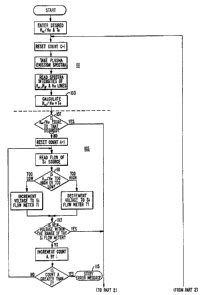
Referring to Figure 7, a flow chart is provided
of a controlling computer program that monitors the
intensities of the three emission lines and make adjust-
ments in the individual gaseous component flow rates as
1 32q 1 66
18
.,
required to maintain the electron temperature distri-
bution within acceptable limits. The process of Figure 7
can best be described as several functional modules. A
first module 101 requires information of both the desired
plasma parameters and those that actually exist. It is
preferable to enter a desired average electron tempera-
ture T and then calculate what exists in the plasma, ase
shown in Figure 7, since this permits the process operator
to deal with known quantities. However, since T is
proportional to the ratio of the hydrogen alpha and
hydrogen beta emission lines, that ratio itself could
more simply be substituted in the flow diagram of Figure 7
where T appears. It would then be that line intensity
ratio to which the process is adjusted.
Once the actual and desired quantities are in
the system, a next module 105 of the processing algorithm
looks at the intensity ratio between the hydrogen alpha
and the helium emission lines. A first step 107 compares
the actual and desired ratios. If they are within range,
then the processing component 105 is omitted completely
by jumping to a step 109 in the next module 117. However,
if the desired and actual ratios are not equal, a step 111
causes the flow meter 71 to be adjusted to change the flow
. ~
`,of silicon source vapor in a direction to move the
compared ratios closer together.
~>lA step 113 of the module 105 checks to make sure
that the calculated voltage is within the range ~f the
flow meter 71. If it is, the processing proceeds to a
:1
step 109. If not, the process loop of module 105 is
performed again. If the second calculation also results
in a voltage that is not within the range of the flow meter
71, then the processing is stopped and an error message
displayed for the operator, as indicated at 115.
:~ '
~ ,~
,~
,:
;~ .
,'
~r~
132ql6~
19
:`
Once the silicon source vapor flow rate is
adjusted, the next module 117 of the processing adjusts
the flow of oxygen to the plasma in response to comparing
the desired and actual T . If those quantities are equal
within an acceptable tolerance, then the processing loops
back to the beginning module 101 and performs the data
acquisition and comparison functions once again, and then
steps through the remainder of the program. This con-
stant monitoring of the plasma characteristics allows
real time control of the plasma for uniform film results
and repeatability of film properties from substrate to
substrate.
The program module 117 operates quite similarly
to that of 105. If the newly calculated voltage for the
oxygen supply flow meter is not within the range of that
flow meter, as determined by the step 119, the calculation
is made once more in case some error occurred. If the
voltage is not within the range the second time, the
processing is s~opped and an error message displayed.
Assuming, however, that the new oxygen flow meter valve
control voltage is within its range, the processing is
looped back to the beginning module 101 and repeated until
the processing modules 101, 105 and 117 have been
performed for a total of four times. After the fourth
time, and if the last calculation loop resulted in a
further adjustment to the oxygen flow meter, a next module
121 of processing is undertaken. After four ~imes
through the silicon source and oxygen flow rate adjust-
ments, it is concluded that some other adjustment must be
made. Of course, the precise number of processing cycles
that are allowed before going to the next calculation
module 121 can vary.
,
' -
:: , . . ..
:
:
1 32ql ~
The module 121 also looks at T, but in this
case adjusts the helium gas flow to the plasma chamber.
An increase of the inert gas supply provides more
electrons, and a decrease in the gas fewer electrons.
The same check on the calculated voltage for the helium
<, flow meter is made in the module 121 as in the modules 1~5
and 117, in step 123. Once a proper adjustment to the
helium flow is made, the processing again loops back to
the beginning module 101 to start the cycle over again.
Of course, there are many variations in the
; details of the process being described that can be changed
without sacrificing the advantages provided by the basic
emission line monitoring techniques that are so imple-
i mented. The same techniques are used with other gases
and even with a plasma that is part of a thin film
' sputtering system. In a sputtering system with a titan-
ium target, the intensity of a 399.9 nanometer emission
j line of titanium and a 301.3 nanometer emission line of
i titanium-nitride are measured, for example. A ratio of
the intensities of ~hese lines is used in the same manner
as the hydrogen alpha to helium ratio discussed above.
Two line intensities from argon can be used to calculate
the average electron temperature in this sputtering
example, corresponding to the hydrogen alpha line to
hydrogen beta line intensity ratio discussed above for
the PECVD example.
Plasma input variables of power of the supply
17 and pressure within the chamber 29 are not included in
the algorithm of Figure 7 as quantities that are adjusted
automatically. It has been found satisfactory to main-
'! tain those quantities fixed for at least a large
:! processing batch. This is preferably accomplished by
setting the control system 25 to the desired power and
/
.1 .
,''' :
",
"
,
.
:~ ~ 329 1 66
21
,
.
pressure. The control system 25 is provided with astandard capability of monitoring those quantities and
adjusting them, if necessary~ to maintain the constant
levels that have been set.
The spectra of the plasma 51, an example being
given in Fig. 3, is dependent upon the position within the
plasma which is observed. That is, the intensities of
the three emission peaks 81, 83 and 85, both absolutely
and relatively, are different depending upon where the
end of the optical fiber 23 is positioned with respect to
the quartz window 24 (Fig. 1) of the reaction chamber 11.
So long as this position remains fixed and the intensity
distribution across the plasma 51 does not change, the
techniques of controlling that process described above
optimizes it. But if it is desired to use that same
process control on a different piece of equipment, for
example, it is likely that the plasma will be viewed at a
location with a different emission spectrum. Thus, the
control system which has been optimized for one plasma
emission spectrum may have to be recalibrated to operate
with a spectrum having different relative intensities of
peaks of interest than in the plasma for which the control
system was optimized. Also, even in a single machine,
the spectrum can change across the plasma due to a change
in the substrate being coated, primarily in its thick-
ness, any change of gases, gas flow rates, a pumping rate
change, some relative change in the electrical power
being delivered to the system, and similar matters.
Therefore, to further optimize the control of
the plasma deposition process, a technique illustrated
with respect to Figs. 8-10 maintains an end of the optical
fiber medium 23 to gather light from the same relative
position in the plasma, regardless of any such changes.
, :
~ , ~ , .
:. .
, , : , .. .
... . ~ . ~
1 32~ 1 6~
22
As a preferred location, since it is relatively easy to
locate for any plasma, the optical fiber 23 is positioned
to view the plasma at the location where l:he ratio of the
intensities of emission into relevant narrow band-widths
is a maximum. In the example being descr.ibed, that ratio
is preferred to be the intensity of the hydrogen alpha
line divided by the intensity of the helium line of
emission.
Referring to Figs. 8 and 9, a mechanism will be
described for moving the optical fiber cable 23 with
respect to the transparent window 24 of the reaction
chamber in order to maintain this ratio at a maximum. The
optical fiber cable 23 is preferably terminated in a long,
small diameter cylindrical tube 301. The cable prefer-
ably contains dozens of individual optical fibersO The
purpose of the tube 301 is to limit the natural cone angle
of acceptance of light of the optical fiber end so that it
accepts substantially collimated light rays emitted from
an area of the plasma 51 that is substantially the same
size as the size of the opening of the tube 301 at an end
adjacent the quartz window 24. The inside of the tube 301
is made to be highly reflective.
The light-guiding tube 301 is attached to a
support block 303 that is carried with respect to the
reaction chamber 11 in a manner that allows it to be moved
in both X and Y directions. Appropriate control motors
are u~ed to provide such movement. An example is the use
of separate X and Y direction drive motors 305 and 307~
respectively, that drive the support block 303 through
respective mechanical connections 309 and 311 to move the
block 303 in those two directions. The motors 305 and 307
are controlled by position control circuits 313 which are
in turn connected to the system computer control 25 (Fig.
1) by an appropriate circuit 315.
, .
, : .'
~, ~; ' .
.~
13291~6
23
,
The block 303 can then easily be controlled to
move the optical fiber end tube 301 to a position to view
the plasma 51 where the ratio of the in~ensity of the
hydrogen alpha line to that of the helium line is a
maximum. This adjustment can be made as frequently as
each time a substrate is placed into the reaction chamber,
or, more practically, on a periodic basis or when the
nature of the substrate to be coated significantly
changes.
A number of specific ways of determining the
desired location may alternatively be implemented by the
mechanism o~ Figs. 8 and 9. One way is to scan the fiber
cable tube 301 in some raster pattern across the window
24, while the computer control system 25 calculates a
desired ratio from information obtained at several
locations of each raster scan line. The location of the
. ~
block 303 where the ratio is maximized is then determined
and the block returned to that position for monitoring the
plasma.
~ Another one of many ways of determining the
; maximum intensity ratio location is illustrated in Fig.
`i, 10. As a first step, the tube 301 is located at four
l spaced apart positions indicated at 317, 319, 321, and
1 323. The ratio of intensities is calculated for each of
those locations and the maximum determined. Assuming
that maximum in this example was obtained at the location
321, then the tube 301 is positioned at four ! other
locations spaced around the position 321, such as
positions 325, 327, 329 and 331. The maximum intensity
ratio for each of these four locations is noted J and
~ another four locations tested around that location, and
'`J~ SO forth.
.,
:
:'
.:,' , ~ .
.;.J,~ ' .
` 1 3~q 1 6~
24
:
~ Of course, as an alternative to the mechanism
-. described with respect to Figs. 8-10, the ~iber cable tube
301 can be adjusted in some manner by hand, while the
operator is observing the desired intensity ratio which
~' is being calculated by the system's computer.
.
Although the various aspects of the present
invention have been described with respect to its
preferred embodiments, it will be understood that the
invention is entitled to protection within the full scope
of the appended claims.
,
. !
"
, .
-!
,
,
' :
., ., , ~
' ~ , -