Note: Descriptions are shown in the official language in which they were submitted.
- 132~6
The present invention relates to an apparatus for
processing synthetic thermoplastic material, comprising a re-
ceiving container, containing a disintegrating and blending
member, which is disposed near the bottom of the ~ontainer
and which rotates about the axis of the container and with
which a screw extruder is in flow connection through an
opening in the wall of the container.
In such apparatus, the synthetic material, which is fed
into the receiving container from above, is engaged, dis-
integrated and thoroughly blended by the disintegrating and
blending members at the bottom area of the receiving
container. This results in a heating of the material. On
the one hand, the particles of material are moved by the
disintegrating and blending members about the vertical axis
of the receiving container along the wall of the container,
on the other hand, it is subjected to a rotating motion so
that, apart from a good blending action, a high thermal
efficiency is also ensured.
The material thus processed, is then to be contin-
uously delivered to the screw extruder and evenly discharged.
- 2 -
, ,~
13293~
For this purpose, proposals have already been made to
dispose the screw extruder radially to the axis of the
container. In an apparatus known from EU-PS 0045734, the
extruder cylinder with its charging opening extends far into
tAe receiving container; whereas in an arrangement according
to AT-PS 375867, the charging opening of the extruder is
flush with the inside wall of the charging opening.
Both embodiment variants are inflow technique most un-
favourable in regard to the synthetic material revolving inthe receiving container, and they do not permit a consistent,
continuous discharge.
The present invention eliminates the aforementioned
disadvantages and provides an apparatus which is of the kind
described first hereinbefore and which ensures a
troubleproof, absolutely even and continuous charging of the
screw extruder irrespective of temperature and rotational
speed.
This is accomplished according to the invention in that
the cylinder, surrounding the extruder screw of the screw
extruder, opens out with its front-end charging opening at
least approximately tangentially in the inside wall of the
receiving container.
- 3 -
f 13293~6
As a result of these steps, an even filling of the ex-
truder screw is ensured by the tangential flow components in the
rotating synthetic material, moving the latter into the area of
the container wall that is broken by the front-end charging
opening of the extruder cylinder and against the extruder screw,
whereby the latter is filled.
Depending on the apparatus, the material to be pro-
cessed, capacity and such like things, additional supporting
measures may be taken.
Thus, it is absolutely possible that the front-end
charging opening of the cylinder is flush with the inside wall
of the receiving container, or that the front-end charging
opening of the cylinder extends at least partially in the re-
ceiving container; the wall part of the cylinder, opposing the
rotational flow in the receiving container, forming, thereby,
a guiding wall for the deflection of the synthetic material into
the cylinder.
Furthermore, the development may also be such that
the free end of the extruder screw is set back in regard to the
front-end charging opening, respectively the guiding wall of the
cylinder.
In order to gain a further deflecting area, an
additional provision may be such that the cylinder widens funnel-
, . . ..
1~2938~
shaped at its area of connection opposing the flow in thereceiving container.
In one aspect the invention provides an apparatus for
processing synthetic thermoplastic material, comprising a
receiving container, containing a disintegrating and blending
member, which is disposed near the bottom of the container
and which rotates about the axis of the container and with
which a screw extruder in a cylinder is in flow connection
~o through an opening in the wall of the container; wherein: the
extruder extends perpendicular to a plane containing the axis
of the receiving container and tangentially on the receiving
container and opens out with its front-end charging opening
in the inside wall of the container in the area of its point
of contact with the tangent.
In a further aspect the invention provides an apparatus
for processing synthetic thermoplastic material comprising: a
receiving container having an axis running along a
longitudinal direction thereof, said container defined by a
wall and having an opening therein; a disintegrating-blending
member disposed near a bottom of said receiving container and
rotatable about said axis; and a screw extruder comprising a
screw within a cylinder, said cylinder having a front-end
charging opening being in flow connection with said opening
in said wall, said cylinder at its front-end charging opening
intersecting said wall at a tangent thereto, said
- 5 -
132~3~6
cylinder having a guiding wall forming part of said front-end
charging opening extending at least partially into said
receiving container opposing rotational flow in said
receiving container to achieve deflection of synthetic
thermoplastic material into said cylinder.
Embodiments of the present invention will now be more
particularly described by way of example and with reference
to the accompanying drawings, in which:
Figure 1 is a vertical sectional view taken on a plane
through the axis of the extruder of the apparatus for
processing synthetic thermoplastic material according to the
invention;
; Figure 2 is a vertical sectional view taken on a plane
through the axis of the extruder of this apparatus;
Figure 3 i8 a first embodiment variant of the
arrangement according to Figure l; and
Figure 4 i8 a further embodiment variant of the
arrangement according to Figure 1.
- 5a -
~'
:-
13~9386
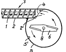
The apparatus represented in Fig. 1 and 2 comprisesessentially a receiving container 5, which contains a
disintegrating and blending member 6, which is disposed near
the bottom of the container and is mounted on the shaft 8 of
a motor 7 and is rotated about the axis of the container by
the motor. Above this disintegrating and blending member 6,
a screw extruder 3 with its front-end charging opening 4
extends in the receiving container 1.
Essential to the invention in this connection is that
the cylinder 2, surrounding the extruder screw 1 of the screw
extruder 3, opens out with its front-end charging opening 4,
at least approximately tangentially in the inside wall 5'.
In the arrangement as shown in Fig. 1 and 4, it is
intended that the front-end charging opening 4 of the
cylinder 2 extends at least partially in the receiving
container 5; the wall part 2' of the cylinder 2, opposing the
rotational flow in the receiving container 5, forming,
thereby, a guiding wall for the deflection of the synthetic
material into the cylinder.
The distinctions between the arrangements according
to Fig. 1 and 4 are that in the development according to
Fig. 1 the cylinder 2 of the screw extruder 3 passes
tangentially directly into the inside wall 5' of the
receiving container 5;
- 6 -
1329386
¦ whilst in the development according to Fig. 4, the cylinder 2
¦ is disposed parallel to the aforementioned according to Fig. 1.
¦ In this connection, the approximately tangential arrangement is
¦ functionally about equivalent to the direct tangential arrange-
ment, but may, however, prove to be better constructionally.
However the case may be, the arrangement may be such
that in both cases the free end of the extruder screw 1 is set
back in regard to the front-end charging opening 4, respective-
l ly the guiding wall 2' of the cylinder 2.
¦ In addition, it can be advantageous, in place of the
¦ development according to Fig. 1 and 4, to effect the arrangement
¦ according to Fig. 3, wherein the front-end charging opening 4
¦ of the cylinder 2 is flush with the inside wall 5' of the re-
¦ ceiving container 5.
I
¦ In order to create here a deflecting guiding wall 2',
the cylinder 2 may widen funnel-shaped at its area of connection
opposing the flow in the receiving container 5, as is illustrated
in Fig. 3.
In this manner, there results an apparatus for pro-
cessing synthetic thermoplastic material which, by comparison
with the known prior art, accomplishes an optimum filling of
l the discharging screw extruder in every operating condition.
.. ~, ,
132938~
Of course, in this connection, various modifications
within the bounds of the basic idea of the present invention are
possible. The main essential condition being the at least approxi-
mately tangential transition of the front-end charging opening
of the extruder cylinder in the inside wall of the receiving
container.
How far the cylinder extends, thereby, into the re-
ceiving container, whether it is then opened out funnel-shaped
and where the screw extruder ends as regards the front-end
charging opening of the cylinder, is subject to the requirements
set on the material to be processed, the volume, the processing
speed and such things.
I .
¦ While there are shown and described preferred embodi-
¦ ments of the invention, it is to be distinctly understood that
I the invention is not limited thereto but may be embodied and
¦ practised within the scope of the following claims. ACCORDINGLY,