Note: Descriptions are shown in the official language in which they were submitted.
-1 ~3294~
The present invention relates to a quick-
connect, totally implantable cardiac prosthesis incor-
porating floating membranes and removable sensitive
5 elements.
Such a prosthesis is intended for an implanta-
tion which is either temporary whilst awaiting a
heart transplant, or definitive in patients who cannot
benefit from a transplant for medical or other reasons.
Such prostheses have already formed the subject
matter of several prio~ inventlons.
This prosthesis is essentially constituted
15 by a biventricular one-piece assembly which comprises
a tight shell implantable in the pericardiac cavity,
made of a material which is compatible and non-toxic
with respect to the surrounding tissues and presenting
a specific geometry, which reproduces the configura-
20 tion of the natural hear~ in two right and left ventri-
cular chambers.
This prosthesis contains: 1) a device for
pulsion of the blood essentially constituted by two
membranes, of which one defining the right ventricle
25 works in elongation and of which the second defining
the left ventricle works in deformation; 2~ valves
mounted in the inlet and outlet orifices; 3) means
for activating the above-mentioned pulsion membranes
which furnish them with supply pressures substantially
30 equivalent to the physiological values; 4) means
for regulating the cardiac output as a function,
on the one hand, of the filling pressure and, on
the other hand, of the aortic pressure.
However, with such a prosthesis, a) the activa-
35 tion and regulation means controlling the pulsion
r , ~
1329~0
--2--
membranes is not mounted directly on -the prosthesis,
which increases the volume of the whole and compli-
cates implantation thereof; b) -the activation means
is unique for the two me~branes, rendering the prob-
5 lems of regulation more delicate and random; c) theprosthesis is not rendered biological; and d) it
does not allow replacement of certain of its functio-
nal elements, which operation may prove necessary
in the event of a failure or wear and which it is
10desirable to be able to effect without changing the
whole prosthesis.
U.S. Patent No. 4 397 049 (ROBINSON et al)
describes a cardiac prosthesis comprising two ventri-
cular chambers, each being provided with two orifices,
15one serving for the inlet of the blood, the other
for ejection, and with an activation device constitu-
ted by an electro-pneumatic member. However, each
chamber presents only one flexible membrane.
Patent FR 2 370 1~4 (NI~KIOS) describes a
20pulsatile pump for blood circulation comprising a
driving pouch provided with an inlet orifice and
with a delivery orifice provided with valves, said
pouch being in contact with a pressure transmission
chamber defined by a diaphragm and compressed by
25a piston to generate a movement corresponding to
the physiological pulsation. However, this pump is
not implantable.
U.S Patent No. 3 478 695 (GORANSON et al)
descrihes a heart pump with a chamber comprising
30at least two deformable enclosures, the first being
connected to a source of pressure and the other being
connected to the heart; pressurization of the first
having for its effect to compress the second directly
upon contact and thus to provoke delivery of a deter-
35mined volume of blood towards the heart. The bladder
- . ,
: , : . - ' :
1329~0
inflates under the effect of the pressurization of
the flrst enclosure and makes it possible to avoid,
after delivery, the second enclosure resuming its
initial shape too rapidly by suddenly sucking a fresh
volume of blood.
However, this pump cannot be mounted directly
either on the heart or on any prosthesis.
The present invention overcomes these drawbacks
10 for the first time and in satisfactory manner by
proposing an implantable cardiac prosthesis constitu-
ted by a quick-connect, one-piece module comprising
two ventricular chambers, rendered biological, com-
pletely independent and activated separately, each
15 ventricular chamber being provided with two orifices
provided with valves - one of the orifices serving
for ejection, the other for inlet of the blood -
and with a separate activation and regulation device
constituted by an electro-mechanical membex and by
20 a pair of membranes, characterized in that the first
membrane is a mechanical membrane actuated either
by a transmission fluid pressurized by means of said
electro-mechanical member, or by a piston animated
by a motor in accordance with the so-called pusher
25 plate mode, and the second membrane, in contact with
the blood, is a floating biological membrane, moving
under the action of the first membrane during systole
and under the action of the pressure of the blood
during the diastole.
The displacement of the membranes necessitates,
on the one hand~ a fluid reservoir constituted by
a deformable sac enveloping the prosthesis, on the
other hand, a compliance chamber connected to the
space separating the two membranes. This latter cham-
35 berj by its sub-cutaneous position which is therefore
4_ 1329~
easily accessible by transcutaneous puncture, makes
it possible to obtain useful information on the pres-
sures, volumes and possible modifications of the
fluid between membranes. It also possibly allows
permanent or temporary communication with the open
air.
~ nother feature of the prosthesis of the inven-
tion lies in the arrangement of the inlet ducts
of the two ventricular chambers which are grouped
10 and connected on the same bezel element, said bezel
being removably and rapidly connected to a receptacle
of identical shape sutured on the patient's natural
atria.
The bezel sutured on the atria and which serves
15 as receptacle for the prosthesis is in one piece
and provided with suture devices ensuring tightness.
It may be temporarily obturated by an occlusive plate
which makes it possible to check the tightness of
the receptacle before implanting the prosthesis.
The prosthesis of the invention further com-
prises, on the wall of the ventricular chambers as
well as on each of the membranes, sensors adapted
to determine at any instant the positicn of the floa-
ting membrane in order to adjust the flowrate and
working frequency of the electro-mechanical member
with a view to regulating the stroke of the membranes
and the frequency OL the beats.
The membranes, electro-mechanical members
and valves, elements most sensitive to wear, are
30 removably mounted on the module in order to allow
rapid standard replacement thereof.
The originality of the cardiac prosthesis
of the invention also resides in the complete separa-
tion fthe physiological problems from the mechanical
35 problems. The part in contact with the blood is
: - : . . . : . ~ -
.; , - . ~ . . , .
,
~5- ~3294~0
constituted by haemocompatible materials and compo-
nents. The electro-mechanical members are not in
contact with the blood, which limits the extent of
the problems to be solved. ~nother original element
is the single--piece design with a separate motoriza-
tion of the two ventricles so as to facilitate their
respective regulation.
The cardiac module proper therefore comprises
two independent ventricular chambers having the Eunc-
tions of right ventricle and of left ventricle, fourorifices (one inlet duct and one ejeetion duct
for each chamber), four valves (one for each orifi,ce)
and two membranes in each chamber.
The electro-mechanical members ensurer for
each ehamber of the module, actuation of the membranes
at a given fxequency with a given stroke, thus allo-
wing regulation of the blood outputs by varying the
frequeney and/or the volumes displaeed.
The electro-meehanical pulsion members and
eleetronic regulation members are totally isolated
from the blood medium. They are miniaturized, mounted
on the module in an appendieular arrangement and
in the free spaces between the two ventrieular cham-
bers. The appendicular arrangement which constitutes25 an original element of thi,s prosthesis allows their
transpericardiac arrangement in the pleural cavities,
this eonsiderably reducing the intraperieardiac dimen-
sions and facilitating heat exchanges between the
driving members and the lungs.
It is therefore the membranes whieh eonstitute
the "physical and biological interface" between the,
blood medium and the electro-mechanieal members.
The blood output must be able to be permanently
modified as a function of the organism's requirement,
either by varying the volume of admission and/or
, :. : . . . .
-6- 1 32 9~ ~ 0
by varying the volume of ejection and/or by varying
the frequency.
In ~he prosthesis according to the invention,
the system for regulating output is as follows: the
"mechanical" membrane moves under the effect of the
electro-mechanical or electro-hydraulic actuator
between a position of advance (systole) and of with-
drawal (diastole). A first element of regulation
is constituted by the possibility for this membrane
lOto cover all or only part of its stroke both during
systole and during diastole. The floating membrane
for its part adds a second complementary element
of regulation more sensitive than the preceding one.
Its diastolic displacement is a function of the pres-
15sure and of the filling volume of blood. A thirdelement of regulation is the frequency of displacement
of the membranes. These three elements of regulation
are put into play either passively or actively as
a function of information obtained by different sen-
20 sors, of which the one which makes it possible toknow at any moment the position of the floating mem-
brane is only one element.
The sensors are sensors of positioning of
the two membranes, sensors of pressure and sensors
25 of partial oxygen pressure, located in the different
afferent or efferent cavities or vessels.
The heart is a pulsed output generator and
the pressure curves are entirely determined by the
force of pulsion on the membranes, the opening/closure
30 of the valves, the haemodynamic conditions of the
upstream and downstream networks (compliance pres-
sures). The shape of the pressure curve of the pros-
thesis according to the invention therefore optimally
reproduces the curve of evolution of the volume deli-
35 vered as a function of time.
The floating membrane, called biological mem-
-7- 132~4~
brane, which constitutes the interface with the blood
is therefore actuated by a second membrane, called
mechanical membrane. This latter is itself actuated
by a piston of the so-called pusher plate type or
preferably by a fluid which allows a better distribu-
tion of the mechanical stresses. The pressures gene-
rated in the ventricu]ar chambers are generally of
the order of 100 to 140 ~unHg for the left ventricle
and 35 to 40 mmHg for the right ventricle. The so-
called -transmission fluid is moved by the electro-
mechanical member and more particularly by a hydraulic
positive displacement micro-pump itself combined
with a brushless D.C. micromotor or autosynchronous
motor with sufficient power.
Output may be varied by var~ing the speed
of the motor, the frequency of reversal of direction
of the motor, or by changing the volumetric displace-
ment of the pump.
~his micromotor is immersed in the transmission
liquid and presents electronic controls. The liquid
is stored in a reservoir constituted by a deformable,
non-elastic, tight ~nvelope surrounding the cardiac
module and the electro-mechanical and electronic
members.
The hydraulic solution eliminates the problems
of mechanical wear of the membranes. The mechanical
membrane is not floating and its position depends
on the volume delivered by the pump.
The cardiac module also presents sensors of
blood pressure, and for assessing filling of each
of the ventricles or of the reservoir containing
the transmission liquid. The cardiac module a]so
presents sensors for measuring the partial oxygen
pressure of the left and right cavities using colori-
metric processes.
.. . .............. ~ .. . . . . .
. . .,; . .. ~ ,.. :,
-8- 1 3 2~ ~5 0
The electronic control of the autosynchronous
motor exploits the position information given by
the sensors of the rotor, effects synchronization
of the rotary field with the permanent magnet and
amplifies the signal delivered to the coils of the
stator.
The motor is regulated with a digital electro-
nic card presenting logic integrated circuits which
make it possible to reproduce the cardiac cycle by
10 modulating the durations of reversal of direction
and by monitoring at each instant the speeds of rota-
tion, the acceleration and the braking.
This card is used with an electronic card
for exploiting the signals coming from the sensors
15 of cardiac state and with the electronic microproces-
sor which monitors and regulates the cardiac output.
The electxic motors, the pumps, the electronic
elements and the sensors are immersed in the trans-
mission liquid in order to facilitate the heat loads
and to reduce noise.
The invention will be more readily understood
on reading the following description with reference
to the accompanying drawings, in which:
Fig. 1 shows an overall view of the cardiac
prosthesis according to the invention.
Fig. 2 is a view thereof in transverse section
representing the systolic and diastolic positions
of the floating membrane.
Fig. 3 is a plane view from above of the recep-
tacle on which is removably connected the inlet bezel
of the module.
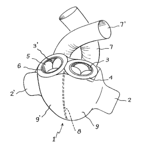
Fig. 1 is an overall view of the cardiac pros-
thesis according to the invention.
-9- 1329~50
This Figure shows the appendicular arrangement
of the electro-mechanical members 2, 2' on the module
The two admission ducts 3, 3' grouped side
r. by side on one single be~el 4 are provided with admis-
sion valves 5 and with a seal element 6. The bezel
4 is adapted to be quickly and easily connected to
a receptacle 30 (not shown in this Figure) sutured
on the patient's natural atria. The two ejection
ducts 7, 7' are independent and are provided with
ejection valves S' (not shown in this Figure). These
ducts are sutured directly on the arteries. Wall
8 completely isolates ventricle 9.
Fig. 2 is a transverse half-section of the
prosthesis of the invention. In this Figure, only
the left heart constituted by the left ventricle
9 has been shownt wall 8 completely isolating it
from the right ventricle 9'.
Ventricle 9 is divided into two parts: a bio~
logical chamber 9a and a mechanical chamber 9b, the
interface between these two chambers being constituted
by a mobile biocompatible membrane 10. It is therefore
the position of this membrane 10 which determines
the volume of the biological chamber 9a and consequent-
ly the quantity of blood admitted or ejected. Themembrane 10 is floating, i.e. mobile unilaterally
between the systolic position corresponding to the
end of the period of ejection, moment when the biologi
~ al chamber 9a has a minimum volume, and the diastolic
position corresponding to the end of the period of
admission, moment when the biological chamber 9a
has a maximum volume (of the order of 60 to 80 cc),
depending on the size oE the prosthesis.
The membrane 10 is actuated by a second, so-
called mechanical membrane 11. During the phase of
~ . - ::; . . - :
-: . . ~ . ...... : , - : . :
- . ........ : : ,. . . - . . : . .: . . , : . ,
: . : . : ~
1329~0
-1 0--
ejection, the membrane 11 pushes membrane 10 from
the diastolic position to the systolic position,
then, during the phase of admission, the membrane
10 returns to the diastolic position under the simple
effect of the blood pressure.
The diastolic position of the membrane 10
corresponds to an equilibrium on either side of said
membrane between the filling blood pressure (which
is of the order of 10 mm~g for the left heart and
8 mmHg for the right heart) and the compliance chamber.
Between the biological membrane 10 and the
mechanical membrane 11 there exists an intermediate
free volume 12 occupied by a fluid maintained during
diastole at a pressure slightly less than or equal
I5 to the pressure of filling of the right heart or
of the left heart. This free volume 12 is in communi-
cation with a compliance chamber 13 easily accessible
from outside the body in order to be able, if necessa-
ry, to readjust the pressure of intermediate free
volume.
The mechanical membrane 11 is itself ac-tuated
by means of an electro-mechanical member 12 via a
transmission fluid 14 (and preferably a liquid) stored
in the reservoir constituted by a tight deformable
envelope 15 surrounding the module 1, the electro-
mechanical members 2, 2" and the regulation elements.
This arrangement makes it possible ~o reduce the
noise of the mechanical elements and promotes heat
exchanges.
The electro-mechanical member 2 is therefore
immersed and is composed of an electric micromotor
21 combined in the case of the Figure with a hydraulic
micropump 22. The micromotor 21 may for example be
an autosynchronous motor. During the phase of ejec-
tion, the micropump 22 sucks the liquid 14 directly
: .
., . ~ ... . . - :
. : . - :: : ~ . : . ~ .:
.. : ~ .
-ll- 132~450
in the reservoir 15 and delivers it in a very short
time against the mechanical membrane 11 to push it
in contact with the biological membrane 10. During
the phase of admission, the micropump 22 sucks the
liquid 14 previously in contact with the membrane
11 to deliver it in reservoir 15, which has for its
effect to return the membrane 11 to its position
oE rest. The frequency of the heart beats therefore
corresponds to the frequency of reversal of the direc-
tion of rotation of the micropump 22. The strokeof the membrane 10 depends on the stroke of the mem-
brane ]1 and therefore on the volume of liquid 14
delivered by the micropump 22 but also on the ventri-
cular filling pressure. The micromotor 21 and the
micropump 22 are controlled by an electronic monito-
ring and regulation device comprising a set of analog
sensors 23 mounted in particular on the wall 8 and
on the membranes 10, 11 in order continuously to
know the position of the membranes, the frequency
of the beats, the blood pressure inside the ventricu-
lar chamber and the compliance chamber, the pressure
of the transmission liquid, the partial oxygen pres-
sure, etc... The information furnished by the sensors
23 is used by the electronic monitoring device to
automatically modify or adjust the operational para-
meters of the module 1 to predetermined values.
The ventricle 9, with reference to Figs. 2
and 3, presents two orifices, one serving as admission
duct 3 and the other as ejection duct 7. These ori-
fices are respectively provided with an admission
valve 5 and an ejection valve 5' and cause the ven-
tricle 9 to communicate with the rest of the circula-
tory system. The ejection duct 7 is adapted to be
sutured directly on an arteryO
The admission ducts 3, 3' of ventricles 9,
-12- 1329~0
9' are grouped and connected on the same be~el 4.
The bezel 4 itself is removably and quickly
connected on the receptacle 30 sutured on the pa-
tient's natural atria.
All the fragile elements or those likely to
wear out quickly, such as the valves, micromotors,
micropumps and membranes, are removably mounted on
the module in order to be replaced easily without
changing all the module 1.
The receptacle 30 is constituted by a bezel
34 symmetrical to the bezel 4 and on which the module
1 is removably and quickly connected. Its originality
comes from the fact that it is in one piece connecting
the two admission orifices 32, 33. It comprises a
15suture element constituted for example by a peripheral
suture ring 36 made of fabric (for example Dacron),
completed by an inter-orifice fastening tape of the
same fabric. The inter-orifice fastening tape compri-
ses regularly spaced apart perforations for the pas-
20sage of the suture threads and a notch adapted tohouse the knots of the suture threads in order to
ensure perfect join between the receptacle and the
prosthesis. This receptacle may be occluded by a
plate 16 (cf. Fig. 2) to check the tightness of the
25sutures. It presents seals with the prosthesis and
the quick-connect elements 35.