Note: Descriptions are shown in the official language in which they were submitted.
133~5
BACKC~ROUND OF THE INVENTION
2 The present invention relates to a compresslon molded door assembly.3 Compression molded door assemblies comprise a separate class of doors. A prior
4 art compression molded door nssembly is disclosed in my U. S. Patent No.
4,550,540, which was granted November 5, 1985.
6 Compression molded door assemblies include outer compression molded7 door skins which have a textured pattern on the outer side of each skin which
8 simulates, tor example, grain and texture of n wood door.
9 The compression molded door assemblies nre often superior to a wood door
in that they have dimensional stability which resists excessiYe deflection ~nd
11 warping caused by temperature and humidity differentials.
12
.. . . . .
13 SUMMAIIY 0~ THE INVENTION
14 The present invention is directed to a compression molded door assembly
15 which does not include n rectangular frame found in most prior art compression
1~ molded doors.
17 The outer sides of the compression molded skins define n textured pattern
19 simulating the grain nnd texture of a wood door. An integrnl edge member
19 extends outwardly from major portions of the top, bottom and side edges of the
20 door skins. The integral edge member mates with a similar integral edge
21 member extending outwardly from the edges of the opposed compression molded
22 skin.
23 The primary object of the present invention is to provide a compression
24 molded door nssembly that is both attractive and also has strength and
25 dimensional stability.
2~ Another object of the present invention is to provide a door assemMy which
27 Es simple and economical to manufacture.
28 A further objcct of the present invention is to provide n door assembly
29
., .
133001~
whieh can utilize a number of diterent types Or materials or structural
2 configurations îor the core.
3 Other objects and advantages will become apparent from the description
4 and drawings.
6 DETAILED DESCRIPTION OF TT-IE DRAWlNGS
7 Fig. 1 is an exploded view oi one embodiment Or a compression molded
8 door assembly according to the present invention and showing one type of core;
9 Fig. 2 is an exploded view of another embodiment of the present invention
10 and showing another type of core;
11 ~ig. 3 is an elevntionnl view of a comprcssion molded door assembly,
12 according to the 2resent invention;
13 ~ig. 4 is a cross-scctionnl view tnken nlong the line ~-~ Or ~ig. 3;
14 Fig. 5 is a fragmentary cross-sectional view in the area of the right end of
15 line 4-4 of Fig. 3 showing another type of edge construction;
1~ Fi~. 6 is a view similar to Fig. 5 showing yet ~nother type Or edge
17 construction;
1~ ~ig. 7 is an explodcd view of another embodiment ot the present invention;
19 and,
~ l~ig. 8 is an exploded view of yet another embodiment.
21
22 DETAILED DESCRIPTION OF THE PREFER~ED EMBODIMENTS
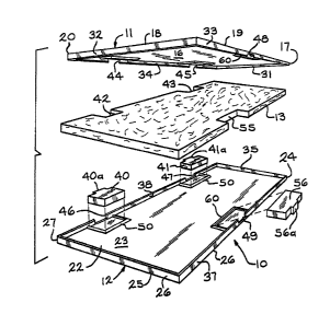
2~ 1~ eompression molded door nssembly, according to the present invention, is
24 generally indicated by the reîerence number l 0 in ~igs. 1 and 3. The
25 compression molded door assembly I0 includes n pair ot opposed compresssion
2~ molded door panels or slcins ll and 12. The interior of door assembly l0 is often
27 filled with fl foamed core 13 but may be filled with one of m~ny different types
28 of materials including ~ibrous glass insulation blanket, n rigid formed expnnded
29
5~ 3
1330~15
fibrous glass insulcltion member as shovJn at 13n in ~ig. 2, or loose fibrous giass
2insulation particles.
Each of the skins 11, 12 is a compression molded sheet moldin~ compound
4(SMC) panel which includes 15% to 40% fibrous glass reintorcement, by wei~ht,
5and 10% to 40% inert materi~l filler, by weight, in the molding resin.
6'Jnsaturated polyester polymers blendcd with vinyl monomers such IIS styrene nre
7molding resins that may be cured under heat and pressure to form the thermoset
8compression moldcd skins. The molding resins include unsaturnted polyester
9resin compositions nnd modifications ns disclosed in, ror examples, U. S. Patent
10Nos. 3,772,241, and 3,883,612.
11The inert riller mQy be, for exnmples, calcium carbonnte or nluminum
12trihydrate. In some embodiments, the materiAl may nlso include ultraviolet
13 stabilizcrs and tire retardant ndditives in the composltion.
14Each of tlle sl~ins 11, 12 hns a thickness of betwecn 0.050 inch nnd 0.120
15inch. The prescnt embodiment shown }n I;ig. 1 has a skin thickness Or 0.070 inch.
eîerring to Figs. 1 through 4, the compression molded skin 11 hns nn outer
17side 15, nn inner side 16, top and bottom edges 17, 18 and opposed side edges 19,
1~ 20.
19Similarly, the compresssion molded skin 12 has an outer side 22, an inner
20side 23, a top edge 2~, n bottom edge 25 and side ed~es 26, 27.
21The outer sides 15 and 22 of the skins 11 and 12 include n molded wood
22 grain texture. Thè texture is important and simutates from a texture viewpoint
23 and a grnining viewpoint a v,lood door. The texture on the outcr sides 15 and 22
24is between 0.003 inch nnd 0.009 inch in depth. The outer sides 15 nnd 22 of the
25 s~ins 11 and 12 are essentially devoid of glass ibers for ~ predetermined depth
2~Or at least 0.005 inch. The predetermined depth, where the outer sides 15 and 22
27are essentially devoid of glass fibers, is norrnally betwecn 0.005 inch and 0.009
28 inch.
. ~
1330~5
While the inner sides 1~ and 23 of the skins 11 ~nd 12 mny Qlso hnve a
2 defined pattern or rnndom texture molded into the skin, tllis is not essentinl to
3 the invention.
4 If desired, one oi the slcins, for e~ample, that depicted by the numernl 12,
may be rormed of materials other than those specified above for forming
6 compression molded sklns. ~or exnmple, ii it is not important to have the
7 molded v,~ood grain texture on the outer surfnce 22 Or skin 12, it m,ly be formed
8 of nny Or a wide v~riety Or plnstic mnterinls cnpflblc Or being e~ctrudcd or cnst
9 such as polyethylene or polycarbonate or it may be formed of ~etal such
as steel or aluminum.
11 In tl~e embodiment shown, a rectangulnr woodcn or other rectnngular ~rame
12 is not provided. In the present embodiment ench of the edges 17, 18, 19, nnd 20
13 ot the compression mol~ed skin 11 is provided with nn intcgrnl edge member 31,
14 32, 33 and 34, which extend outwardly from thc edges 17, 18, 19 nnd 20,
respectively, Or the door skin 11. Similarly, integral edge members 35, 3~, 37
1~ and 38 e~tend outwnrdly from thc edges 24, 25, 26 and 27, respectively, of the
17 door slcin 12.
18 The integrnl edge members 34 nnd 38 have a first set of notches 44 nnd 4G,
19 respectively, which arc aligned Yvith cach other and n second set ot notches 45
20 and 47, respectively, which are also nligned vlith ench other. The respective set
21 o~ notches 4~ nnd 46, ~5 and 47 are positioned to be allgned with hinges of a
22 mounting structure (not shown). The opposite integral edgc members 33 nnd 37
:23 nre also providcd Witll notches ~8 nnd 49 which nre aligncd with onc nnother nnd
24 with a door lntch retention (not shown).
In order to provide menns ~or hanging the compression molded door
2~ ~ssembly in an opening, a pair oî mounting blocks 40 and 41 is provided. The
27 mounting olocks 40, ~1, which may be formed of wood or other material suitable
28 tor retention to hinges by screws or other suitable anchoring means, nre
29
.~ . ,.
13~3~13
positioned between the compression molded skins 11 and 12 ad~acent the edge of
2 the door assembly formed by the ed~es 20 nnd 27, respectively, of skins 11 and
3 12. The core 13 or 13n is provided with notched areas 42 and 43 along one edge,
4 each oî which is sized to snugly reccive one Or the mountino bloclcs 40 o~ 41.
The notched area 42 is positioncd in alignment with the locntion of the fi~st set
6 of notches 44 nnd 4G Or the integral edge members 34 nnd 38 ~nd the notched
7 area 43 is positioned in alignment with the second set of notclles 45 and 47.
8 Mounting block 40 is provided ~Nith a projection 40n which extends through
9 the first set of notchcs 44 and 4G and mounting block 41 is provided with a
projection 41a whicil extends througll the second set of notches 45 and 47.
~1 Additionally, the inner sidc 16 of skin 11 and inner side 23 oî the sl<in 12
12 may each be provided with t~no molded dams 50, each having a size and
13 confi~uration and so located as to snugly reccive onc of the mounting block~ 40
14 nnd 41. Thus, when the inner nnd outer door skins 11 nnd 12 are joined and
sealed around thc core 13, the mo~nting blocks 40 nnd 41 will be retnined
1~ between thc inner sur~ces lG and 23 Or the rcspective door skins 11 and 12 nnd
17 held in position by one of the dams 50 and the integra1 edoe members 34 and 3R
18 with the projection 40a of the mount block 40 extending through the first set of
19 notches 44 and 4G nnd the projection 41a of the mounting btock 41 extending
through thc second set of notches 45 and 47.
21 Similarly, l:he opposite edge of the core 13 is provided with a notched area
22 55 which is sized to rcceive a door latch retuining mechanism 56. The integral
23 edge members 33 and 37 are provided with notches 48 and 4~, respectively which
24 are aligned witll cach other and with the notched area Or the core 13. The door
25 latch retaining mechanism hns a projection 56a which extends through the
2~ aligned notches 48 nnd 49. Additionally, the inner surface 16 of door skin 11 and
27 inner surface 23 of door skin 12 are each provided with a molded dam ~0 which is
28 sized to snugly receive and retain thc door latch retaining mechanism 5G.
29 G
-`" 133~
As shown in ~ig. 4 the door skins 11 and 12 are joined at a butt joint 61
2formed by the nbutting ends of the integral edge numbers 33 and 37 (as shown in
3Fig. 4) and the abutting ends of the other integral and opposing edge members 31
4and 35 at the top, 32 and 36 at the bottom, and 3~ and 38 along the hinge side of
5the door. If desired, instead of a butt joint, a lap joint 62 in the form sh~wn in
6Fig. 5 or Fig. 6 may be provided. Adhesives such as thermosetting contact
7adhesives may be utilized for adhering the respective members forming the
8 joints.
gRererring now to Fig. 7 there is shown a modified embodiment in which a
10pair Or boards 65 and 66 may be provided along each edge of the door nssembly
1110'. The board 65 on the hinged side of the door is provided with A pnir of
projections 65~ positioned in alignment with the respective sets of notches 44',
1346' and 45', 47'. The skins 11' and 12' of the embodiment shown in Fig. 7 have
14lon~itudinal walls 67 formed on their inner surfaces 16' and 23' for retaining the
15 board 65 in position.
Similarly, the board 6G on the door lntch side Or the door is provided with
17 projection 6Ga so that the bo~rd 66 may receivc n door latching mechanism
which extends out Or the edge Or the door for latching in a door frame. The top
19and bottom skins 11' and 12' respectively, are provided with notches 48' and 49'.
20 respectively, through which the projection 66a Or the board 66 may e~ctend.
21In this embodiment there is provided a core 68 having a simple rectangular
22configuration. The core 68 iits snugly between the longitudinal w911s 57
23retnining boards 65 nnd 66 and sbuts the upper end formed by thc abutting
24integral edge members 31' and 35' and the lower integral edge members 32' and
2536' and is, Or course, positioned snugly between the inner surfaces 16' and 23' of
2~s the respective door skins 11' and 12'.
27Referring now to Fig. 8 there is shown a modified embodiment in which
28there is provided n lattice-like core frame 70 which may be tormed Or molded
29 thermopl~stic material or other suitable material for forming a lattice-like
30 structure. In this embodiment n loose pack of fiberous glass filler 71 or similar
0 ~ ~ ~
suitable insulRting material is positioned within the openings of the l~ttice-like
2 structure to provide the insulative feature desired for the door assembly. The
edges of the respective upper door slcin 11" and 12~ ' are provided with integral
4 edge members flnd may be sealed in a manner similar to that as shown in Figs. 4
50r6.
6 If it is desired to h~ve one of the skins, îor example, that depicted by the
7 numeral 12, formed of metal or plastic sheet material, the other skin 11 which is
8 compression molded will be provided with integr~l edge members 31, 32, 33 nnd
9 34 which are sufficiently long to span the full thickness of the core 13 nnd join
the metal or plastic material forming the skin 12.
11 It c~n be rcadily seen that ~ door of the present invention cnn be easily nnd
12 economic~lly assembled with the internal components snugly retained between
13 the respective skins to rorm n functional nnd economicnl door nssembly.
14 While the present invention has been disclosed with respect to the
embodiments, it is understood that various changes nnd modifications may be
1~ made to the compression molded door nssembly without departing from the scopc
17 of the following claims.
1~
19
21
22
23
24
27
28
29 8