Note: Descriptions are shown in the official language in which they were submitted.
"`` 133~60
BLOW MOLDED CCNTAINER WIl~ SELF-SUPPORTING BASE
Backgrcund and Summary of the Invention
me present invention relates to hollow plastic containers and,
more particularly, to blow molded plastic containers with self-supporting
bases. The base has sufficient strength to withstand internal pressures
like those encountered in the packaging of carbonated beverages and the
like, and in addition has distinct supporting feet which enable the
container to stand without rocking.
With the movement to plastic bottles for packaging car~onated
beverages, the art has moved to plastic containers with self-supporting
bases~ Such a container must be able to withstand the internal pressure
necessary to maintain the desired carbonation. Such a pressure is on the
order of 75 p.s.i.
Several types of containers exist in the art that include
integral bases with molded bottom configurations. Hcwever, there still
exists a need for a container of this type which requires a reasonable
amount of material in the base, withstands internal pressures and will
stand upright with out rocking.
The present invention provides a container having a tubular body
and an integral base, the junction of the two having a smooth, continuous
exterior surface. The present invention eliminates any sharp bends
deviations, or the like at the junction of the body and base. me present
invention provides the container with good distribution of plastic
throughout the container surface. Also, the present invention eliminates
stress cracks and enables the use of a minimum amount of plastic material
to mold the container. Also, when the container is full of a carbonated
beverage or the like, the container will withstand the pressure necessary
1~3~60
to maintain carbonation and will exhibit a very sturdy and
rigid outer body. Once the beverage has been removed from
the container, the container is very flexible and enables
the container to be discarded and the plastic re-cycled.
Accordingly, the present invention provides an
improved blow molded plastic container having the above
advantages. The container includes a tubular body
terminating at its lower end in an integral base. The base
lncludes a truncated frusto-conical shape inner wall
projecting into the interior of the tubular body. The
frusto-conical shaped inner wall terminates at its upper end
in a substantially planar top surface. Outwardly of the
inner wall the container has a downwardly concave annular
chamber bounded on the radially inner side by the inner wall
of the base and on the radially outer side by the outer wall
of the base. A plurality of substantially inverted V-shaped
ribs are formed radially about the base between the
frusto-conical inner wall and the outer wall of the base.
The ribs extend upwardly from the base a small distance so
as to intersect the inner and outer walls at a position
substantially more than half the distance from the top
surface to the base and form in the base a plurality of feet
arranged in a circular formation and symmetrical with
respect to the container axis. The feet are formed between
sg/ lcd
F =`; -
. ~,;, .
133~0
the ribs and have a wide dimension in a direction
circumferentially of the base to provide firm support for
the container when standi.ng.
From the subsequent description and claims taken
in conjunction with the accompanying drawings, other objects
and advantages of the present invention will become apparent
to those skilled in the art.
Brief Description of the Drawings
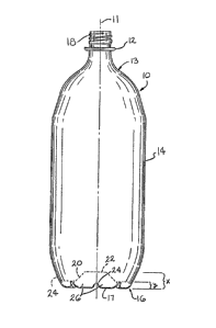
Figure 1 is a side elevation view of a container
in accordance with the present invention:
Figure 2 is a bottom plan view of the container in
Figure l;
--2a--
sg/lcd
133~60
Figure 3 is an enlarged sectional view of a portion of the
container as seen from substantially the line 3-3 in Figure 2;
Figure 4 is an enlarged sectional view of a portion of -the
container as seen from substantially the line 4-4 in Figure 2;
Figure 5 is a fragn~ntary side elevational view of a n~dified
form of container of the present invention;
Figure 6 is a bottom plan view of the container shown in Figure
5;
Figure 7 is an enlarged sectional view of a portion of the
container as seen from substantially the line 7-7 Figure 5.
Detailed Description of the Preferred Embodiment
With reference to the drawing, the blow molded plastic container
of this invention is illustrated and designated generally at 10 in Fig. 1.
l~e container 10 includes an integral tapered top portion 13 which includes
a flange 12 and a threaded neck 18. The container also has a hollow
tubular body 14 and an integral base 16.
The tubular thin wall body 14 is m2u~ufactured, as is the entire
container, fro~ a blow molded plastic material such as polyethylene
terephthalate (PET).
The base 16 includes a frusto-conical upwardly narrowing inner
wall 20 and a substantially circular and planar wall 22 projecting into the
interior of the hollow tubular body 14.
Outwardly of the inner wall 20, the container 10 has a downwardly
concave annular chamber 23 bounded on the radially inner side by the wall
20 and on the radially outer side by the outer wall 25 (Fig. 3) of the base
16. A plurality of internal ribs 24 are formed in the base 16 between the
walls 20 and 25, the ribs 24 being symmetrical relative to the longitudinal
axis 11
--3~
133~60
of the container 10. A pluraiity of feet 26 are formed between adjacent
ribs 24 to enable the container 10 to stand upright.
The ribs 24 are formed by elongated narrow indentations formed on
the surface of the base 16 as seen in Figures 2-4 so that the ribs 24
extend radially of the base 16. The positioning of the ribs 24 such that
the ribs 24 are on radii about 30 to 60 apart and preferably about 45
apart, about the circular base.
me ribs 24 are of generally inverted V-shape in cross-section
when viewed transverse to the longitudinal axes of the ribs 24, as seen in
Figure 4. me intersection of the V, forming the ribs 24, along the ribs
longitudinal axis 27 is somewhat planar, as seen in Figures 3 and 4.
me ribs 24 are all of substantially the sa~e vertical height and
are of small height so that they are all positioned well below the planar
top wall 22. mus, a ratio of the distance "x" from the rounded bottom 17
of the base 16 to the planar top wall 22 to the distance "y" from the
bottom 17 to the top of the ribs 24 is about 3~ he positioning of the
ribs 24 below the planar top 22 enhances the strength of the container base
16. Also, the positioning of the ribs 24 enables the container 10 to stand
level and to be resistive to incidental tipping. me feet 26 also include
angular side walls 31 that form the legs of the rounded, flattened inverted
V-shape indentation of the ribs 24.
A modified form of the container of this invention is shown in
Figs. 5-7 and indicated generally at lOa. Like elements will be
indentified with the same references numerals.
The base 16 in the container lOa includes all of the structure in
the base 16 in the container 10 and in addition includes a second set of
reinforcing or stiffening ribs 28 (Fig. 6) as shown in Fig. 5. The ribs 28
are formed in the frusto-conical wall 20 and the top wall 22 and are
__4 _
- 133~0
located above the ribs 24. The ribs 28 are of an internal design having an
overall U-shaped cross-section when viewed transverse to the rib's
longitudinal axis 32, as shown in E'igure 7. Also, the ribs 28 may protrude
from the base 16 and have a bulging inverted U-shaped configuration in
cross-section when viewed transve.rse to the longitudinal axis 32 of the
ribs 28. The ribs 28 are aligned with the ribs 24 in a direction radially
of the base 16. mus, the axes 27 and 32 of the ribs 24 and 28 are
substantially coincident.
me ribs 28 add additional support and strength to the base 16
and prevent the generally concave bottom of the container lOa from
inverting when filled with a carbonated beverage under a pressure of about
75 p.s.i.
While the above describes the preferred embodiment of the present
invention, it will become apparent to those skilled in the art that
modifications, variations, and alterations may be made to the present
invention without deviating from the scope and fair meaning of the
subjoined claims.