Note: Descriptions are shown in the official language in which they were submitted.
~ ~33~321
1 .
;~ :
APPARATUS FOR SORTING ~AL ~ARS BY LE~GTH
BACKGROUMD OF THE INYENTION
1. FIELD OF THE INVENTION
The invention relates to an apparatus for
sorting metal bars or other elongate articles by
. length.
~;; 2. DESCRIPTION OF THE PRIOR ARl
. 10 An apparatus for sorting by length is known
. in the metallurgical industry where it is used for
: example for the sorting by length of reinforcing
bars or concrete-reinforcing bars. One such
.~ apparatus, made by the firm Morgardshammer, will now
, 15 be described. In the manufacture of concre$e- -
;~
. . .
. reinforcing bars a billet of steel is rolled out
l into a bar from which a number of concrete- ::
:~ reinforcing bars of a desired length are obtained by
cutting. In general the length of a billet rolled
out into a bar is not a whole number multiple of the
desired length of a bar so that a shorter residual~. ~
part bar is produced. After the cutting station, ~ :
~he bars of desired length and the residua.l part bar.
~ come to the.sorting apparatus and are laid on a
id 25 lateral transfer device against a stop with their
~, .
~.
`
~33~3~1
.
,
rearmost ends next to each other.
Of the bars of the desired length the other,
foremost ends are also adjacent; the foremost end of
the residual part bar lies longitudinally between
the two ends of a bar of desired length.
The bars lying next to one another moved
laterally towards a pick~up device and a conveyor
which can move the bars both laterally and
longitudinally. The foremost end of each bar of
desired len~th extends far enough forward to be
picked up by the pick^up device. The pick-up device
~, is be provided with a chain which runs across a
~ bridge which ex~ends laterally over the conveyor. A
-~ carrier plate joined to the chain picks up the ;~
-~ 15 foremost end of a bar and conveys this laterally` -
across the conveyor. This means that the carrier
plate blocks the bar from moving longitudinally.
The conveyor itself conveys the other part of the
bar laterally.
In this way the apparatus conveys a bar of
desired length laterally across the conveyor. Bars
selected in this way are then packed into bundles ;~
and taken away. ;~
The foremost end of a residual part bar does
not extend to the pick-up device and so is not ~; -
, . .
'~
~ : `
~ 3303~
picked up by a carrier plate of the chain and is not
prevented from moving in longitudinal direction when
it reaches the conveyor. The conveyor conveys the
1, residual part bar longitudinally forwards beneath
the bridge extendin~ over the conveyor.
Simultaneously the conveyor moves the residual part
; bar laterally. As a result of these two movements
the residual part bar is conveyed obliquely across
the conveyor and is set down next to the conveyor
but separated from the barss of desired length. The
residual part bars are then carried off separately
for further processing.
In this known apparatus the conveyor has
~ rollers having grooves extending helically and
i 15 alongside each other. The axis of rotation of each
grooved roller extends in the lateral direction of
the conveyor. The width of a groove is here equal
~, to its pitch. A bar of desired length, of which an
i end part is picked up by the pick-up device and of
which a part of the length rests on the grooved
rollers, is blocked longitudinally by the pick-up
device and conveyed in lateral direction by the
flanks of the groove in which it is lying.
The entire length of a residual part bar
rests on the conveyor and is not prevented from
~33~
4.
;
longitudinal movement. The grooved rollers convey
the residual part bar longitudinally at a speed
, approximately corresponding to the peripheral
- velocity of the grooved roller and laterally at a
speed which depends on the pitch of the helical
grooves.
A drawback of the apparatus described above
is that the sorting capacity of the apparatus and at
the same time, therefore, the processing capacity of
.
an entire rolling mill, is dependent on the cross-
sectional size of the concrete reinforcing bar and
is less for smaller cross-sections.
As described above, the manufacture of
concrete-reinforcing bars starts from a billet which
in principle is of fixed section and leng~h, -
irrespective of the section of the bars to be
manufactured from it. When billets of equal weight
are rolled out into smaller section bars, the total
length of bar produced is greater. After cutting of
. .
a rolled billet into bars of desired constant `~;
length, a billet rolled out further also produces ~ ~
more bars of that length. However, each groove in a - ~;
grooved roller may hold only one bar, so that when -
the section of the bar is smaller, although per unit ~ -~
time an equal total length is sorted, per unit time --~
: ~ ~3~21
5.
. .
a smaller total weight of bars is sorted. As a
result of this only a smaller total weight of
~ billets can be rolled out.
- One reason why each groove in a grooved
~` 5 roller holds only one bar is as follows. If there
is more than one bar in a groove, friction between
the concrete bars may prevent a residual part bar
from being conveyed in sufficient longitudinal
direction, when the residual part bar is lying
against a bar of desired length which is being
blocked from longitudinal movement by the pick-up
device. In particular with ribbed concrete-
reinforcing bars9 friction between bars can be very
high.
Changing the grooved rollers of the conveyor
in dependence on the section of the bars is not a
practical solution. A conventional conveyor has
about 40 grooved rollers in total. Changing and
aligning such a large number of grooved rollers
takes too much time. `
Measured in weight sorted, the capacity of an
apparatus for sorting by length provided with
grooved rollers is for a diameter of the bars of 16
mrn approximately 16% and for a diameter of the bars ``
of 12 mm approximately 10%, when the sorting
6 1 3 3 ~321
capacity for a diameter of the bars of 40 mm is
taken as 100%.
Another drawback of an apparatus wi~h a
conveyor provided with grooved rollers is the high
~' 5 wear of the grooves. The la~eral movement of bars
on the conveyor is produced because a leading flank
of a groove exerts a lateral force on a bar. It is
always the same leading flank of a groove which
exerts the lateral force; only the position on the
leading flank is dependent on process parameters and
diameter of the bar. As a result of this, locally
high wear of this leading flank of the groove
occurs. The other leading flank of the groove and
î the base of the groove play a subsidiary role in
` 15 both the lateral transfer and the longitudinal
` transfer and scarcely wear.
A grooved roller of which a flank is worn
i must be filled in, re-ground or replaced. The
additional drawback attached to this is that an
apparatus with a conveyor provided with grooved
J~ rollers is costly to purchase and maintain.
t Another drawback of an apparatus with a
conveyor provided with grooved rollers is that the
pitch fixes the relationshlp between lateral
velocity and longitudinal velocity of a bar being
133~21
7.
conveyed. The peripheral velocity o~ the grooved
rollers is bound by a practical maximum. The product
of pitch and peripheral velocity defines the sorting
capacity of the installation. Therefore, the *ixed
relationship between pitch and peripheral velocity sets
a practical limit on the sorting capacity. At the same
time, once the pitch of the grooves has been selected,
it is no longer possible to influence the position
where a residual part bar is set down. Also where
grooved rollers are not ideally aligned together extra
; friction occurs with associated extra wear.
Netherland Application No. NL-A-6702311,
published on August 21, 1967 (Gs~ 7364l) shows a
sorter for metal bars in which the bars are conveyed
laterally by a conveyor. Bars having a predetermined
minimum length are picked up at their ends and li~ted
by a worm onto a second lateral conveyor. Bars of
lesser length are not picked up and do not reach the
second conveyor, but fall down to be transported away.
SUMMARY OF THE INVENTION
; The invention has the object of removing the
drawb~cks mentioned above. In accordance with the
invention there is provided apparatus for sorting
elongate articles by length, especially for the
sorting of metal bars, comprising a conveyor having
~, :
~33~
. g.
a longitudinal direction in which the bars are
; arranged and havin~ means for conveying the bars
both longitudinally and laterally which means
comprise driven rollers contacted by the bars, and
pick-up means for picking up and conveying laterally
with respect to said conveyor, ends of bars having a
` predetermined length, thus preventing the
- longitudinal movement of such bars on ~he conveyor
while bars not of said predetermined length are
conveyed longitudinally at least partly past said
pick-up means by said conveyor, characterized in
that said rollers comprise a plurality of oblique
rollers whose axis of rotation is at a non-zero
angle to the lateral direction of the conveyor, said
oblique rollers being, over at least part of their
axial lengths, circular cylindrical in shape.
With such apparatus of the invention, it is
possible to load a roller of the conveyor, and
thereby the conveyor itself, over its full width in
the lateral direction, and care only has to be taken
that the individual concrete-reinforcing bars do not
touch each other or only just touch each other over
a limited part of their length. This creates the
advantage that with a bar diameter of 16 mm, the
sorting capacity increases from approximately 16%
1 3 3 ~
, 9.
~'~ with the known apparatus to approximately 40% with
the apparatus in accordance with the invention, the
Iength-sorting capacity with a bar diameter of 40 mm
being for both apparatuses taken as 100%. With a
bar diameter of 12 mm a corresponding increase from
`~ approximately 10% to approximately 30% occurs.
Another advantage of the apparatus of the
i invention is that the rollers are practically free
from wear. Moreover, the circular cylindrical
rollers are subject to even wear because the entire
cylinder surface is used. This also means that wear
has only a slight effect on the separating ability
of a roller.
Yet another advantage is that the circular
cylindrical rollers are inexpensive to purchase and
maintain. Circular cylindrical rollers as such are
known and available commercially as a standard item
in many sizes. Grinding worn rollers is a simple
and known process with circular cylindrical rollers.
It is remarked that obliquely arranged
rollers are known for use in sorting timber by
length, from US-A-29011~6 but here in contrast to
the present invention these roller cooperate with a
pick-up device to remove the planks longer than a
predetermined minimum.
1 33~3~
10 .
Preferably the angle of the roller axis to
the lateral direction is between 2 and 5 and more
preferably is approximately 3.4. Practical trials
have shown that with an angle in this range adequate
separation is obtained between a bar of the desired
` length and a residual part bar. Suitably this angle
is adjustable, which means that it is possible to
match the angle to the operating conditions of an
individual roller or of a complete conveyor. This - ~
~ makes it possible to achieve an optimum sorting ~ ~;
capacity over a very wide range of bar diameters.
Preferably at least one of the rollers is
provided with means for braking a bar laterally and
more preferably each alternate roller longitudinally
is provided with such means for braking. As
described above, in practice the still unsorted bars
are often conveyed towards the pick-up device and
the conveyor by means of a lateral transfer device.
By providing such means for braking, it is possible
to prevent a bar from moving uncontrolledly onto the
conveyor in the lateral direction.
A simple and efficient means for braking
comprises a helical rib on the cylinder surface of
the roller. In practice it has been found that good
results are obtained when the pitch of the rib is
~` ~3~21
.3
approximately 6 cm and the height of the rib
i approximately 0.5 cm. This rib preferably extends
.`, helically along the roller only at the initial end
of the roller in the lateral transport direction,
t 5 i.e. the end which first receives the bars.
Preferably the peripheral velocity of at
Ieast one of the rollers is individually adjustable.
Suitably the peripheral velocity of the control
roller is adjustable to a velocity of approximately
2.5 m/sec.
BRIEF INTRODUCTION OF THE DRAWINGS
An embodiment of the invention will be
described below by way of non-limitative example
with reference to in the drawings. In the drawin~s:
~ 15 Fig. 1 is a schematic plan view of a part of
3 an apparatus for sorting by length in accordance
with the invention,
Fig. 2 is a vector diagram of the speed of a
residual part bar in the apparatus of Fig. 1,
Fig. 3 is a schematic isometric view of a
part of the apparatus of Fig. 1, and
Fig. 4 is a perspective view of part of a
roller having a helical rib, used in the apparatus
. .
of Fig. 1.
DESCRIPTION OF THE PREFERRED EMBODIMENT
' ~. ~''' ' "
~... :
~ l `
- 1~3~2~
12.
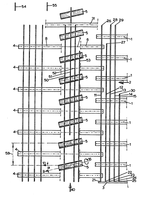
In Fig. 1, chain conveyors 1 together form a
first lateral transfer device for la~eral transfer
of the concrete-reinforcing bars 11,12,13,14,15
lying on it in the direction indicated by arrow 2.
The respective ends 21 to 25 of bars 11 to 15
are laid against stop 3 by a device not shown in the
drawing. The opposite ends of the concrete-
reinforcing bars 11 to 15 not abutting the stop 3
are indicated by 26 to 30 respectively.
The bars 11 to 15 are transferred by the
first lateral transfer device towards a second
lateral transfer device comprising chain conveyors
4.
Except for the foremost one, each chain
conveyor 1 projects in between two chain conveyors 4
of the second lateral transfèr device. In the
overlapping part, chain conveyors 1 and 4 run at the
same vertical height so that the bars 11 to 15
transfer smoothly from the first to the second `
lateral transfer device. Between the chain
conveyors l~ and in front of the foremost chain
conveyor 4 are located circular cylindrical rollers
5 forming a conveyor, which can move the bars both
laterally and longitudinally. The direction of the
rotational a~is of each roller 5 indlcated by arrow
` 1~3~21
13,
9 forms a non-zero angle a with the lateral
direction, indicated by arrow 10, of the second
lateral transfer device.
The axis of each of the rollers 5 lies in the
horizontal plane. The chain conveyors 4 run
horizontally in the part indicated by 6 and at the
same height as the chain conveyors 1 and at the same
height as the topside of the rollers 5. The part 7
of the chain conveyors 4 runs below the underside of
~` 10 the rollers 5. The part 8 of the chain conveyors 4
. . .
runs horizontally again and at $he same height as
the topside of the rollers 5.
The rollers are rotated by conventional drive
means not shown in the drawing in the direction
indicated by arrow 16.
A pick-up device 31 is positioned in front of
the foremost roller 5. This pick-up device is not ~
` shown in further detail but may be the same as in ~ ;
the known sorting apparatus described above and may
comprise a pick-up chain which runs as an arch
.J .. ..
) across a bridge spannlng over the conveyor. The
I chain is provided with pick-up elements for picking
.. ~.
up and conveying in lateral direction an end part of
a bar. Furthermore, the chain is provided with -~-~
blocking means to block in the longitudinal
:; , ,
~33~32~
14.
direction indicated by arrow 40 an end part of a bar
picked up by the pick-up device.
For the sake of clarity the concrete
reinforcing bars 11 to 15 are drawn separated from
one another. In practice the bars may lie touching
one another. By giving the chain conveyors 4 a
slightly higher speed than the chain conveyors 1, a
small separation of the bars from one ano~her takes
, place in the overlapping part of the two chain
conveyors.
The bars which are now slightly separated
from one another are carried towards the rollers 5
by means of the parts 6 of the chain conveyors 4.
~¦ As a result of the angle a of the axis of the
J 15 rollers 5, the bars are subjected by the rotating
``' rollers to both a lateral force in the direction
~ indicated by arrow 10 and to a longitudinal force in`~ the direction indicated by arrow 40.
In the vector diagram of Fig. 2 the speed
vector of a freely moving bar is indicated by arrow ;
41. This speed vector has a longitudinal direction
~ component 42 and a lateral direction component 43.
! By suitable selection of the configuration of the
conveyor and suitable selection of the rotation
speed of the rollers 5 and the speed of the chain
'~ :
.~ .
13~3~1
15.
conveyors 4, the lateral velocity of the bar on the
conveyor may be made equal to the iateral velocity
of the second later~l transfer device.
Bars which are fed in by the chain conveyors
1 are conveyed by the parts 6 of the second lateral
transfer device towards the conveyor with the
rollers 5. Bars of the desired length, such as bars
50 and 52, are picked up by the pick-up elements of
the transfer device 31 and blocked by its blocking
means in the longitudinal direction 40. This means
that these bars make only a lateral movement and
come onto the part 8 of the second lateral transf`er
device, which part carries them further on towards
-: ~
an adjoining processing unit not shown in the
drawing.
. .: . .
Shorter residual part bars, such as the bars
51 and 53 are not picked up by the transfer device
, ~, . :.~: ,,
31 and are given both a longitudinal velocity as ~ ~
; ., . :, .
well as a lateral velocity by the rollers 5. As a
result, these bar parts travel in the direction
: .::
indicated by arrow 41 (Fig. 2). The residual bar
parts then pass under the bridge of the transfer
devlce 31. In Fig. I the residual bar part 51 has
already partially passed the transfer device;
residual bar part 53 is still lying In its original
~33~
16.
position in the longitudinal direction. The
residual parts pass completely through the bridge,
bu~ because they also have a lateral velocity, they
are separated from the bars of desired length and
set down on the same side of the conveyor. 54 and
55 indicate two separated residual bar parts. The
separated residual bar parts are carried off for
further processing by a device not shown in the
drawing.
Fig. 3 gives an isometric view of a part of
the apparatus of Fig. 1. The same numbers from Fig.
1 indicate the corresponding elements in this
figure. Fig. 3 shows that the transfer device 31 `~
has picked up bars 50 and 52 by their forward ends
56 and 57, while these bars are still Iying
partially on the conveyor. The transfer device
conveys the foremost part of these bars laterally.
The residual bar part 51 has already partially ;~;
passed under the bridge of the transfer device, and
the residual bar part 53 is still lying in its
original position in the longitudinal direction. ;
In this embodiment of the invention the
diameter of the rollers 5 is 310 mm, the centre-to-
centre distance of the rollers 5 is 1500 mm, and the
lateral velocity of the bars in operation is 0.15
~3~3~
17.
m/sec, and the longitudinal velocity 2.55 m/sec. As
indicated above, the angle a is 3.4.
Fig. 4 shows a roller 5 having~ as is
preferred according to the invention, a helical rib
60, of pitch 5 cm and height 0.5 cm, on its
cylindrical surface. This rib 60 acts as a braking
means to stop the bars rolling along the roller 5,
and is preferably present only at the end of the ;~
roller adjacent the second lateral transfer device
::.:
' ' ~ ~' ~ '''
~" .
~.
- '