Note: Descriptions are shown in the official language in which they were submitted.
/~
133~
PRE-SLIT INJECTION SITE AND TAPERED CANNULA
Field of the Invention
The invention pertains to coupling systems usable
to transfer materials from one flow conduit to another.
More particularly, the invention pertains to two-part
coupling members wit~ a first part including a pre-slit ~
septum and a second part including a blunt cannula. The -
pre-slit septum slidably receives the blunt cannula to
effect the coupling.
~ 10 Backaround of the Invention
-~ Injection sites usable with pointed cannulae have ~-
long been known. For example, such sites can be formed
with a housing having a fluid flow path therein. A
septum is positioned in the housing closing the fluid
OW pa~n.
- one injection site usable with a piercing cannula
is disclosed in U.S. Patent No. 4,412,573 to Zdeb
entitled "Injection Site." The Zdeb patent is assigned -;~
to the assignee of the present invention.
The pointed cannula can be forced through the
septum into fluid fIow communication wi~h the flow path
; in the housing. Known injection sites usable with a -~
piercing cannula can be physically damaged by repetitive
piercing caused by the sharp cannula. This damage,
known as coring or laceration, can result in subsequent
leakage.
,-~
r~
-- i33 ~ ~2
--2--
Due to problems associated with infectious
agents, personnel using such pointed cannulae do so
with great care. Notwithstanding careful and prudent
practice, from time to time, accidents do occur and
individuals using such pointed cannulae jab
themselves.
Injection sites usable with a blunt cannula
are also known. For example, U.S. Patent No.
~ 4,197,848 issued to Garrett et al. entitled "Closed
¦ 10 Urinary Irrigation Site" and assigned to the assignee
of the present invention discloses one such injection
site. That injection site is a relatively low
pressure device having a relatively thin, molded,
~ sealing member. The sealing member has an opening
¦ 15 therethrough.
A blunt cannulae can be forced through the
sealing member placing the cannulae into fluid flow
communication with a fluid flow pathway in the
injection site.
Injection sites of the type noted above
usable with a blunt cannula have the advantage that
the blunt cannula will not pierce the skin of a
~- user. On the other hand, it is important that the
pre-slit injection site reseal with enough force that
fluids do not ooze therefrom and that airborne
particulate matter, bacterial or viral matter do not
enter therethrough.
Hence, there continues to be a need for a
pre-slit injection site which can be used with a
variety of solutions and over a range of fluid
pressures. Further, there continues to be a need for
such a pre-slit injection site which will reliably
reseal even after many insertions of the blunt
cannula.
~33~
Such an injection site should be able to
receive a large number of insertions of the cannula
without displaying reseal failure. Such an injection
site should provide for improved alignment of the
cannula on insertion. Improved alignment will result
in less chance of damage to the injection site after
repeated insertions of the cannula. Preferably, the
injection site would also be usable with a pointed
cannula. Preferably, a pre-slit injection site
usable with a blunt cannula will provide a reasonable
level of insertion force such that health care
personnel will readily be able to insert the blunt
cannula, yet the cannula will not easily fall from or
I drop out of contact with the septum.
¦ 15 Summary of the Invention
! In accordance with the invention, an easily
wipeable injection site usable with a blunt cannula
is provided. The injection site includes a housing
which defines a fluid flow channel therethrough. The
housing has a first and a second end.
A flexible sealing member is carried by the
housing for sealing the first end. The sealing
member has a resealable opening therein. The sealing
member also iæ formed with a curved exterior -
25 peripheral surface such that the blunt cannula can be ~
sealingly inserted through the opening and placed in ;
fluid flow communication with the flow path.
Further, the blunt cannula can be removed from the
opening with the sealing member then interacting with
the housing so as to reseal the opening.
; The housing can also be formed with the
-~ first end including an annular channel underlying the
sealing member. The sealing member is subjected to
radially directed forces by a tapered surface of the
~,~
. -
133~12
-4-
first end of the housing. These forces tend to
reseal the opening in the sealing member.
The sealing member can be a cylindrically
shaped rubber member. The first end of the housing
can include an interior tapered surface for receiving
the sealing member and for applying the radially
directed forces to the sealing member.
~ A retaining member carried by the first end
i of the housing can be used to retain the sealing
member within the housing. The retaining member can
be generally U-shaped. Alternately, the retaining
member can be formed as a coiled spring.
The retaining member applies axially
directed forces to the sealing member. In one
13 15 embodiment of the invention, the retaining member
deflects the sealing member and forms a curved
exterior peripheral surface thereon. The curved
exterior peripheral surface is an easily wipeable
surface.
The retaining member deflects or distorts
~;~ the upper and lower peripheral edges slightly as a
result of applying axial forces thereto. When the
.~ blunt cannula is inserted into the slit in the
sealing member, an annular interior peripheral region
of the sealing member deforms further and fills, at
least in part~ the annular channel.
~;~ Deformation of this annular peripheral
~; region results in an insertion force in a range of
2.0 to 5 pounds. Preferably, the insertion force
will have a value of the order of 2.0 pounds.
The resealable opening in the sealing member
can extend entirely through that member.
Alternately, the resealable opening can extend only
partway therethrough. In this embodiment, the end of
;}`
1330~12
--5
the blunt cannula will be used to tear through the
remainder of the sealing member.
The sealing member can be formed in two
parts. An exterior cylindrical portion can be slit
S completely. An interior cylindrical unslit portion
can be provided to seal the site until the blunt
~, cannula is inserted therethrough the first time.
The interior surface of the first end can be
formed with the taper in a range on the order of 5
10 degrees to 20 degrees. Preferably, the interior
3 surface will have a taper on the order of 12
degrees. This tapered surface permits the use of a
cylindrically shaped sealing member.
To provide for leak-free insertion, the
15 length of the slit in the sealing member must be less
than one-half the circumference of the cannula being
inserted therethrough. ~ence, the slit length may
exceed the diameter of the ~annula being inserted. -
In addition, the slit length must be great enough,
20 given the elastic limit of the sealing member, to
prevent tearing during insertion.
Further in accordance with the invention, a
coupling system for coupling first and second fluid
flow members together is provided. The coupling
25 system includes an injection site which is affixed to
the first fluid flow member. The injection site
includes a housing. The housing has a fluid flow
path therethrough.
A sealingjmember is carried by the housing.
30 The sealing member has a resealable opening therein.
-~ An annular retaining member is carried by
the housing and cooperates with the housing to retain
the sealing member therein. Radially directed forces
-~ are applied to the sealing member by the housing,
~ 35 thereby urging the opening into a resealed condition.
. ~ ' ~
. ~
~
",:
~ ~33~4~2
A blunt cannula, affixed to second fluid
flow member, has a fluid flow path therethrough. The
cannula carries a locking member for lockingly
engaging the housing when the cannula extends through
the opening of the sealing member. When so
positioned, the two fluid flow members are placed
into fluid flow communication.
The locking member can include a luer-type
twist lock fitting. Alternately, the locking member
can include slidably engageable members which are
responsive to axial movement of the injection site
and the cannula toward one another.
In accordance with further aspects of this
invention, the blunt cannula may be provided with
- 15 features that facilitate insertion into the injection
site, enhance fluid flow or dispersion, increase tug
resistance, and reduce kickback.
In particular, one embodiment of the cannula
includes a tube with a plurality of elongate
discharge slots adjacent the distal end. The fluid
changes direction as ît passes laterally through the
slots and out of the tube. The flow area of the
slots exceeds the flow area inside the tube. This
slot structure enhances fluid flow and dispersion
25 characteristics. In addition, the slots decrease the ~-
contact surface area on the tube exterior so as to
facilitate insertion.
In a further modification, the cannula ~;
includes a lead post on the tube distal end to guide
the cannula through the slit in the injection site.
~ In another cannula embodiment, the tube is-~ generally cylindrical and the fluid discharges
directly from an open end of the tube. The exterior
surface of the tube is provided with grooves to
~; 35 reduce the contact surface area.
.~
".~'~
., ~
.
:,`":~
~33~12
In still another cannula embodiment, the tube has a
J cylindrical portion and a tapered distal end portion
j which are each about equal in length. The taper
'~ facilitates insertion, and the remaining cylindrical
portion reduces kickback.
, In yet another embodiment, the cannula includes an
annular barb which functions to reduce kickback.
Other advantages of a blunt plastic cannula in
accordance with the invention, relative to conventional
steel needles include a higher fluid flow rate capacity
and a simpler one-piece plastic design.
~ Other aspects of this invention are as follows:
;~ A cannula and in~ection site in combination
comprising:
an injection site having a housing defining a fluid
flow path therein, having a penetrable sealing means for
sealing said housing and a retaining means for
maintaining said sealing means in said housing;
a cannula having at least one tube defining a fluid
flow path therein, said tube extending through said
sealing means to establish a sealed fluid flow
connection with said injection site, said tube having a
blunt distal end region extending beyond said injection
site and having a tapered surface on said distal end
region; and
said tube defining in said distal end region a
plurality of elongate slots oriented parallel to said
fluid flow path, each slot extending from said flow path
to the exterior of said tube thereby decreasing the
exterior contact surface~area of said tube and accom-
modating a lateral discharge of fluid from said tube.
~ A cannula and injection site in combination
:.
.~, A';; comprising:
~`1 ~ an injection site having a housing defining a fluid
!`. ~`' 35 flow path therein, having a penetrable sealing means for
;~
,,, :~
~~b
`:~
133~ 2
~ 7a
~ealing said housing and a retaining means for
maintaining said sealing means in said housing;
a cannula having at least one tube defining a fluid
flow path therein, said tube extending through said
æealing means to establish a sealed fluid flow
connection with said injection site, said tube having a
blunt distal end region extending beyond said injection
site and having a tapered surface on said distal end
region; and
said tube having a generally cylindrical region
merging with said tapered distal end region, said
cylindrical region being received within said sealing
means to provide reduced kick back and to provide
increased tug resistance.
A cannula and injection site in combination
comprising:
an injection site having a housing defining a fluid
I flow path therein, having a penetrable sealing means for¦ sealing said housing and a retaining means for
maintaining said sealing means in said housing;
: a cannula having at least one tube defining a fluid
I flow path therein, said tube extending through said
: sealing means to establish a sealed fluid flow
connection with said injection site, said tube having a
blunt distal end region extending beyond said injection
site and having a tapered surface on said distal end
region; and
: said tube having an annular barb received within
: said sealing means to provide reduced kick back and to
provide increased tug resistance.
A cannula and injection site in combination
comprising:
~1: an injection site having a housing defining a fluid
flow path therein, having a penetrable sealing means for
~ sealing said housing and a retaining means for
- maintaining said sealing means in said housing; ~ .
;~
~ ."
~ 1330~i~
a cannula having at least one tube defining a fluid
flow path therein, said tube extending through said
sealing means to establish a sealed fluid flow
connection with said injection site, said tube having a
blunt distal end region extending beyond said injection
site and having a tapered surface on said distal end
region; and
said tube defining in said distal end region a
plurality of grooves in the tube sur~ace oriented
parallel to the flow path to decrease the exterior
contact surface area of the tube.
Numerous other advantages and features of the
present invention will become readily apparent from the
following detailed description of the invention and the
embodiments thereof, from the claims and from the
accompanying drawings in which the details of the
invention are fully and completely disclosed as a part
of this specification.
Brief Descri~tion of the Drawinas
Figure 1 is a side elevational view, partly in
section, of a prior art pre-slit injection site and an
associated blunt cannula;
Figure 2A is a view in perspective of a catheter
` positioned in the hand of a patient with a pre-slit
injection site in accordance with the present invention
positioned adjacent thereto;
Figure 28 is a perspective view of the catheter of
Figure 2A with a pre-slit injection site in accordance
. ~ with the present invention rotatably affixed thereto;
Figure 3 is an enlarged side elevational view in a
~: section of a pre-slit injection site in accordance with the present invention formed on a
. I ~ ~ ~ 7
;~
'~
r
~ - 1330~12
-8-
body having a luer twist-lock type connector for
coupling to a catheter;
Pigure 4A is an exploded view of a pre-slit
injection site, a shielded blunt cannula and a
, 5 syringe prior to being coupled together;
i~ Figure 4B is an enlarged, side elevational
3 view in section of the pre-slit injection site, the
shielded blunt cannula and the syringe of Figure 4A
coupled together to form a sealed fluid flow system;
Figure 5A is a view in perspective of a
pre-slit injection site prior to engaging a blunt
cannula carrying a locking member;
Figure ~B is an enlarged side elevational
view, partly broken away, illustrating the
interrelationship between the pre-slit injection site
and the blunt cannula of Figure SA;
Figure 6 is an overall view of a container,
an associated solution administration set and a
pre-slit injection site in accordance with the
present invention;
Figure 7 is an enlarged side elevational
view, partly broken away illustrating the
relationship between selected elements of Figure 6;
Figure 8 is a side elevational view, partly
broken away illustrating an alternate shielded
cannula in accordance with the present invention;
Figure 9 is a side elevational view, partly
in section, of a pre-slit injection site mounted on a
. : fragment of a solution container;
: 30 Figure 10 is a side elevational view of a
~: fragment of a solution container carrying, as a
single port, a pre-slit injection site;
. ~:: Figure 11 is a side elevational view of the
injection site and the fragmentary container of
Figure 10 prior to being engaged with a shielded
. ~ cannula carried by a syringe;
,:
~;~ ~: :
~33~2
g
Figure 12 is an enlarged side elevational
view, partly in section, of a coupling system with a
pre-slit injection site partly coupled to a blunt
cannula;
Figure 13 is an enlarged side elevational
view, partly in section, of the coupling system of
Figure 12 subsequent to engagement of the two
coupling members
Figure 14 is a side elevational view, partly
broken away, of a spike connector carrying a pre-slit
injection site in accordance with the present
invention;
Figure 15 is an enlarged side elevational
view of a Y-connector in section carrying a pre-slit
injection site in accordance with the present
invention;
Figure 16 is an enlarged fragmentary side
elevational view in section of a coupling member
carrying a pre-slit injection site where the slit
~ 20 extends only partway through the septum;
: Figure 17 is a perspective view of a burette
: solution administration set carrying a pre-slit ::
injection site in accordance with the present
invention;
: 25 Figure 18 is a view of part of a burette
solution administration set carrying a pre-slit
~ injection site being coupled to a shielded blunt ~.
: cannula;
.Figure l9 is a step in the method of making
:~ 30 a pre-slit injection site in accordance with the
present inventionî :
Figure 20 is another step in the method of
~: making a pre-slit injection site in accordance with
~ the present invention;
- 35
:
`~,
..
,~
~ .
~ i33~2
--10--
Figure 21 is an initial phase of a final
step in making a pre-slit injection site in
accordance with the present invention;
Figure 22 is an intermediate phase of the
S final step in a method of making a pre-slit injection
site in accordance with the present invention
Figure 23 is a final phase of the final step
in a method of making a pre-slit injection site in
accordance with the present invention
Figure 24 illustrates an initial phase in an
alternate step of making a pre-slit injection site in
accordance with the present invention;
Figure 25 illustrates a final phase of the
I alternate step in a method of making an injection
,~ 15 site in accordance with the present invention;
Figure 26 illustrates yet another alternate -
step in a method of making a pre-slit injection site
in accordance with the present invention; ;
Figure 27 is an enlarged, fragmentary
. 20 cross-sectional view of another embodiment of an
injection site in accordance with the present
: invention;
Figure 28 is a cross-sectional view taken
generally along the plane 28-28 in Figure 27;
Figure 29 is an end view of another
embodiment of the cannula in accordance with the
present invention;
Figure 30 is a cross-sectional view taken -
generally along the plane 30-30 in Figure 29;
Figure 31 is an end view of another
embodiment of the cannula in accordance with the :;
~ present invention;
.~ Figure 32 is a cross-sectional view taken
Y'~ generally along the plane 32-32 in Figure 31;
~` ~330~2
Figure 33 is a cros.s-sec~.onal -~iew taken
generally along the plane 33-33 in Figure 32;
Figure 34 is an end view of another
embodiment of the cannula in accordance with the
present invention;
Figure 35 is a fragmentary, side elevational
view of the embodiment of the cannula illustrated in
Figure 34;
Figure 36 is a cross-sectional view taken
generally along the plane 36-36 in Figure 34;
¦ Figure 37 is a cross-sectional view taken generally along the plane 37-37 in Figure 36;
Figure 38 is an end view of another
embodiment of the cannula according to the present
15 invention; ~-
Figure 39 is a cross-sectional view taken ~:-
generally along the plane 39-39 in Figure 38; .
Figure 40 is a cross-sectional view taken
generally along the plane 40-40 in Figure 39; ~.
Figure 41 is an end view of another
; embodiment of the cannula according to the present invention;
:~ Figure 42 is a cross-sectional view taken
generally along the plane 42-42 in Figure 41;
Figure 43 is an end view of another .
embodiment of the cannula according to the present
invention;
Figure 44 is a cross-sectional view taken
:~ general~y along the;plane 44-44 in Figure 43; and
: 30 Figure 45 is a view in section of another
insertion member for a blunt cannula.
: Detailed Description of the Preferred Embodiments :::
While this invention is susceptible of ~-
~` embodiment in many different forms, there are shown ~;
î,~ 35 in the drawing and will be described herein in detail
.~
.. ~'~
~3~0 ~2
-12-
specific embodiments thereof with the understanding
that the present disclosure is to be considered as an
exemplification of the principles of the invention
and is not intended to limit the invention to the
specific embodiments illustrated.
A prior art pre-slit injection site 10 and
associated blunt cannula 12 are illustrated in Figure
1. The prior art injection site 10 has a cylindrical
housing 14 with a fluid flow path 16 therethrough. A
first end 18 of the housing 14 is closed with a
relatively thin disc-shaped resealable member 20.
The member 20 has a resealable opening 22 therein.
The member 20 is a molded septum with an
integrally formed skirt 20a. The skirt 20a is
oriented generally perpendicular to the portion of
the septum with the opening 22.
The cannula 12 includes a body portion 24
which carries at a first end a hollow, cylindrical,
blunt piercing member 26. As the cannula 12 is m~ved
in a direction 28 toward the first end 18 of the
: injection site 10, the member 26 slidably engages the
opening 22. The sealing member 20 is then deformed
adjacent the opening 22 and the member 26 extends
: into the flow path 16. A fluid flow path through the
cannula 12 will then be in fluid flow communication
~: with the flow path 16 via the hollow piercing member
: 26.
In contradistinction to the prior art
: pre-slit.injection site. 10 of Figure 1, Figures 2A
~: 30 and 2B illustrate a pre-slit injection site 34 being
~; coupled to a peripheral venous catheter 36. ~he
catheter 36 is shown in fluid flow communication with
a vein in a hand H of a patient. The catheter 36
carries at a proximal end 38 a luer-type female twist
~:~ 35 lock connector 41.
....
,~
- 133~17
-
-13-
The pre-slit injection site 34 is formed
with a cylindrical housing 40 having a first end 42
and a second end 44.
Carried by the housing 40, adjacent the
~ 5 second end 44 is a hollow cylindrical fluid flow
; member 46. The member 46 slidably engages a
~ receiving member in the housing 38 of the catheter
¦ 36, thereby providing a sterile fluid flow coupling
as is well known and conventional.
A plurality of internal male luer-type
threads 48 is carried by the housing 40 adjacent the ;
second end 44. The threads 48 will engage the flange
member 41 when the injection site 34 is rotated in a
direction 50. When so coupled together, the catheter
36 and the injection site 40 provide a sealed
coupling through which fluids may be injected into
the vein of the hand H.
Figure 3 illustrates, in section, further
details of the injection site 34. A resealable
septum 52 is carried by the first end 42 of the
housing 40. The septum S2 includes first and second
spaced apart surfaces S4 and S6 respectively. The ~
surface 54 has been forced into a dome-like shape by ~ ;
annular, U-shaped, swaged end members 58 carried by
the first end 42. The dome-like shape of the surface
54 can extend beyond a surface 42a of the first end
42. This facilitates cleaning the surface 54.
The septum 52 has a generally cylindrical
~ shape. The septum S2 can be formed of a latex or
synthetic rubber material. Alternately, the septum
can be formed of a thermoplastic elastomer. The
material used for the septum S2 should be non-toxic
and sterilizable such as by means of radiation, steam
or EtO.
'; -
`:::
,~
,~ ~
- 133041~
~.
Because the septum 52 is generally
cylindrical in shape, it can be die-cut from a sheet,
cut from an extruded rod or molded. The septum 52
can have an exemplary diameter on the order of .30
5 inches. The height of the septum 52 can be, for
example, on the order of .125 inches.
The first end 42 is also formed with a
tapered interior surface 60 which terminates in an
annular channel 62~ The tapered interior surface 60
has a taper in a range of 5 degrees to 20 degrees.
Preferably, the taper will be on the order of 12
degrees. With the indicated size of the above noted
exemplary septum 52 and a 12 degree taper, diametric
resealing compression of the septum 52 adjacent the
channel 62 is on the order of 10%.
The channel 62 is bounded in part by a
septum supporting ridge 62a. The channel 62 can
typically have a depth in a range of .050-.070 inches.
A peripheral surface 64 of the septum 52
slidably engages the tapered interior surface 60 as
the septum ~2 slides into the first end 42. The
annular channel 62 which underlies the interior
peripheral surface 56 of the septum 52 is provided to
permit the septum 52 to deform when a blunt cannula
is inserted through an opening 66 therein.
The housing 40 is also formed with a fluid
flow path 68 such that fluids injected via a blunt
cannula inserted through the resealable opening 66
can flow into the catheter 36 for delivery to hand
of the patient.
he swaged end members 58 apply axial forces
to the septum 52 thereby creating the domed exterior
peripheral surface 54. The axial forces applied by
the end members 58 slightly deform the regions 52a
and 52b. In contradistinction, the tapered internal
: :
13304~2
surface 60 applies radially directed forces to the
septum 52, thereby forcing the opening 66 into a
resealed condition.
~ n an alternate embodiment, the surface 52
could be formed as a flat, as opposed to a domed,
surface.
Once the injection site 34 is lockingly
engaged with the catheter 36, a sealed system is
formed through which fluids can be infused into the
catheter 36. The resealable septum 52 closes the
fluid flow path 68.
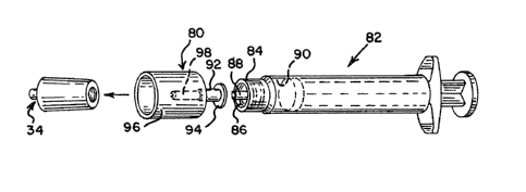
Figures 4A and 4B illustrate in combination
the injection site 34, a blunt shielded cannula 80
and a syringe of a conventional type 82. The syringe ~;
15 82, as is well known, can be formed with a '
cylindrical hollow end 84 which carries a male ; ;
luer-type twist lock thread 86. A hollow centrally
located cylindrical fluid flow member 88 is in fluid
flow communication with an interior region 90 of the
syringe 82.
~ The shielded blunt cannula 80 carries at a
- first end 92 a female luer twist-lock flange 94. The
flange 94 will slidably engage the threads 86 of the
end 84. Hence, the shielded blunt cannula 80 can be
locked to the syringe 82 forming a closed fluid flow
pathway. The shielded cannula 80 could alternately
be formed fixedly attached to the syringe 82.
The shielded blunt cannula 80 carries a
cylindrical hollowiprotective shield 96 wh,ich
surrounds a centrally located hollow, elongated
cylindrical blunt piercing member 98. The
~ cylindrical blunt piercing member 98 has a total
,~ length on the order of 3 times the thickness of the
septum 52 in order to ensure complete penetration.
~ 35 The cylindrical blunt piercing member 98 has a
'~
~ ,
/~
~ ~33~4~2
-16-
diameter on the order of 1/3 the diameter of the
septum 52. The shield 96 is desirable and useful for
maintaining the piercing member 98 in an aseptic
condition by preventing touch contamination prior to
the shielded cannula 80 engaging the pre-slit septum
52. Also, the shield helps to align the piercing
member with the pre-slit septum.
~he cylindrical blunt piercing member g8 can
slidably engage the pre-slit septum 52, best
~ 10 illustrated in Figure 4B, thereby extending through
¦ the preformed openiny 66 therein. As illustrated in
Figure 4B, when the piercing member 98 slidably
engages and pierces the septum S2, the region 52a
deforms by expanding into and filling, at least in
15 part, the annular channel 62.
~ The deformation facilitates insertion of the
3 piercing member 98 through the slit 66. Subsequent ~-
to the piercing member 98 slidably engaging the
injection site 34, the interior region 90 of the
20 syringe 82 is in fluid flow communication with the
flow path 68 of the injection site 34 via flow paths
88a and 98a respectively of the syringe and the blunt
piercing member 98.
In this engagement condition, the septum 52
25 seals completely around the piercing member 98.
;~ Hence, exterior gases, liquids or airborne matter
will be excluded from the channel 68.
Subsequent to infusing fluid from the
syringe 82 into the fluid flow pathway 68,j hence into
30 the catheter 36 and the hand ~ of the patient, the
syringe 82 with lockingly engaged shielded cannula 80
~; can be slidably withdrawn from the injection
site 34. Subsequent to this withdrawal, the septum
~; 52 reseals the opening 66 therein.
~ ~:
~ .
.~
. . .
133~412
-17-
The opening 66 will repeatedly reseal, when
the piercing member 98 is removed, provided that the
pressure (in the septum 52 of the opening 66) created
by interaction of the septum material properties and
compression supplied by the housing exceeds the
pressure challenge of the fluid contained within.
Blunt cannula do not haphazardly core, lacerate, or
I otherwise damage the sealing interface 66 as ~--
I conventional needles do, thereby allowing repeatable
resealability. ~owever, septum material properties,
thickness, and compression allow resealability for a
finite number of conventional needle insertions. The
~ combination injection site 34 and catheter 36 then
j return to its pre-infusion, sealed condition.
j~ 15 Figures 5A and 5B illustrate the pre-slit
injection site 34 used in combination with a blunt
cannula 80a. The cannula 80a includes a hollow body
portion 92a with a Luer flange 94a, a piercing member
98a, and manually operable elongated locking members
lOOa and lOOb. Alternately, a tubing member could be
affixed to the hollow body portion 92.
Curved end regions lOOc of the members lOOa
and lOOb slidably engage the second end 44 of the
housing 40 when the piercing member 98a of the blunt
cannula 80a has been forced through the pre-formed
opening 66, best illustrated in Figure 5B. The
embodiment illustrated in Figures 5A and 5B has the
advantage that the infusing cannula 80a cannot
~ accidentally disengage from the pre-slit septum 34
; 30 during the fluid infusion process. It will be
- ~ understood that while spring-like deflecting members
~`~; lOOa and lOOb are illustrated in Figures 5A and 5B
~ that other forms of locking members are within the
;~ spirit and scope of the present invention.
~ 35
:~
, ~
133~2
-
-18-
; Figure 6 illustrates an alternate pre-slit
injection site 34a. ~ tubing member 102 can be
fixedly attached to the cylindrical hollow fluid flow
' member 46. The embodiment 34a of Figure 6 utilizes
the same structure for the septum 52 including the
tapered surface 60 and the underlying annular channel
62 as does the embodiment 34 in Figure 3. The
shielded cannula 80 can be utilized with the
injection site 34a as previously described.
In the event that it is desirable to infuse
~ solution from a container 104 with a conventional
¦ port 106, a fluid administration set 110 of a
conventional variety may be utilized. The set 110
~ includes a spike connector 112 at a first end. The
i 15 spike connector 112 is designed to pierce the port
106 of the container 104. The set 110 can also carry
a slidably engageable connector 114 of a known type
at a second end. As illustrated in Figure 7, the
connector 114 can slidably engage the hollow
cylindrical member 92 of the shielded cannula 80,
thereby placing the interior fluid of the container
104 into fluid communication with the tubing member
102.
Figure 8 illustrates yet another alternate
80b to the shielded cannula 80. ~he piercing member
98 carries a tubing member 118 fixedly attached
thereto. ~he tubing member 118 could be coupled at a
second end to a container such as the container 104.
The present pre-slit injection site can be
directly affixed to a container 120 as illustrated in
Figure 9. The container 120 includes a rigid hollow
~; cylindrical access port 122 affixed thereto. The
access port 122 includes a fluid flow channel 124 in
fluid flow communication with the interior of the
container 120. Sealingly affixed to the port 122 is
` a pre-slit injection site 126.
,~
~ .
1 3 ~ 2
--19--
j The site 126 includes a cylindrical housing
. 128 which carries at a first end 130 a septum 132
. with a slit 134 formed therein. The first end 130
has been s~aged to form an annular U-shaped retaining -
member 136. The retaining member 136 in turn forms a
domed exterior peripheral surface 138 on the septum
132.
~ The first end 130 also includes a tapered3 interior force applying surface 140 and an annulari 10 channel 142 underlying the septum 132. As discussed
I previously, the channel 142 provides a space into
i, which the septum 132 can deform when a blunt cannula
. is forced through the resealable opening 134.
¦ Further, as illustrated in Figure 9, the
lS injection site 126 can be covered by a removable
cover 146 of a type used with the conventional port
106 of the bag 104. :-
While the bag 120 is illustrated formed with
~; two ports, the conventional pierceable port 106 and
; 20 the pre-slit injection site 126, it will be
understood that as an alternate (Figure 10), a
: container 150 could be formed which includes only the
pre-slit injection port 126. The removable cover 146
~;~ could be used in combination with the container 150.
As illustrated in Figure 11, the pre-slit :
injection site 126 can be utilized for the purpose of
injecting fluid from the syringe 82, coupled to the ~;
shielded cannula 80, into the container 1~0. When so :
utilized, the blunt piercing member 98 is used to
place the interior fluid containing region 90 of the
: syringe into fluid flow communication with the
;-~ interior of the container 150.
Figures 12 and 13 illustrate a fl~id flow
coupling system 151 having as a first element a
pre-slit injection cite 126a. The site 126a is ehe
.~
~3304~2
-20-
same as the site 126 except for a plurality of
exterior threads 153 formed on an exterior peripheral
surface 155 of the housing 128a. A second element of
the coupling system 151 is a shielded ~lunt cannula
157.
The shielded blunt cannula 157 is sealingly
affixed to a flexible tubing member 159 ~y means of a
proximal hollow cylindrical member 161. The member
161 extends into a hollow cylindri~al s~ield 163 to
form a blunt piercing member 165.
The shield 163 carries, on an interior
peripheral surface, a set of coupling threads 165
The threads 165 match the threads 153.
The two connector elements 126a and 157
slidably engage one another when the shielded cannula
~ 157 moves in an axial direction 167 toward the
i iniection site 126a. The blunt pi~rcing member 165
penetrates the septum 132a.
The coupling member 157 ~an then be rotated
- 20 in a direction 169 such the interior set of threads
165 carried thereon engages the exterior set of
threads 153. As a result, the two coupling members
126a and 157 are lockingly engaged ~Qge~her with the
insertion member 165 extending through the opening
134a in the septum 132a. Hence, fluids ~an flow from
the container 150a via the connector system 126a and
157 through the tubing member 1~9 to ~he recipient.
Injection sites of the typ~ described above
are also usable inlconnection with other fluid filow
coupling components. For example, with respect to
Figure 14, a pre-slit injection site 160 of the type
described above can be used in combination with a
spike connector 162 of a conventional variety. Spike
connectors such as the spike connector 162 can be
35 used to pierce conventional pnrts su~h as the port --~
~ `
`~ 1 3 3 ~
-21-
106 of the container 104 (Figure 6). When the spike
connector 162 is so used, the pre-slit injection site
160 can then be utilized for the purpose o~ coupling
to other fluid administraticn sets.
The injection site 160 illustrates an
alternate form of swaging the first end 42c for the
purpose of retaining the septum 52c therein. The
first end 42c can be swaged so as to form an
annularly shaped, spiral, spring-like member 164.
The member 164 has a free end 164a which engages the
exterior dome-shaped peripheral surface 54c of the
septum 52c. The spiral, spring-like swaged member
164 will tend to uncoil, thereby continuously
applying axial force to the septum 52c and
maintaining the domed exterior peripheral surface 54c.
In yet another alternate, Figure 15
illustrates a pre-slit injection site 166 formed in a
Y-junction member 168. The Y-junction member 168 is
fixedly attached to first and second tubing members
20 170 and 172 respectively.
As an alternate to forming the slit 66d
completely through the septum 52d, as illustrated in
Figure 16, a slit 66e can be formed only partly -
through the septum 52e. Such a structure has the
further advantage that, until used for the first
time, the septum 52e is completely sealed.
The septum 52e can be formed in two parts.
One part can have a slit, such as the slit 66e,
extending entirely therethrough. A second part can ! :
be formed without a slit. These two parts can be
located adjacent one another in the first end 42e of
the injection site.
The slit 66e may be longer on the top of the
septum than the bottom. This feature aids blunt
3~ cannula alignment with the slit upon insertion, and
, ,~
. ~ ~
~. ~
~ 3 ~
aids resealability by minimizing the critical slit
sealing interface area.
In accordance with the present invention,
the slit could have a length with a range on the
order of .03 to .150 inches. Preferably, a slit
length on the order of .07 inches will be used in
combination with a blunt cannula having a diameter on
the order of .1 inches.
When initially used, the blunt cannula
piercing member, such as the member 98, will be
forced through the slit 66a. The lower peripheral
surface 56e will then be punctured, providing access
for the blunt cannula piercing member 98 into the
I fluid flow pathway 68e.
¦ 15 Pre-slit injection sites of the type
described above can be utilized in combination with
burette solution administration sets. One such set
176 is illustrated in Figure 17. The set 176
includes a pre-slit injection site 178 of the type
; 20 described above. The injection site 178 is affixed
to an exterior planar surface 180 of the burette
182. A removable cover 184 can be used to maintain
;~ the injection site 178 in an aseptic condition until
blunt cannula 186 or 188 is inserted therethrough.
Figures 19-23 disclose a method of making a
pre-slit injection site in accordance with the
present invention. In a first step, a housing 200 is
provided. The housing 200 has an interior tapered
surface 202 at a first end 202a thereof. The
interior peripheral surface terminates in an annular
~ channel 204. A cylindrical septum 206 can be
;~ provided adjacent the end 200a.
c~ In a second step, the septum 206 can be
forced into the end 202a of the housing 200 and
3~ slightly deformed by the tapered peripheral surface
.' ' .
,~
' ,;~ '
., ~
i330~2
-23-
202 using an axially moving die 210. When positioned
by the die 210, the septum 206 is located adjace~t an
internal annular ring 212 which bounds the annular
channel 204.
In a third step, a second die 214 can be
utilized to swage the end 200a into spiral-shaped,
spring-like members 200b which apply axially directed
forces against an exterior peripheral surface 206a of
the septum 206. The axially directed forces form the
flat surface 206a into a domed exterior peripheral
surface 206b as illustrated in Figure 23.
Simultaneously, with swaging the end members
200a so as to lock the septum 206 into the housing
200 and to form the domed exterior peripheral surface
206b, a knife 216 can be utilized to form a slit in
the septum 206. Alternatively, the slit may be cut -
by a separate die in a separate step. If the septum
206 is formed as an extrusion, the slit can be
created during the extrusion process. If the septum
20 206 is formed by stamping from a rubber sheet, the ;~
; slit can be cut during the stamping process. If the
septum 206 is formed by compression molding t the slit
can be cut during the trimming process.
In order to extrude the slit into rod, a -
flat pin extrusion bushing can be used. A trailing
ribbon may be attached to the bushing. The ribbon
would prevent curing material across the slit. The
ribbon or wire could be placed in the rod core and
later stripped out leaving a slit. An inert
substance, such as silicone oil, could be coextruded
in the center of the rod to prevent curing across the
slit and provide lubrication and a visible target for
cannula insertion.
Figures 24 and 25 illustrate alternate
~ 35 swaging steps wherein a die 220 moving axially toward
'~:~
:~
:~
~:
~'
1 3 ~
-24-
the housing 200 swages the end region 200a so as to
form an annular U-shaped region 200c and the exterior
domed peripheral surface 206c.
The dies 214 or 220 can be formed with
various alternate shaped swaging surfaces 224, as
illustrated in Figure 26, depending on the precise
shape of the end swage which is desired. It will be
understood that all such variations in the swaging -
operation are within the spirit and scope of the
present invention.
The injection site configuration need not be
limited to the configurations depicted in
Figures 3-5B, 9, 12-16. Rather, several
configurations could be constructed without departing
from the scope of this invention. Any such
configuration would provide a flexible preslit -
sealing member captured in a housing which provides
compression to create a seal against pressure and a
void region to accommodate deformed portions of the
sealing member material only when the material is
deformed or displaced by a blunt cannula piercing
member. One such possible configuration is depicted
in Figures 27 and 28.
~igures 29 and 30 illustrate a tapered
cannula structure 250 which is an alternate to the
tapered cannula 98. The cannula 250 includes a
proximal end 252 with an interior region 254. The
region 254 is in part bounded by an internal
peripheral wall 256 which is formed with a standard
30 Luer taper. The tapered cannula 250 can be formed ~-
with a Luer-type coupling flange 257 at the proximal
~; end so as to be releasably connectable to the syringe
,~
`-~ 82 as was the tapered cannula 98 previously
discus
;,~
,.~i ~ ~
~`- 13304~2
-25-
Extending from the proximal end 252 is a
cylindrical tube having a cylindrical mid-region 258
and a distal end member 260. The member 260 has a
generally elongated, cylindrical shape with an
exterior side wall 262. A centrally located,
cylindrical, internal fluid flow path 264 extends
through the di~tal end member 260 and mid-region 258
in fluid flow communication with the interior region
254.
The distal end of the end member 260 has a
tapered exterior surface 266. The tapered exterior
surface 266 minimizes insertion force as the cannula
250 is being forced through a slit of a septum, such
as the slit 66 in the septum 52. The angle of taper
of the surface 266 is preferably in a range between 1
to 15 degrees.
The member 260 is also provided with a
plurality of elongated grooves 268. The grooves 268
; in the exterior wall of the member 260 decrease the
surface area of contact at the cannula/septum
interface during insertion of the cannula into the
injection site 34. This reduced exterior contact
surface area decreases the frictional component of
the insertion force.
In one embodiment, the tapered blunt cannula
250 may have overall insertion length, corresponding
to combined axial lengths of mid-region 258 and end
member 260, on the order of 0.375 inches.
An alternatel¢annula structure 280 is
illustrated in Figures 31, 32 and 33. The cannula
structure 280 includes a proximal end region 282
corresponding to the end region 252 of the cannula
250. The region 282 includes a Luer flange 283. The
cann~la 280 also includes a central, elongated,
cylindrical region 288.
,,:'.;`~
, ,.~
~:
-
~3304l2
-26-
The central region 288 carries at a distal
end thereof an elongated cylindrical end member 290.
The member 290 includes an exterior, peripheral,
cylindrical surface 292 (Figure 31). The surface 292
is interrupted by a plurality of spaced-apart,
elongated slots or apertures 294. The slots 294 are
defined by first and second spaced-apart, elongated,
parallel side surfaces 294a and 294b. Each of the
slots terminates in an end surface 294c at the
10 central region 288. ;~
A fluid flow path 294d extends through the
cannula 280. The flow path 294d is in fluid flow
communication with the slots 294.
Between the slots 294, at a distal end of
the region 290, the exterior surface 292 terminates
in tapered end regions 298 to facilitate insertion of
the cannula into a pre-slit injection site. The
slots 294 themselves also function to decrease the
surface contact area, and this further minimizes the
insertion force.
The slots 294 are oriented substantially 90
degrees apart around a longitudinal axis 300. The
slots 294 increase the internal flow path ;
~ cross-section. This increases the fluid flow rate.
- 25 The slots 294 also provide for enhanced
-~ dispersion characteristics owing to the fluid flowing
radially out through the slots 294. This radial -~
flow, effecting a change in fluid flow direction of
about 90 degrees, promotes flushing and dispersion of
fluid through the injection site 34.
Another embodiment of a blunt cannula 310 is
illustrated in Figures 34-37. The cannula 310 is
formed with an enlarged proximal connection region
312 corresponding to the region 252 of the cannula
250. The region 312 includes a Luer flange 313 and a
central fluid flow reg~on 314.
- 1330412
-27-
An intermediate, cylindrical region 318
extends from the proximal connection region 312. The
cylindrical intermediate region 318 includes a fluid
flow path 320 in communica~ion with the fluid flow
region 314.
The end region 324 extends from the region
318 and includes a first cylindrical portion 326 into
which the fluid flow path 320 extends. The region
326 terminates in a tapered exterior surface 328.
The tapered exterior surface 328 merges with a
centrally located lead post or guide post 330. The
lead post 330 terminates in a hemispherical end
surface 332.
~ The lead post 330 helps locate the septum
j 15 slit 66 prior to insertion and facilitates
penetration of the septum slit 66 by the cannula.
The lead post 330 facilitates insertion by providing
a very low insertion force at the beqinning of the
insertion step as the cannula is pushed through the
slit, such as the slit 66.
In a preferred embodiment, the guide post
330 can have a length on the order of 0.060 inches
and a diameter on the order of 0.050 inches.
The end region 318 includes a novel
~S structure for increasing the flow rate and enhancing
dispersion characteristics. In particular, the
region 318 includes three radially oriented slots
338. Each slot 338 has sides 339a and 339b which
each lie along a radius of the cylindrical portion
30 326 as best illustrated in Figure 37. The fluid
flowing through the cannula 310 undergoes a change in
~:~
direction (of up to about 90 degrees relative to the
cannula center line 337) in the slots 338. This
change in direction increases fluid dispersion.
Further, since the slots 338 open radially, fluid
P ~
133~4~2
-28-
flow can be maintained even if the end surface 332 of
the cannula is pushed up against any material in the
system in which the cannula is inserted.
Another embodiment of the tapered cannula of
5 the present invention is illustrated in FIGS. 38-40
and is designated generally therein by reference
numeral 340. The cannula 340 includes a proximal end
342 which can include a Luer coupling flange 344 for
cooperating with a suitable mating structure on a
syringe. The proximal end 342 also defines an
interior region 346.
Extending from the proximal end 342 is a
generally cylindrical mid-region 348. Extending from
the mid-region 348 is an end member or region 350
which includes a tapered surface 352.
I The distal end of the end region 352
terminates in a blunt, arcuate end surface 356.
l Defined within the mid-region 348 and end region 350
¦ is an internal fIuid flow channel 354 which
communicates with the interior region 346. Fluid
discharges from the flow channel 354 via grooves or
apertures 358 in the end region 350. The change in
; direction of the fluid flow as the fluid passes from
the interior channel 354 through the apertures 358
improves fluid dispersion with respect to mixing or
flushing in the system downstream of the cannula
(e.g., the injection site, drug vial, etc.). The
apertures 358 may also function to increase
withdrawal force or tug resistance.
Moreover, since the fluid passes radially
out through the apertures 358, fluid flow through the -
~ cannula 340 can be maintained even when the distal
;~ end surface 356 of the cannula is bottomed out or
pushed against any material in the system in which
the cannula is inserted.
,
` . ~'
~ ~ L~
133~ 412
-29-
The structure of the cannula 340 is adapted
to be constructed with a minimal lead post length
(i.e., the portion of the cannula distal end between
the end surface 356 and the interior flow channel
354). Further, the design accommodates the use of a
minimal tip diameter, minimal taper angle, and
minimal cannula diameter. The minimization of these
parameters results in a decrease in the peak
insertion force required to properly install the
cannula in the injection site.
Preferably, the total cross-sectional flow
area through the three apertures 358 is about three
times the cross-sectional flow area of the interior
channel 354. This enhances the flow rate capability
compared with a simple open ended cylindrical flow
channel of equal length.
The design of the cannula 340 also is
effective in reducing or limiting "kick back" or
recoil of the cannula after insertion. The resilient
material of the septum in an injection site can
subject the cannula to forces tending to push the
cannula back out of the septum. The kick back forces ~`
on the cannula 340 are minimized by the provision of
the generally cylindrical mid-region 348.
Another embodiment of the cannula of the
, ~ present invention is illustrated in Figures 41 and 42
!'~ wherein the cannula embodiment is designated
generally therein by the reference numeral 360. The
cannula 360 includes a proximal end 362 defining an
30 interior region 364 and having a Luer flange 366 for
connection to a suitable mating engaging structure.
A generally cylindrical mid-region 366
extends from the proximal end 362, and a end region
368 extends from the mid-region 365. As with the
3S previous embodiment of the cannula 340 illustrated in
.~;
.-~ .
:~
1330~ ~
-30-
Figures 38-40, the embodiment of the cannula 360
minimizes kick back or recoil owing to the provision
of a substantially cylindrical mid-region 366. This
design a~so increases withdrawal or tug resistance.
A generally cylindrical internal flow
channel 370 extends through the end region 368 and
mid-region 366 in communication with the interior
region 364 of the proximal end region 362. The end
region 368 is provided with a tapered surface 372.
The design permits the use of a very small taper to
minimize the insertion force.
Further, the design permits the cannula 360
to be constructed with a small tip diameter, small
taper angle, and small cannula diameter so as to
reduce the peak insertion force.
Another embodiment of the cannula of the
present invention is illustrated in FIGS. 43-44 and ~-
is designated generally therein by reference numeral
380. The cannula 380 includes a proximal end 382
with a Luer flange 384. An interior fluid flow
region 386 is defined on the interior of the proximal
end 382.
Extending from the proximal end 382 i9 a
mid-region 388. A distal end region 390 extends from
25 the mid-region 388. An internal fluid flow channel ~-
or path 392 extends through the end region 390 and
~`~ mid-region 388, and is in communication with the ~-
interior flow region 386.
The end~region 390 has an exterior tapered
surface 394. This facilitates insertion of the
cannula into the injection site. In contrast, the
mid-region 388 is generally cylindrical so as to
,`~ minimize kick back and increase the withdrawal force
or tug resistance.
~ 35
'.~:
,-~
, ~... ,.. ,.. ".. .
1330412
-31-
Further, to provide even greater withdrawal
force, the mid-region 388 includes an annular barb
396. The barb 396 has a sufficient radius so as to
preclude damage to the septum of the injection site
and so as to accommodate molding in a straight-draw
too$. The maximum diameter of the annular barb 396
may typically be on the order of 0.02 inches greater
than the diameter of the cylindrical mid-region 388.
Although the barb 396 functions to prevent
inadvertent removal of the cannula 380 from the
septum of the injection site, removal of the cannula
380 can still be achieved by exerting ~ sufficiently
great axially directed removal force on the cannula
380.
lS Still another embodiment is illustrated in
; Figure 45 which includes a blunt tapered cannula
insertion member 400 for insertion into a pre-slit
injection site, the cannula 400 having a distal end
region 402 with a tapered exterior surface which in
the preferred embodiment is an approximately 8
taper. The defined aperture 404 for fluid flow is
disposed at the end 406 of the distal end region
402. The end 406 includes a radiused tip defined by
, .
a radius of approximately 0.01 inch. The radiused
tip reduces insertion force, assists in locating the
slit in the injection site and in addition has the
lr ,; practical advantage of facilitating complete filling
¦~ of the cannula mold cavity.
The tapered surface of the distal end region
402 has an axial length of approximately O~lOr in the
preferred embodiment. Adjacent to the tapered distal
end region is a generally cylindrical region 408 for
entering into the injection site behind the distal
end region 402, thereby reducing kick back during
~ 3~ insertion. The generally cylindrical region 408 has `~
'' a small draft angle such as about one-half degree.
$ ~;
13304~ ~
32-
The force required to insert any of the
above-discussed embodiments of the blunt tapered
cannula into the septum of the injection site depends
upon a number of factors: friction at the
cannula~septum interface, cannula diameter, cannula
taper angle, and degree of septum compression. The
f cannula/septum interface friction is, in ~urn,
I dependent upon lubrication, if any, material
ff properties, and surface finish. It will be
¦ 10 understood that the friction at the cannula/septum
interface can be reduced by providing a smoother
' surface finish on the cannula (e.g., by sand blasting
f the cannula exterior surface) or by molding the
cannula so as to produce a matte finish. ;
15 Conventional lubricants can also be used to further
reduce the friction and thereby lower the insertion
force required.
In the embodiments of the cannulae described
; herein, the mid-region and the tapered distal end
20 region may be alternatively characterized as together
forming at least one tube defining a fluid flow path
therein with the tube having a distal end region for
penetrating the injection site.
In preferred contemplated embodiments, the
25 exterior surface of the distal end region may have a
taper angle as small as between one and fifteen
degrees.
Further, a locking means, such as the
locking!arms lOOa,ilOOb discussed with reference to
30 FIGS. 5A and 5B, may be provided on the cannula
embodiments illustrated in FIGS. 29-44 to permit the
^~- cannulae to be releasably locked to the injection
- site.
The above described insertion members,
35 usable as part of a blunt cannula, are preferably
f~ ,~
~: ~
~ .,1 `~
13~0~12
-33-
molded of a plastic formulation including silicone or
other lubricant. The use of silicone or other
lubricant increases the ease of insertion of that
member into the pre-slit i~jection site.
From the foregoing, it will be observed that
numerous variations and modifications may be effected
without departing from the spirit and scope of the
novel concept of the invention. It is to be
understood that no limitation with respect to the
specific apparatus illustrated herein is intended or
should be inferred. It is, of course, intended to
cover by the appended claims all such modifications
as fall within the scope of the claims.
~' ' .
~ 25 --
`;~
' ' ~ ' ' ! '
~ 30
..
'~ 35