Note: Descriptions are shown in the official language in which they were submitted.
1 33Q6q3
-- 1 --
FIELD OF THE INVENTION
The invention relates to the art of moulding plastic
parts with a resilient projection, such as connectors for
corrugated tubing. More specifically, the invention
relates to a solid core with a self-acting cam to
facilitate the withdrawal of a solidified plastic part
when the moulding cycle is completed. The invention also
extends to an improved shaping mould, a moulding process
and the product obtained thereby.
BACKGROUND OF THE INVENTION
Corrugated plastic conduit has started to replace
electrical metallic conduit as a raceway for insulated
conductors. In order to attach the electrical conduit to
an enclosure or to connect the two ends of the conduit
together, connectors are used which can either be glued or
attached mechanically to a plastic corrugated conduit.
Connectors of the type disclssed in applicant's United
States patent number 4,575,133, issued on March 11, 1986,
have found good market acceptance because of the ease of
installation. Such a connector comprises a cavity
receiving the extremity of the conduit, in which protrude
one or more resilient tongues. Each tongue has an oblique
camming surface facing the conduit entry end of the cavity
1 330693
-- 2 --
and an opposite vertical locking face. In order to attach
the connectcr to the conduit, the electrician has only to
cut the conduit to the required length and insert it lnto
the cavity of the connector. During the insertion
operation, the ribs on the conduit cam the tongues out of
the way allowing the conduit to slide easily past the
tongues. Once fully inserted, the conduit is prevented
from being pulled out of the connector by virtue of the
interference created between the locking faces of the
resilient tongues and a conduit corrugation.
The connectors for a corrugated conduit are normally
manufactured by the well known injection moulding process.
A typical set-up used for this purpose comprises a solid
core positioned into the shaping mould to form the conduit
receiving cavity of the connector. On the core is
machined a reces~ to form the resilient tongue of the
connector. At the end of the moulding cycle, after the
part is cooled and the plastic material has solidified,
the mould opens apart along the parting line and the
connector is stripped of the core using an ejector
assembly. A difficulty arises because of the interference
created between the locking face of the tongue and the
recess on the core. Should one try to eject the
connector, the projection will likely be sheared off.
~'''` ' .
,............................................................. :
1 3306q3
-- 3
One method to solve this problem is to use a
collapsible core of the type described in the United
States patents numbers 3,247,548 and 3,660,001. This
core, although commercially produced, is expensive and
difficult to maintain as the plastic material in fluid
state may enter the core join~s and cause a malfunction.
In addition, the moulding operation is slowed down because
I of poor heat transfer between the cooling medium, the core
! and the moulded part.
1 0
~ Another approach is to use a two part connector of
¦ the type commercialized under the trademark KWIKON. One
¦ part of the connector contains the holding ~ongues and the
¦ other part is an outer ring pressed on the connector body.
~ 15 The tongues are very flexible in order to allow the
t' removal from the core and by themselves they have no power
to prevent the forceful removal of the conduit from the
connector. The ring, when pressed on the connector, holds
the tongues more rigidly in place. This type of connector
operates well, however, the production methods are fairly
costly as the two parts have to be moulded separately and
then assembled.
~.
, ~:;
-,
~r
'i ! .
~:
1 3306~3
OBJECT AND STATEHENT OF THE INVENTION
An object of the present lnvention is an improved
process and apparatus for moulding a part of plastic
material with a resilient projection such as a connector
for corrugated conduit (hereinafter the term "connector"
is intended to encompass a device used to join two
sections of corrugated conduit as well as a device to
couple a section of corrugated conduit to another
component), allowing to easily free the solidified part
from the moulding equipment.
In accordance with the invention, there is provided
a process for moulding a part of plastic material with a
resilient projection, comprising the steps of flowing
fluid plastic material around a solid core provided with
a recess to mould the resilient tongue, camming the tongue
out of the core recess after the plastic material has
solidified, and separating the solidified part from the
core.
In a preferred embodiment, two cooperating cores are
provided to carry out the molding process, namely a flrst
core member comprising a tongue moulding recess with a
camming surface therein, which assists to raise the
resilient tongue out of the recess during the stripping
-
L: ~ :
~ ~ : ~ ' ` ,.,.. '
- I 330693
operation, and a second core member whlch fits into the
recess during the moulding cycle to form a barrier
isolating the camming surface from the flow of plastic
material at the mould filling stage, thus preventing the
camming surface to alter the shape of the locking tongue.
After the mass of plastic material has solidified, the
second core member is removed from the recess and the
stripping operation is carried out normally, the camming
surface smoothly raising the tongue from the recess to
prevent any damage. This embodiment is highly
advantageous because it allows to mould the resilient
tongue with a relatively wide locking face with no
reduction in its holding power and, at the same time,
allowing to greatly ease the stripping operation.
In a variant, no barrier element is used in
association with the camming surface in the recess, ;
whereby the camming surface leaves an impression on the
resilient tongue. It will be appreciated that this
arrangement provides two camming surfaces on the resilient
tongue, namely a primary camming surface for retracting
the tongue during the insertion of the corrugated conduit
in the connector, and a secondary camming surface used to
raise the tongue out of the core recess at the end of the
moulding cycle.
:: ~
1 330693
In a first embodiment under the variant, the
secondary camming surface is provided on the side of the
tongue necessitating a rotational movement between the
solidified connector and the core to cam the resilient
tongue out of the core recess. This embodiment has a
disadvantage in that it requires a more complex moulding
equipment required to rotate the core contributing to an
increase of the manufacturing costs of the mould.
10In a second embodiment under the variant, the
secondary camming surface is provided on the locking face
of the resilient tongue. Although this embodiment allows
to use a standard stripping technique, it reduces the
effective area of the locking face, thus degrading the
tongue holding power.
In addition to the core construction described above,
the invention also extends to the mould assembly for
carrying out the moulding process and to a connector for
a corrugated conduit. It should also be appreciated that
the invention is not limited to the manufacture of such
connectors, but may also be applied for moulding other
plastic parts having a resilient tongue.
i
¦ 25As embodied and broadly described herein, the
¦ invention provides a solid core for use with a shaping
~ mould to produce a part of plastic material having a
.
.
:::
_ 7 _ l 3306S3
resilient projection, said solid core comprising a body
having a circular cross-section, and a recess defined by
surfaces in said body or receiving an additional core
member that only partly occupies said recess and plastic
material in fluid state which solidifies to form said
resilient projection in said recess where not occupied by
said additional core member, one of said surfaces being a
circumferential camming surface relative to said body in
said recess to raise said projection out of said recess as
a result of a sliding contact between said projection and
said body after removal of said additional core member.
As embodied and broadly described herein, the
invention further provides a solid core for use with a
shaping mould to produce a part of plastic material having
a resilient projection, said solid core comprising a body,
and a recess defined by a slanted surface in said body for
receiving an additional core member that only partly
occupies said recess and plastic material in fluid state
which solidifies to form said resilient projection in said
recess where not occupied by said additional core member,
one of said surfaces being a camming surface in said
recess transverse to said slanted surface to raise said
projection out of said recess as a result of a sliding
contact between said projection and said body after
removal of said additional core member.
`-` 1 330693
- 8 -
As embodied and broadly described herein, the
invention further provides a shaping mould for producing
a part of plastic material having a resilient projection,
said mould comprising an outer shell, an inner core
mounted within said shell to define therewith a cavity
- having a shape corresponding to the shape of said part of
plastic material, a recess defined by surfaces in said
. inner core for receiving plastic material in fluid state
which solidifies to form said resilient projection, a
camming surface in said recess to raise said projection
out of said recess as a result of a sliding contact
between said projection and said inner core, said outer
shell comprising two mating parts movable between an
opened and a closed position, an outer core mounted to one
of said mating parts for movement therewith with respect
to said inner core, said inner core comprising a barrier
element received within said recess when said mating parts
are in a closed position, said barrier element abutting
said camming surface to prevent the plastic material to
contact said camming surface. ^
As embodied and broadly described, the invention
further provides a core assembly to produce a part of
plastic material having a resilient projection, said core
assembly comprising a first core member, a recess defined
5~
:. .: `` !
p~ ~
``` 1 330693
- 8a -
by surfaces in said first core member for receiving
plastic material in fluid state which solidifies to form
said resilient projection, one of said surfaces being a
camming surface in said recess to raise said projection
out of said recess as a result of a sliding contact
between said projection and said first core member, and a
second core member including a barrier element, said
members being movable one relative to the other between
first and second positions, in said first position said
barrier element extends within said recess adjacent to
said camming surface to prevent the plastic material in
fluid state to contact said camming surface, in said
second position said barrier element is retracted from
said recess in which said surfaces defining said recess
comprise two slanted opposite walls, one of said slanted
walls defining said camming surface, said barrier element
includes two substantially parallel and planar side walls, ~-~
and an oblique bottom wall engaging said camming surface
when said members are in said first position.
BRIEF DE8CRIPTION OF T~E: DRAWING8 :
- Figure 1 is a vertical sectional view of a
conventional moulding assembly for manufacturing
connectors for corrugated tubing;
- Figure 2 is a cross-sectional view taken along the
symmetry axis of a connector manufactured by the set-up
depicted in Figure l;
.
,
~............ .
- 8b - 1 3 3 0 6 q 3
- Figure 2a is a cross-sectional view taken along
lines 2a-2a in the Figure 2;
5- Figure 2b is a cross-sectional view of the
resilient tongue of the connector shown in Figure 2;
.~
:
,. '' .
1 330693
g
- Figure 3 is a schematical view of a core assembly
used in the moulding assembly of Figure 1;
- Figure 3a is a sectional view taken along lines 3a-
3a in Figure 3;
- Figure 4 is a schematical view of a core assembly
in accordance with the invention;
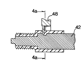
- Figure 4a is a cross-sectional view taken along
lines 4a-4a in Figure 4;
- Figure 4b is an enlarged view depicting the inter-
relation between the cores shown schematically in
! Figure 4; -~:
- Figure 5 is a cross-sectional view of a core
assembly for moulding a connector with two resilient
projections for joining two corrugated conduits together;
- Figure 6 is a schematical view of a core assembly ~ .
in accordance with a first variant;
~ - Figure 6a is a cross-sectional view taken along
¦ lines 6a-6a in Figure 6;
- Figure 6b is an enlarged view of the core aæsembly ~::
shown in Figure 6, depicting the camming action of the
inner core to raise the resilient tonque of the connector
'i from the recess on the inner core;
- Figure 7 is a schematical view of a core assembly
~i in ~ccordance with a second variant;
q 25 - Figure 7a is a cross-sectional view taken along
lines 7a-7a in Figure 7;
~.
i ~
1 330693
-- 10 --
- Figure 7b is a cross-sectional view taken along
lines 7b-7b in Figure 7; and
- Eigure 7c is a cross-sectional view of the
resilient tongue of the connector manufactured by the set-
up illustrated in Figure 7.
Throughout the drawings, analogous elements are
designated by the same reference numerals.
DESCRIPTIO~ OF PREF~RRED EHBODIHENTS
A conventional moulding assembly for producing
connectors for corrugated tubing is schematically depicted
in Figure 1. The moulding assembly 10 comprises mould
halves 12 and 14 moveable one with respect to the other
and meetlng along a parting line. A core assembly
comprlsing an inner core 16 and an outer core 18 defines
with the mould halves 12 and 14 a moulding cavity which is
filled with plastic material through an injection channel
20. The outer core 18 is fixed on the mould half 12 and
moves in unison therewith relatively to the inner core 16.
The assembly 10 also comprises an ejector assembly 19
for extracting the connector from the inner core 16 when
the moulding cycle is completed.
.
. .'- '
:... ..
. '
~s~
1 3306q3
The structure of the connector manufactured by the
moulding assembly lo is illustrated in greater detail in
Figures 2, 2a, 2b, 3 and 3a. The connector 22 has a
generally circular body defining a sleeve 23 for receiving
5an extremity of a section of corrugated tubing. A
resilient finger 24 carries a tongue 26 projecting
radially inwardly in the cavity of the sleeve 23. The
tongue 26 comprises an oblique cammming surface 28 facing
towards the tubing entry end of the sleeve 23 and an
10opposite vertical flat locking surface 30.
:
To form the tongue 26, a recess 32 is machined on the
inner core 16, comprising a slanted surface 34 forming the
camming surface 28 of the tongue 26, and a vertical face
1536 forming the locking surface 30. -~
¦ The outer core 18 which comes in contact with the
inner core 16 during the moulding cycle is used to free
the resilient finger 24 on its three sides. Although not
20illustrated in the drawings, it will be appreciated that
the outer core 18 has a U-shaped structure in cross-
section, including two parallel end flanges positioned at
a right angle with respect to an intermediate flange. The
intermediate flange and one of the end flanges are shown
25in Figure 3 and are designated by the numerals 38 and 40
respectively.
:;:
,
~ 1 330693
- 12 -
A major drawback of the moulding assembly 10 resides
in the interference created between the locking surface 30
of the tongue 26 and the conforming surface 36 in the
recess 32. If one tries to strip the solidified connector
from the inner core 16 using the ejector assembly 19, the
tongue 26 will likely be sheared off.
To address this problem, the invention provides an
improved core assembly illustrated in Figures 4 to 7c. A
preferred embodiment of the core assembly ls illustrated
in Figures 4, 4a and 4b, comprising an inner cylindrical
core 42 comprising a tongue forming recess 44 provided
with a camming surface 46, facing the slanted surface 34
and extending generally in a circumferential direction
with respect to the body of the core 42.
The outer core designated by the numeral 48 is also
modified by comparison to the outer core 18 previously
described. More particularly, the intermediate flange 50
of the outer core 48 comprises sidewalls 52 and 54 and a
slanted bottom wall 56 mating with the camming surface 46
in the recess 44 of the inner core 42.
During the moulding cycle, the position of the cores
48 and 42 is as shown in Figure 4~. It will be
appreciated that the outer core 48 partially blocks off
~, , ~, ~ . . . . :
~ :
.' - ' '' ' ' ' '
1 3306q3
- 13 -
the recess 44 in the inner core 42, acting as a barrier
element preventing the plastic material to flow in contact
with the camming surface 46. It will further be
appreciated that the cooperation of the cores 42 and 48
provides a tongue forming recess 44 which is identical in
shape to the recess 32 used in conjunction with the prior
art moulding assembly 10. Therefore, the arrangement
shown in Figures 4, 4a and 4b will produce a locking
tongue having a shape identical to the locking tongue 26
illustrated in Figure 2b.
When the moulding cycle is completed, the outer core
48 is moved away from the inner core 42. When the ejector
assembly pushes the solidified connector 22 out of the
inner core 42, the camming surface 46 will smoothly raise
the resilient tongue from the recess 44, allowing to free
the connector 22 without any damage thereto.
The same inventive concept may be applied for the
2Q construction of a mould to produce a connector with two
resilient tongues spaced apart along the centerline of the
connector, as illustrated in Figure 5. Such an
arrangement comprises two cores 42 moveable toward and
away from each other along the common centerllne 58, each
core 42 being associated with an outer core 48 received
into a respective tongue forming recess 44. The operation
: ~
~ . :
1 330693
- 14 -
of the inner and the outer cores 48 and 42 is identical to
the previously described embodiment.
A variant of the core assembly according to the
S invention ls illustra~ed in Figures 6, 6a and 6b. The
inner core designated by the reference 60 is provided with
a tongue forming recess 61 comprising the oblique surface
34 and a camming surface 62 generally transversal to the
oblique surface 34. Contrary to the previously described
embodiment, the camming surface 62 is not shielded durlng
the mould filling stage, therefore it will produce an
impression on the locking tongue 66. The impression is in
the form of a slant designated by the numeral 64.
In order to cam the resilient tongue 66 out of the
recess 61, the inner core 60 must be rotated in a
clockwise direction as shown by the arrow 68. When the
inner core 60 has reached a predetermined angular position
and the tongue 66 has been raised from the core 60, as
shown in Figure 6b, a standard ejector assembly may be
used to slide the solidified connector off the inner core
' 60.
This embodiment allows to produce a connector with a
locking tongue slightly narrower by comparison to the
previous embodiment, yet effective for holding onto the
,~, . . ~
1 33n~93
- 15 -
corrugated tubing. However, the mould construction,
because of the rotation of the inner core 60 is
complicated, especially on multi-cavity moulds. This
raises the original cost of the mould and also increases
the mould maintenance costs.
A further variant of the invention is illustrated in
Figures 7, 7a, 7b and 7c.
The cylindrical inner core 70 is provided with a
tongue forming recess 72 in which is machined a narrow
camming face 74 extending in a generally circumferential
direction with respect to the body of the inner core 70.
At the level of the camming face 74, the recess 72 is V-
shaped in cross-section.
An outer core 76 used to free the resilient tongue on
three sides enters the recess 72. The outer core 76 is
provided with a notch 78 to clear the camming surface 74.
Thiæ arrangement produces a locking tongue 80
provided with a narrow camming face 82 on the locking face
84 of the tongue 80.
At the end of the moulding cycle, once the mass of
plastic material has solidified, the mould is opened and
`
.
1 330693
- 16 -
the outer core 76 is removed. At that time, a standard
ejector is able to strip the connector off the inner core
because, while the connector moves forward, the
cooperating cam faces 74 and 82 in the recess 72 and on
the tongue 80 respectively, raise the tongue out of the
recess 72. This method if effective, however, it reduces
the width of the locking surface of the tongue, therefore
making it the least effective in holding onto the
corrugated tubing among all embodiments described herein.
It should be understood that the above description of
preferred embodiments of the lnvention should not be
interpreted in any limiting manner since they may be
refined in various ways without departing from the ~pirit
of the invention. The scope of the invention is defined
in the annexed claims.
.
.~ .
'''' ' ':
~, ' . . .