Note: Descriptions are shown in the official language in which they were submitted.
~3~7~
-- 1 --
FIELD OF THE INVENTION
This invention relates to tamper evident
plastic caps for indicating the condition of containers
and particularly to caps having separable or breakaway
portions to provide a clear and unequivocal indicator of
the condition of the containers, e.g., that they have
been opened or tampered with. The invention also
relates to the method of forming the caps.
,
BACKGROUND OF THE INVENTION
~ -:
While bottle caps evidencing tampering by -~
means of depending breakaway rings and separable
portions are in popular current use, they have many
defects and limitations in their manufacture and
performance.
Malleable metals such as aluminum have been
used to produce breakaway ring caps wherein the lower
portion of the skirt contains a peripheral line of
weakness having spaced bridges and a ring portion
therebelow rolled inwardly onto and under a peripheral
locking ring on the bottle neck during capping to engage
it in an interference fit. When the container is
uncapped, the bridges break, leaving the depending ring
attached to the bottle neck. An option to such a cap
design ls the addition of vertical lines of weakness
peripherally spaced, wherein the depending ring ruptures
and the ring portions so produced remain affixed to the
cap upon its removal Erom the container. ~ common
defect in the performance of such a cap is that it is
entirely dependent on the control maintained in the
cap-rolling operation and since this is accomplished on
,~ the packaging line it is often poorly controlled with
- 35 the result that such caps can appear untampered with in
' :'
,.~
~': .::
133~779
cases where they have been. Additional defects and
limitations on the use of metal roll-on caps result from
sometimes poorly formed and easily stripped threads;
high frictional resistance with the bottle neck,
especially with those of glass, making both capping and
resealing dlfficult and erratic; frequent loss of seal
when the caps are dented, especially noted in pressurized
containers; diEficulty in uncapping due to poorly
defined ext~rior fluting needed to adequately grip the ' '
cap; and their rapidly rising cost. Some oE these
limitations can be reduced or eliminated by preforming
the entire cap prior to capping including a peripheral
line of weakness and a ring with an interfering bead ~'
therebelow. However, the non-resilient nature of such
caps call for special container neck designs and cap
skirt designs with their own set of limitations and -
deects as well as restrictions on the type of container
materials which are suitable to coact with tihem. See, '
for example, Leftault, U.S. Patent No. 3,460,703.
As a result of the defects and limitations ;~
noted for metal tamper evident caps, a substantial ~
lnterest has been displayed in the use of plastic caps ~ -
for such purposes. Plastics caps present prospects for
easier uncapping and more reliable resealing, resistance
to denting and resultant loss of seal, well defined
exterior fluting for good gripping and comparatively
lower cost. However,'plastic caps introduce a d'ifferen't
set of limitations encountered in their manufacture, ''~ '
capping and subsequent performance. Early tamper ~ ~
30 evident plastic caps possessed depending rings which ~'
could be heat-shrunk to engage the bottle neck locking
ring. However, this approach imposed on the packager
~ the added bottling line operation and expense of heating
i; and shrinking the ring after capping. In addition, '
difficulty in precisely controlling the operation also
~,j
~ii ~ ~.
.~' ,. .~.
.,i : ~
.. 1 ':
- ~33Q~79
has led to erratic shrinkage with the result that caps
appeared tampered with when they had not been.
As a result of objections to the heat shrunk
tamper evident plastic cap, interest has turned to
producing the required ring undercut for an interference
fit with the neck prior to the capping operation. To
j date this goal has been achieved only by making
¦ undesirable compromises in manufacturing complexity and
cost to achieve the undercut as well as by loss of some
effectiveness in performing the tamper evidence function
~ as a result of the ring design and the inherent nature
1i and properties of plastic materials. Ring undercuts
j which are solid, molded-in circumferential beads
preclude the use of the more rigid, "non strippable"
polymers such as polystyrene and add to manufacturing
complexity and cost by requiring molds with complicated
part ejection systems which increase mold cost and lower
molding productivity. A slitting operation subsequent
to molding to provide the line of weakness may also be
required. However, its tamper evidence may be marginal
because the amount of undercut possible even with such
compromises typically is also marginal. That is, the
feature may grip the bottle neck sufficiently to perform ~-~
adequately in normal use but not when confronted by a
serious tamperer. The performance of such features is
also impaired by the inherent ease of deformation and
elongation of the plastic materials used which may allow
them to stretch beyond their elastic limit during
capping, increasing their diameter and thereby reducing
~ 30 the amount of ring interference with the container neck. `
!~, Further, such breakaway rings are sometimes engaged with
the container neck under a continuing stress which
over a period of time produces plastic creep, thereby
;l further reducing the tenacity of the gripping engagement ;~
~` ¦~ 35 and the integrity of the tamper evidence. -
~:
~:~. ` ',; ~
~i'
'~,
~ 133
Attempts to avoid the problems associated with
producing plastic caps having a solid molded-in undercut
on its breakaway ring have led to designs and manufactuing
methods which produce a plurality of flaps on the ring
in~erior which may fold out of the way on removal from
the mold and which are subsequently folded into an
interfering position prior to capping. See, for
example, Wilde et al, U.S. Patent No. 4,497,765,
Grussen, U.S. Patent No. 4,394,918 and Ostrowsky, U.S.
Patent No. 4,470,513. Such approaches have their own
manufacturing problems which include complex and costly
molds, manufacturing operations subsequent to molding or
I because of the ready foldability of their interference-
¦ producing flaps, their tamper evidence can be readily
¦ 15 Eoiled by a serious tamperer.
Another problem is associated with the fact
that otherwise standard bottle neck designs often vary
only because their locking ring dimensions vary and
prior art plastic caps having preformed breakaway rings ~;
are specific to a single bottle neck design. As a
result a cap from a given production mold can only be j~
used by packagers employing very much the same bottle
neck locking ring design and dimensions. This dictates
the use of a larger number of smaller molds resulting in
reduced productivity and higher cap manufacturing cost.
Also, it has not generally been feasible to
produce metal or plastic~caps including depending rings
which break into segments and which remain attached to
, the cap, except by using roll-on metal or heat shrink
plastic ringsz with the various deficiencies already
noted. Plastic caps with molded-in ring undercuts and -
vertical lines of weakness present problems with
¦ premature ring breakage during mold removal or during
~ capping.
;~ 35 Thus, known tamper evident caps with depending
,~
~.'
.,. ..
~, :`
1330779
~ - 5 -
J breakaway ring features are beset with drawbacks and problems
j associated with the inherent characteristics of the materials
¦ selected; the need to perform dif~ficult-to-control operations on
packaging lines; complex and expensive manufacturing tools; low
manufacturing productivity and high costs; the fact that the more
rigid plastics are restricted in use; and the relative ease with
which the feature may be overcome by a serious tamperer and other
problems.
`.1 ,UMMARY OF' THE INVENTION
lo In a broad aspect, the present invention relates to a method
of forming a tamper evident cap for a container, comprising:
moulding a cap from plastic having a skirt including a lower free
end, providing a line of weakness in said skirt, and engaging
said lower free end of the plastic skirt with an essentially -
concave surface of a curling tool to curve said end into a curled
resilient interfering free end which reduces the internal breadth ~ .
o~' said skirt prior to capping and which is adapted upon capping :
to provide an interference with a container so that upon initial
removal of the aap the line of weakness separates to thereby ~.`
. 20 indicate the condition of the container.
~,
'1 In another broad aspect, the present invention relates to a
~ method of forming a tàmper evident cap for a container,
i comprising: moulding a cap from plastic having a skirt including :
,1
a lower free end with a rim, providing a line oE weakness in said
plastic skirt, and engaging said lower free end of said plastic
~, .,
~ , ,,
1 3307~9
~~ -5a-
skirt with an essentially concave surface of a curling tool to
progressively curl said rim as said free end moves along said
essentially concave surface of the curling tool inwardly and
upwardly into a curled resilient interfering free end which
reduces the internal breadth of said plastic skirt prior to
capping and which is adapted upon capping to provide an
interference with a container so that upon initial removal of the
cap the line of weakness separates to indicate the condition of
the container.
In another broad aspect, the present invention relates to a
method of forming a tamper evident cap for a container,
comprising: moulding a cap from plastic having a skirt including
. a lower free end with a rim, providing a line of weakness in said
skirt, and engaging said lower rim of said skirt in axial
compression with an essentially concave surface of a curling tool
to progressively curl said rim as said free end moves along said .
essentially conaave surface of the curling tool inwardly from
said skirt, upwardly and outwardly from said concave surface
! wherein said rim and adjacent free end continue to curl in ~:
response to the stresses developed therein while in contact with
¦ said essentially concave surface to produce a resilient free end
having a cross sectional shape of an "0" which reduces the
internal breà~th of saidi plastic skirt prior to~capping and which
is adapted upon capping to provide an interference with a
container so that Upon initial removal of the cap the line of
weakness separates to indicate the condition of the container.
.'.'1 , .
':il `.
.
,1 .~
.
.. -5b-
- 1330779
In another broad aspect, the present invention relates to a
method of forming a tamper evident cap for a container,
comprising: moulding a cap from plastic having a skirt including
a lower free end with a rim; providing a line of weakness in said
skirt, and engaging said lower rim of said skirt with an
essentially concave surface of a curling tool to progressively
curl said rim as said free end moves along said essentially
concave surface of the curling tool inwardly from said skirt,
upwardly and outwardly from said concave surface wherein said rim
and adjacent free end continue to curl in response to the
stresses developed therein while in contact with said essentially -~
concave surface to produce a resilient free end having a cross-
sectional shape of a coiled ring which reduces the internal
¦ breadth of said plastic skirt prior to capping and which is ~ .
adapted upon capping to provide an interference with a container
so that upon initial removal of the cap the line of weakness
separates to indicate the condition of the container. ...
In another broad aspect, the present invention relates to a
tamper evident cap for a container, comprising: a top wall, and
a plastic skirt depending from said top wall including a line of
weakness therein, and a lower resilient free end which is curved
away from said skirt into a resilient curled free end of plastic
forming an arc of at leqst 50 degrees which is prestressed for
enhancing the engaging and interfering functions of said curled
free end, and wherein said prestressed curled free end reduces
the breadth of said skirt prior to capping and which is adapted
~
' ':
,~
,~ : ~
~J' ~ . ,
~
i- -5c- ~33~79
upon capping to provide an interference with a container so that
upon initial removal of the cap from the container the line of
weakness separates to indicate the condition of the container.
In a further broad aspect, the present invention relates to
a tamper evident cap for a container, comprising: a top wall, and
a plastic skirt depending from said top wall including a line of
weakness therein, and a lower resilient free end with a rim
wherein said free end is curled away from said skirt into a cross
sectional shape selected from the group consisting of a coil or O
¦ 10 which reduces the internal breadth of said skirt prior to capping
1 and which is adapted upon capping to provide interference with a
container so that upon initial removal of the cap from the
container the line of weakness separates to indicate the
condition of the container.
In yet a further broad aspect, the present invention relates
to a tamper evident cap for a container, comprising:
~ a top wall, and a plastic skirt depending from said top wall
¦ having a line of weakness therein, and a lower resilient free end
! terminating in a rim wherein said free end i5 curled inwardly
away from said skirt into a stressed cross sectional shape
selected from the group consisting of a coil or O which reduces
the internal breadth of said skirt prior to capping and which is
, adapted upon capping to provide an interference with a container
¦ so that upon initial removal of the cap the line of weakness ~;
separates to indica~e the condition of the container.
,"
,;.1
~ ~ Z
:, ,.'
:, .
:'
' !~ i, ~ ."
~-- ~L330779
-5d-
In accordance with the present invention, there is provided
a new and unique tamper evident cap for a container having a
lower breakaway or separable ring portion and a method for
producing such ring portions, wherein the cap has a simplified
design; low mould and production cost; readily controlled and
uniform quality and performance; a wide selection of plastics
which are suitable; an ability to coact with a greater variety
of container neck designs and dimensions; tamper evidence which
is difficult-to-defeat and imposed stresses which reinforce the
function of the cap.
Generally, the cap of the invention is used with containers
having an opening surrounded by a lip or rim with a depending
~ neck having an upper means for releasably engaging a cap and a
., lower means for interfering with a ring portion of the cap so
that the ring, upon uncapping, either will break from the cap or
separate into segments while remaining attached to the cap.
: ~he cap of the invention includes a lid for closing and
opening the container, a depending skirt having means for
. relea~ably engaging the container engaging means in closing and
; 20 openlng the container, a . - -
l ~ ~:
,.,, ' / ~ ~
`! ~
' ~ / '
~., ~
:` ~ . / '.
! ~ ~
,~ '.
`~.
i`~'', ~.
33~9
plastic ring depending from the skirt having a curled
portion at its lower end providing a reduced internal
dimension which engages the underside of the container
I interfering means and which has induced stresses therein
¦ 5 that enhance and reinforce its engaging functions. In
~ addition, lines of weakness in the ring are included
¦~ either as an intermediate peripheral line of weakness
between the skirt and curled portion or vertical lines
~ of weakness in the curled portion or both.
3 10 In capping, the curled portion is sufficiently
¦ resilient to pass about and below the container inter-
fering means and into interfering engagement therewith
without apparent rupturing of the described lines of
weaknesses. In the initial uncapping, either the
peripheral line of weakness will rupture leaving the
ring on the container or the vertical lines of weakness
, will rupture and separate the ring into segments while
allowing the entire cap to be removed. In either -~
embodiment clear evidence of tampering or opening is
prcvided.
In a preferred embodiment, the cap is molded
and, as molded, includes a generally cylindrical tube or
band depending from the cap skirt which is reformed by
tools of the invention that define the lower and inner
and/or outer portions of the curled ring portion into
the desired curvilinear cross sectional shapes, such as
an O, U, J or co~il. Typically, the desired cross
sectional shapes of the invention can provide reduced ~ --
internal dimensions for a polypropylene band of at least
30 about 5 per cent for a 28 mm cap and an arc or curved ~ ~`
portion of at least about 50 degrees.
In a preferred embodiment, the cylindrical
band is reformed by curling into a hollow "0" ring shape
wherein its outside diameter is typically close to that
of its original outside diameter and its inside diameter
: ~
,
:.,
~ !~ ¦ ~ ~
^
~33~
_ 7 _ ~
O
is substantially less than the outside diameter of the
engaging portion of the container neck. The reforming
is achieved by means of a curling tool which compresses
~ the lip of the cylindrical tube preform thereby turning
¦ 5 it inwardly and then upwardly channeling and gradually
altering the direction of such movement over its curved
¦ working surfaces. The initiation of the curling action
¦ may be facilitated by providing a taper to the lower
free end of the preform. Such a curling action at this
point produces a "J" shape or semi-circular radial cross
¦ section. After leaving the curved working surface of
the tool as it further compresses the cylindrical
preform, the lip takes an upward and outward direction
resulting from the continuing compression and the
stresses imposed by its plastic memory, thereby
completing the formation of the hollow "0" ring shape.
In another embodiment, the compression of the
cylindrical portion can proceed beyond this point and
; produce a coiled ring.
To facilitate the curling operation or to ~ ~
alter the dimensions, shape or character of the ~ ~;
resultant curled ring, the curling tool can be heated,
spun or rolled along the free end of the cylindrical
portion during its shaping. The periphery of the free
; ~ 25 end of the cylindrical portion may be curled simul-
taneously or sequentiallyO In other embodiments, the
ring can be exposed to elevated temperatures for shor`t
periods before cappiny to alter its dimensions, shape or
character or the preform for the ring can be heat
30 treated for the same purpose. ~;
A feature of the invention is that the use of
the curling action to reform the cap ring lowec end
portion not only produces the desired 190" ring or other ~ `~
; shape with reduced internal diameter, but also alters
3S and improves the inherent properties of the plastic
;~,. . .
,~. : j,.
i.~,;
..
.'' `'.'''.. '''''`'";''"','::' ~ ' ` :
133~
thereat to reinforce its neck engaging strength. That
is, the curling operation during its deformation and
reforming of the plastic in the lower end portion also
produces built-in stresses therein which are distributed
in such a way as to enhance its function. This
prestressing places the outward portion of the "0" ring
shape in a state of tension or extension and the inward,
neck engaging portion in a balancing state of compression.
Such a condition of compression increases the effective
elastic limit and tensile strength of the plastic so
that the ring will better resist temporary or permanent
elongation and loss of interference with its coacting
neck interference means.
I Thus, it is significant to note that the
curling method of the invention used to produce the cap
ring portion on the one hand produces the desired shape
and interfering means by exceeding the elastic and
tensile limits of the plastic, yet, on the other hand,
yields an article having greatly enhanced elastic and
tensile limits in the portion of the ring which performs
the critical neck engaging function.
Another feature of the invention is that the
cap, as molded, has no interfering bead or other shape
projecting from the interior of its cylindrical tube ;
preform as in prior art cap designs which can interfere
with ejection of the cap from its production mold. As a
result, simple andllow cost mold ejection mechanisms can
be used. ;
; For instance when made from such semi-rigid
plastics as polypropylene and polyethylene, the entire
cap can be stripped from the mold, avoiding otherwise
called for mold parts and operations such as unscrewing,
side-acting or other mechanisms and permitting a closer
spacing of the mold cavities. This lowers manufacturing
35 cost through lower cost and longer lasting molds and ~
,,, : -"
.~~ ~ .
~'
~ ~ R~
;,,~ ~". '":. " "` ` ' : "' " ''`"''' """'`''" """'''','':"' '"" " ''.'' ' "'' ''' '"'' " ., ', `' :
1330~
o
higher production rates derived from producing larger
numbers of caps per molding cycle and reductions in the
length of the molding cycle.
Another feature of the invention derived from
the fact that the cylindrical tube portion of the cap,
as molded~ has no undercut to interfere with mold
ejection, is that rigid plastics with low elongation
characteristics such as polystyrene can be used with the
only additional requirement being that suitable ejection
means be used for other cap undercuts such as internal
threads. Such requirements are readily met by forming
the threads using unscrewing or collapsing core molds
thereby allowing the cap manufacturer to avail itself of
the potential merits of employing such rigid plastics to
achieve lower manufacturing cost or improved cap
performance. While such rigid plastics lack large
amounts of elongation, they do possess a suffiaient ;`
amount to be suitably curled for the successful practice ~ `
of the invention. This results in large part from the
imposition of significant stresses by the curling method
oE the invention which enhance the plastics properties
` by compressing the interior, working portion of the
curled breakaway ring effectively increasing its ;~
elongation and strength thereat. ~ ;~
Still another feature of the cap of the
invention derived from producing the ring undercut -
subsequent to molding is that the degree of undercut and
interference with the bottle neck is not related to or
limited to the degree of difficulty in removing such `
undercuts from the mold. As a result, very much deeper
, ~ undercuts can be made to achieve a greater gripping
;i~ tenacity with the bottle neck, thereby presenting would
be tamperers with a higher degree of difficulty in
defeating the tamper evidence and assuring a more
35 reliable performance in normal use. ~-~
! I` ~
~',' :,
~ ~,:`"~'''',','`,:~' ,''.''"''''
1330779
--10--
Yet another feature of the invention is that relative height
and diameter of the curled interfering portion of the ring is
determined ln a separate reforming operation so that a single cap
as moulded, may be used to produce caps which will fit a variety
of bottle neck designs where the height and diameter of the neck
locking ring varies. The costs of the curling tools and the
curling operation affect overall cap costs very little, enabling
the cap manufacturer to take advantage of the economies of larger
scale production for a number of customers or users from fewer
and larger production molds.
Another feature of the invention is that the curling
operation of the invention may be performed in siequence with or
as a part of other steps taken in the manufacture of the cap.
That is, it may be performed during or consequent to removal from
production molds or during or consequent to cap finishing
operations such as liner insertion or lid decoration. It may
¦ also be performed simultaneously with or consequent to a curling
operation to produce the linerless seal described in U.S. Patent ~
No. 4,708,255, lssued November 24, 1987 from Application U.S. ;
Serial No. 809,058i, filed December 12, 1985 by Mortimer Stafford
~hompson, and which patent is assigned to Tri-Tech Systems
International, Inc. the assignee of the present application.
Also the curling operation has been demonstrated to be non-
critical in respect to unusual control or conditions so that
¦ automatic operation to produce uniform product can be readily
l used to achieve high quality at low cost.
Another feature of the invention derived from producing the
undercut of the ring sublse~uent to moulding is that the
peripheral or vertical lines of weakness can be readily moulded `~
into the cap, thus avoiding subsequent slitting operations.
Since the cylindrical tube preform
I` ,
'l ....
! :
..1~`
¦ ` ~; .h ':
`:1
~:
r~
~307~9
has no internal bead to resist stripping from the mold
and since the tube itself is relatively thin so that it
presents little resistance to beiny stripped, the
bridges which attach it to the upper portion of the cap
can be strong enough so that they do not break when
being stripped from the mold and yet weak enough to
readily break in use during removal of the cap from its
bottle neck. For the same reasons the vertical lines of
weakness can be ~eadily molded into the tube preform
without concern for premature breakage upon mold
removal. Thus, the cap of the invention may be molded
with the same ease and freedom from limitations as
currently produced caps haviny heat shrink bands as
their tamper evidence.
Another feature derived from the fact that the
line of weakness can be readily produced in the mold is
that its presence, indicated by the distinctive molded
slots and bridges, can be made quite obvious, calling
the consumer's attention to the tamper evident feature
20 prior to purchase.
'rhus, the caps of the invention have simple
design; are less easily tampered with and are more
reliable; have improved versatility and broader
usefulne5s; can use more rigid plastics; have enhanced
; 25 physical properties due to prestressing; and are low
cost.
'rhe process of!the invention can perfo!rm
.~
automatically and reliably without unusual controls or
~ conditions. It is composed of simple operations ;~
t 30 yielding low cost caps based on lower cost and longer
~ lasting molds and tools; shorter molding cycles; greater
f density of and numbers of cavities per mold; the
:!. production of the lines of weakness in the production
mold, and greater economy of scale derived from the
~t 35 versatility of use for the output of a single mold.
:-! :. :- :
j!
: : , ,
5,!
f`~ ~f ~
L33~7r~
_ 12_
BRIEF DESCRIPTION OF THE DRAWINGS
FIGURE 1 is a bottom perspective view of one
embodiment of the cap of the invention, partially broken
5 away to show details thereof; -
FIGURE 2 is a bottom perspective view of the
cap of FIGURE l after molding and which, at this stage,
I includes a lower preform portion for the ring;
¦ FIGURE 3 is a longitudinal sectional view of
the cap of FIGURE 2, wherein the preform is about to be
engaged by a curling tool of the invention; :-
FIGURE 4 generally is the same as FIGURE 3,
except that the curling tool has engaged the preorm
and initiated the inward curling of the free end
thereof;
. FIGURE 5 is generally the same as FIGURE 4,
except the curling tool has almost completed the curling
of the ring;
FIGURE 6 is a longitudinal sectional view of
. 20 the cap of FIGURE l with a completed "O" ring ready for ~,:
: engaging the neck finish of a bottle;
FIGURE 7 is the same as FIGURE 6, except that
. the bottle has been closed by the cap and the "O" ring
is in engagement with the interfering means on the neck
25 finish; `~
FIGURE 8 is a longitudinal view of the cap and : :
. neck finish of FIGURE 7, wherein the cap has been
. removed from the neck finish leaving the ring portion
thereon as evidence of opening or tampering with the
i 30 container; -
i; FIGURE 9 is an enlarged sectional view of the
ring portion of the cap shown in FIGURES l and 6, :~
: schematically illustrating the stresses induced therein ~ :
: : in the hoop direction; ~:
., 35 FIGURE 10 is a plan view of the ring portion ;~
. ~
~;` ~ :
,,,~ ; ~
,~
of FIGURE 9;
FIGURE 11 is a stress-strain graph for the
stresses in the previously illustrated ring portion;
FIGURE 12 schematically illustrates what
occurs to the "O" ring of FIGURE 11 upon release of the
hoop stresses;
FIGURE 13 is a longitudinal sectional view
of another embodiment of the cap of the invention
including a preform for the ring and a linerless seal
within the cap ready for engagement by a curling tool of
the invention;
FIGURE 14 is the same as FIGURE 13, except
that the curling tool has fully engaged the preform
portions of the cap to form a linerless seal having an
O-shape cross sectional shape and an inwardly curled
ring having a J-shape cross sectional configuration; :
FIGURE 15 is a longitudinal sectional view of ::
the completely formed cap of FIGURE 14 engaging,
initially closing and sealing the illustrated bottle;
. ~ FIGURE 16 is a longitudinal sectional view of
another embodiment of a cap of the invention after ` `~
molding and before the preformed lower end is curled to ~:~
form a ring;
. FIG~RE 17 is a longitudinal sectional view of -
25 the cap of FIGURE 16, wherein the preform has been :~
curled outwardly to form a ring having a coiled cross ~ .
; sectional shape;~
i FIGURE 18 is a longitudinal sectional view of
the completed cap of FIGURE 17 engaging and initially
closing the illustrated bottle;
FIGURE 19 is a longitudinal sectional view of
still another embodiment of a cap of the invention,
't~ wherein the preform portion has a larger diameter than
, the diameter of the skirt portion of the cap and is
- 35 about to be engaged by a holder and curling tool of the ~.
'`t' " '
i,. ., ~:, !
i;!
133~7~ ~
-14 -
o
invention to form an inwardly curled ring in the
preform;
FIG~RE 20 i5 the same as FIGURE 19 except that
the inwardly curled ring has been fully formed;
FIGURE 21 is a longitudinal sectional view of
the finished cap of FIGURE 20 fully engaging and closing ~:
the illustrated bottle;
FIGURE 22 is a longitudinal sectional view of
another embodiment of a cap of the invention after ~ ~
10 molding, wherein the preform includes vertical slits and : .,.
I notches in its free end;
I FIGURE 23 is the same as FIGURE 22, except
that an inward curled "O" ring has been formed in the :~
preform; ;
FIGURE 24 is a longitudinal sectional view of - "
the cap of FIGURE 23 engaging and initially closing the
illustrated bottle with the assistance of a capper;
FIGURE 25 is a longitudinal view of the cap of
: FIGURES 23 and 24 after the initial uncapping illustrating :~ :
.
20 the ruptured radial portions in the "O" ring while the ,'.:
; ring remains attached to the skirt of the cap; and '~:
, FIGURE 26 is a bottom view of the cap of
`. FIGURE 25.
; :
DE~AILED DESCRIPTION ~:
.
": . Referring to,iFigure 1 there is shown a; semir
,: rigid threaded cap 10 of plastic having a lid 12, a :;:
: depending peripheral internally threaded skirt 14;~
, 30 including an upper portion 13, an intermediate
peripheral line of weakness 17 and a lower breakaway
ring 16. The illustrated breakaway ring 16 includes a
cylindrical upper end 20 and a free curled lower end 24.
As shown, the end 24 of the breakaway ring 16 is curled
inwardly and forms a hollow annular "O" or coil ring.
~.` , - ',
", '1,~ ,
~.'
~ ~ 6, `~ ' '
133~77~
-15 -
o
The intermediate peripheral line of weakness 17 includes
a plurality of bridges 23 connecting the upper skirt
portion 13 with the upper end 20 of breakaway ring 16
and slots 25 between and separating the bridges 23.
Figure 2 shows the cap 10 of Figure 1, as
molded and before formation of ring 16, having a
tubular vertical band 18 with a lower free end 22 having
a lip 30 and an upper end 20 having spaced bumpers 19
which are integral with and which extend into the
bridges 23.
I Referring to Figures 3-5, there is shown a
preferred method of forming the curled portion 24 of .:.. ;
ring 16. As shown in Figure 3, the cap 10 is held in :~
holder 62 and already has been formed by conventional
molding techniques, such as injection molding, with the
vertical tubular band 18 having its upper end 20
integral with the bridges 23 and with its lower free end
22 ready for curling.
The curled portion 24 of ring 16 is formed
20 with a curling tool 26, which in Figure 3 has been ;~
positioned under the cap 10 ready to engage the lip 30
of the preformed band 18. The curling tool 26 includes
. an annular groove 28 of a concave cross section suitable
for shaplng and dimensioning the curled "O" ring portion
; 25 24.
As shown in Figure 4, the forming operation is
accomplished by pressing ! the groove 28 of the tool 26 '
against the lip 30 of the band 18. In this embodiment :
. the deepest portion 33 of groove 28 representing the ~.:
30 center of its concavity is located inwardly of the :~
cylindrical plane of band 18. This is shown by the
dotted lines 35 of Figure 3. Also, the groove 28 has a
slanted portion 39 outwardly and tangent to its ~`
concavity to facilitate centering of the tool and cap.
~; 35 At the initial engagement of lip 30 with groove 28 : .
-
~ 3307~
-16 -
the bridges 23 collapse and the tubular band 18 rotates
slightly in response. This response is assured by
dimensioning the bridges to be larger (and stronger) in
the radial direction and smaller (and weaker) in the
circumferential direction. When the bridges 23
collapse, upper end 20 of cylindrical band 18 presses
against the upper face 27 of slots 25 and is restrained
from further movement by the projecting restraining
means 21 located on the inner edge of the upper face 27
of slots 25 and by the upper face 27 itself. As the
movement of tool 26 relative to the wall 18 continues
the cylindrical sides of the wall 18, beginning with the
lip 30, are Eorced inwardly and upwardly to assume an
interim "J" shape 29. As this relative movement
continues the lip 30 is forced upwardly out of groove
28, and at the same time is forced outwardly in response
to the stresses developed therein while being shaped by
tool 26, thereby producing the desired "O" ring curl 24.
After formation of the curl 24, the curling tool 26 is
withdrawn from the cap 10 and the cap 10 is ready for
capping. As shown in Figure 3 there is a taper in lower
free end 22 extending from the rim 30 which facilitates
the initiation of the curl 24 and assures development of
a full round curve thereat.
Also to facilitate the curling operation of
the invention, in the case of polypropylene the tool 26
may be heated to~a,temperature of :L00F to 300F for ! '
curling cycles of one to five seconds. Lower temperatures
and cycles are preferred to maximize the desired
stresses of the invention imposed by the curling
operation on the curl 24 and discussed hereafter in ~ `~
Figures 9 to 13.
Typical dimensions of the "O" ring curl 24 in
a 28 mm polypropylene cap are about 0.050 to 0.120
inches for the curl height or width and about 0.015 to
~ ~ '
.~ b~
: '
'.:
-17 -
1~30779
0.040 inches in wall thickness with the radial cross
section curled about 270 to 540 degrees to reduce the
internal diameter of tubular wall 18 about 5 to 15
percent. --
Referring to Figures 6-8, there is illustrated
the use of the ring 16 of Figures 1-5 as a breakaway
tamper evident feature of the cap 10 for a bottle 36
(partially shown) having an externally threaded neck 38,
an upper thread 42 and a lower locking ring 40. As the
cap 10 is threaded onto the bottle neck 38, the curled
inside portion 32 of the ring 16, which is a smaller
dimension than locking ring 40, is stretched or
deflected and forced past the locking ring 40 into an
interfering engagement therewith as shown in Figure 7.
The ring 16 is restrained from upward movement by the
locking ring 40 so that the unthreading action will
rupture bridges 23 leaving the ring 16 on the bottle
neck 38 as evidence that the bottle has been previously
opened. This is illustrated by Figure 8. To maintain
20 the axial alignment between the ring 16 and the upper -;~
portion 13 of the skirt 14 during cap removal, spaced
bumpers 19 are located below each of -the bridges 23.
Without such bumpers 19, it is possible for the ring 16
to slide sideways under the locking ring 40 after some
o the bridges 23 have ruptured thereby compromising the
ability to rupture the remaining bridges 23 before ~
losing thread engagement. With the bumpers 19 engaging i ~;
the vertical surface 43 of locking ring 40, when one or
several, but not all, of the bridges 23 break, the ring ~-~
30 16 is held in axial alignment until all the bridges 23 ~
have ruptured. ~ ~-
The curling method of -the invention not only
produces the hollow "O" ring 24 or other shapes of the
invention creating the desired interference with the
bottle neck, but it also alters the inherent physical
~ !
. ! '
~330779
_ 18-
O
properties of the plastic in such a way as to enhance
its neck-engagement tenacity. That is, the plastic at
the inwardly directed interfering portion 32 is made ;
stronger, more resilient and creep resistant as a result
of the stresses imposed on the plastic during the
curling operation. This is explained by FIGURES 9 to
12.
The curling operation, by imposing an
alternative shape on the cylindrical vertical band 18,
1~ introduces stresses to the resultant shape of the ring
16. That portion of the ring 16 which is stretched is
in extension or a state of tension and that part which
is compressed is in a state of compression. The
stresses vary with the degree of stretching or
compression and, as in any static condition, the total
amount and direction of each kind of stress balance one
another. The stresses of primary concern are those
imposed in the hoop direction since it is in this ~;
direction that the inside portion 32 of the cap ring 16
must be stretched to overcome its interference with the
bottle locking ring 40.
The hoop stresses introduced by the method of
the invention result from the increase or decrease of
the hoop diameter of the cylindrical band 18 when it is
reformed into the "O" ring 24 or other shape ring 16 of
the invention. If it is considered that the band 18 is
composed of an ilntegrated stack of hoops, each of which
must be expanded radially (stretched) or compressed to
produce the reformed shape, then a condition of tension
or compression will be imposed on each of the hoops in
the resultant shape as shown in FIGURES 9 and 10
. ,.
(respectively a radial cross section and a horizontal
plan view of the "O" ring 24). The level of stress is
relative to the distance from the location of the
3S original cylindrical band 18 and tension is highest at
", ' ;
~.,.
,~, 3 3 ~ ~ r~
point B located in that portion of the "O" ring 24 which
is furthest from the inside interfering portion 32 and,
therefore, plays a secondary role in gripping locking
ring 40; stresses are nil at the intermediate location
of the original cylindrical preform 18; and compression
is highest at point A located in that portion of the "O"
ring 24 which plays the principal role in gripping the
locking ring 40, the undercut 32 itself.
FIGURE 11 shows a typical stress-strain curve
for a semi-rigid plastic (e.g., polypropylene) suitable
for the practice of the invention. The condition of the
hoop stress at points B and A are shown on the curve~at
typical locations for the practice of the invention (5% -
elongation and beyond and the corresponding level of
15 compression). ~ `~
From the location of point A in FIGURE 11 it
can be seen that the curling action alters the proper-
ties of the inwardly directed undercut portion 32 of the
"O" ring 24 significantly. Because this undercut 32 is
highly compressed, its elastic modulus is maximized and
the amount that it can be elongated before plastic or
permanent deformation occurs is significantly increased
~proportional to the ratio of AE to OE in FIGURE 11).
The former increases the amount of stress required to
25 obtain enough elongation to overcome the interference -~
between the undercut 32 and the locking ring 40 and the
latter prevents ,the undercut 32 from permanently ! '
stretching during or after capping thereby maintaining a
relatively greater level of its engagement strength.
These factors are highly beneficial towards maximizing
the ability of the undercut portion 32 of the "O" ring
24 to generate the maximum amount of engagement with the
locking ring 40 and to resist decay oE such engagement
over long time periods resulting from plastic creep.
Thus it can be seen that the distribution of stresses
.. ~.
,,,.. ~
. ~ !,.. ,. ,."~.,.,.. ",",,
~, ... , .` !-' , ' ' :
133~7~
_20 _
imposed by the curling operation of the invention
contributes to the enhanced performance of the "O" ring
shape 24 to provide the required interference with the
bottle neck.
That the stresses described in the above
analysis do in fact exist and are distributed in the
manner described is demonstrated by annealing tests to
observe the changes in shape which develop as such
stresses are relieved. For such tests 0.020 inch thick
cylindrical bands 18 of polypropylene were curled in the
manner of the invention to yield "O" ring shapes 24
having a ring outside diameter of 1.230 inches, inside
diameter of 1.030 and a curl outside diameter of 0.100
inches. The "O" ring 24 was then split radially to ;
facilitate the full release of imposed stresses and then
exposed to a temperature of about 300F., somewhat under
the plastic's melting point, for five minutes. Under
these conditions, the "O" rings 24 opened up in the hoop
direction to a radius of 2.5 inches, a four-fold
increase, demonstrating the presence of very high levels
of hoop stresses and hoop stress differentials. r~he
dramatic nature of this result, illustrated in Figure
12, substantiates the preceding analysis wherein the
contribution of the stresses imposed by the curling
operation alters and enhances the physical properties of
the plastic used to manufacture the cap 10 so as to
develop higher levels~oE interference between the "O" ~ I`
ring 24 and the bottle neck locking ring 40 and less
decay of such interference.
In addition to an "O" ring, the ring 16 can be
of different cross sectional shapes which have the
described desirable properties, including J, U and
coiled cross sectional shapes.
Also, the ring 16 and its lower end 24 can
have various circumferential configurations. For
' .'
~:
.
1330779
-21-
example, the cap 10 has moulded can include a castellated band 18
or free end 22 having circumferential segments with spaces
therebetween. Thereafter, the free end 22 comprising segments
can be curled as described herein to produce a segmented curled
lower end 24 with spaces therebetween. Alternatively, the
unmodified band 18 can be curled by a curling tool 26 in whieh
the groove 28 is modified to produce on curling an undulated or
scallop shape to the inside portion 32 of the curl 24. In use,
such caps 10 will function as described to provide a clear
indication of the condition of the capped container.
The caps of the present invention also can be used for a
wid~ variety of containers and for a wide variety of produets.
Typically, eap sizes range from about 20mm to 120mm and bottle ~-
and/or jar sizes range from about 2 ounee to 128 ounee eapaeity.
Larger eapacity containers such as drums or kegs are also
suitable for the practice of the invention as are smaller vials
and other containers.
Further, the caps of the present invention can include other
features including metal lids, seals, etc. Speeifieally, the
eaps of the present invention ean inelude the linerless seals
deseribed in U.S. Patent No. 4,708,255, mentioned hereinabove.
Figures 13 - 15 are illustrative of how the curling ~ -
operation of the invention ean be eombined with the curling ;~
operation deseribed in U.S. Patent No. 4,708,255 to concurrently
form the ring 16 of the present invention and a linerless seal 70
of the invention of my copending application.
. 'i~ ~' ' ;,
, j~ .,s ", ,
l ~
~33~79
22
As shown in Figure 13, the cap 10 is molded
with a line of weakness 17 and a depending tubular band
18 as well as with the preform 72 for an internal
in-tegral or linerless seal 70. The preform 72 includes
5 a cylindrical or annular vertical wall 74 having an :
upper end 76 integral with the lid 12 and a depending
free end 78.
In the illustrative embodiment, the curling
tool 26 has an upper portion 80 with an annular groove
1~ 82 for forming an inward curl in the free end 78 and an ; -
annular groove 28 for forming an inward curl in the free
end 22. As illustrated, the tool upper portion 80 is
positioned within the annular groove 28, extends :~
upwardly, and has a diameter which is less than the
diameter of the cap 10 so that it can extend thereinto
to form the linerless seal 70. ~-~
In Figure 13 the tool 26 is positioned below
and within the cap 10 ready to engage simultaneously the
outer and inner tubular walls 18 and 72. Figure 14
shows the curling tool 26 fully engaged with cap 10
having completed the formation of an "O" ring linerless :.
seal 70 and a breakaway ring 16. In this embodiment the
wall 18 is curled to a lesser extent than for the "0" :~
ring curl 24 oE Figures 1-8 by stopping the curling ;
~5 operation at the stage illustrated by Figure 4. This ~ :
results in a "J" shape curl 29 for the ring 16 which :~
engages.locking ring 40 of bottle neck 38 as shown by
Figure 15. At the same time the linerless "O" ring seal
70 is a plug seal wbich engages and seals against the ~:
30 wall 84 of the bottle opening 86 in the neck 38 thereof.
Typical dimensions of the "J" shape curl 29 in ~
a 28 mm polypropylene cap are about 0.015 to 0.050 in .:~.
wall thickness with a radial cross section curled about
50 to 180 degrees to reduce the internal diameter of the ~n:
35 tubular wall 18 by about 5 to 15 percent. Also, since
. . '~
., :: .'
~ ' '
:
r
L 3 3 `(~ 7 79
the end 30 of the J shape curl 29 coacts directly with
the bottle locking ring 40, any taper provided therein
is minimal and typically would extend for a distance of ; -
less than 0.050 inches from the end 30. The beneficial
5 stresses developed by the curling operation in the
plastic of the "J" shape cross section is less than
those developed for the "0" ring shape 24 bu-t still well
within the desired levels of compression and improved
locking performance of the curled inside portion 32 of
10 ring 16 with locking ring 40 of bottle neck 38.
Referring now to Figures 16-18, there is shown ~-~
another embodiment of the ring 16 of the invention,
wherein the lower end 22 of the tube 18 is curled in an
opposite direction to the "0" ring curl 24 of Figures
lS 1-8 to provide an outward curl. In addition, the line ~
of weakness 17 is produced after molding. ~ `
Figure 16 shows the cap 10 after molding and
after a subsequent slitting operation to produce the
line of weakness 17 wherein the upper end 20 of band 18
20 i9 slit by appropriate knives (not shown) completely
through its wall but not through the spaced internal
bumpers 19. This results in spaced internal bridges 23
connecting the band or tube 18 through the bumpers 19 to `~
the upper skirt portion 13. Below the cap 10 the
25 curling tool 26 is positioned with its forming grooves
28 ready to engage the lower end 22 of band 18 so as to
shape it outwardly andiupwardly. The outward direction
of the curl 24 is achieved by locating the center of `
concavity 33 of groove 28 outwardly of the cylindrical ~ ~
30 plane of wall 18 as illustrated by the dotted lines 35 ;
of Figure 16. In this embodiment, to develop the
maximum amount of undercut 32 to engage the neck locking
ring 40 the undercut 32 must be displaced inwardly from
the upper end 20 of band 18 as much as possible.
35 Therefore it is necessary to develop the maximum
. , ,~ .
... ..
:::
13~7~
- 24-
curvature to the undercut 32. This is accomplished by ~ -
locating the center of concavity 33 of groove 28 close
to the plane of wall 18 and by removing any restraints
to the free inward displacement of undercut 32 resulting
from the stresses imposed by the curling operation, by
providing ample free space in the inward slanted portion
39 of groove 28 as shown in Figure 17. Figure 18 shows
the engagement of undercut 32 of the cap 10 with the
locking ring 40 of bottle neck 38 which results from the
10 curling method of this embodiment of the invention. -
Figures 19-21 illustrate another means of ~-
forming the line of weakness 17 subsequent to molding
and during the curling operation of the invention. In
this case the cap 10 is molded to produce the tubular
vertical band 18 having an inside diameter larger than
the outside diameter of the upper skirt portion 13 and
attached to skirt portion 13 by means of a radially
extending flange 44. In spaced arrangement on the ~.
underside of flange 44 are a plurality of bridges 23
which also connect band 18 to skirt portion 13. The
holder 46 for cap 18 during the curling operation is
constructed with a peripheral cutting edge 48 located
around the edge of its well 50. ~ ~
During the curling operation the cap 10 is ~-
placed in the well 50 of the cap holder 46 and the
groove 28 of the tool 26 engages the lip 30 of the cap
band 18. As thq,tool 26,proceeds to curl ,the band 18,
pressure is applied to the upper surface of flange 44 by
the holder cutting edge 48 which proceeds to sever
flange 44 so that it no longer connects band 18 to the
upper skirt portion 13 but cutting edge 48 does not
proceed to sever the spaced bridges 23 located on the
underside of flange 44. In this manner the desired line
of weakness 17 is created. ~,
Figure 21 shows the cap of Figure 20 in
'
::
133~7~
- 25-
engagement with the neck 38 of bottle 36. In this
embodiment the neck 38 has a comparatively large
diameter locking ring 40 and adjacent lower neck portion
41 so that the cap ring 16 undergoes a comparatively
S large expansion to snap over locking ring 40 and is also :
maintained in a state of significant expansion
thereafter. However, because the curling operation has
developed a state of significant compression in the ~.
inside portion 32 of ring 16 such expansion does not: ;
produce a comparatively high tension or elongation
therein to weaken it as discussed in Figures 9-12.
Referring now to Figures 22 to 26, still
another embodiment of the invention is illustrated,
wherein the ring 16 remains attached to the upper skirt
portion 13 of cap 10 upon its removal from the bottle
neck 38 as a result of strengthening the peripheral line
of weakness 17 and providing one or more vertical lines .. ,.
of weakness 92 in the ring 16. Figure 22 shows the cap : .
10 as molded with crack initiating notches 89 leading
20 into vertical grooves 90 ending in slots 25 which ~`
provide vertical lines of weakness 92 in the cylindrical
band 18 from its bottom rim 30 to its upper end 20. `: :
Between the slots 25 are bridges 23 connecting the upper .;~
portion 20 of band 18 to the upper skirt portion 13. -
Figure 23 shows the result of employing the. :~.
curling operation of the invention on band 18 to produce:i
the ring 16 havinglan '!O'~ ring shape 24 in.which the
notches 89 and the now radial/vertical grooves 90
produce radial/vertical .lines of weakness 92 throughout ..
30 the full cross section of the ring 16. :i:~
Figure 24 shows -the cap 10 fully seated on the ~:
bottle neck 38 after capping wherein the inside portioni.:
32 of the ring 16 has stretched to snap over the neck -~--
locking ring 40 with the result that the cracks 93
initiated by the notches 89 have progressed toward the
'~
i . . i 1 ` ,! . , ' ' . . . , , . ' ~ .. ,, ~, .. . .
-26 -
o 1330779
bottom 37 of the ring 16 as a result of said stretching.
However, since the ring 16 is hollow and the outer ''
portion 34 is not contiguous with the inner portion 32
but is more remotely connected through the bottom
portion 37, and because the outer portion 34 is
restrained by the capper head 88, it is not subjected to
significant stretching during the capping operation and '-
crack 93 does not propogate beyond the bottom portion
37. Because the ring 16 is hollow the capper head 88
can be made to prevent the outer ring portion 34 from
stre~ching without restraining the inner ring portion 32
from stretching, as required, and snapping over the neck
locking ring 40 during capping. This provides assurance
that the radial crack propogation does not occur in the
15 outer portion 34 and that the ring 16 remains intact '~
during and after the capping operation as shown in
Figure 24.
During uncapping the bridges 23 are of
sufficient cross section and strength to resist rupture. '
As a result, the uncapping stresses developed in the
ring 16 concentrate at the remaining portions of the
radial/vertical grooves 90 in the lower and outer ring
portions 37 and 34 which thereupon rupture in a tearing
action allowing the entire cap 10 with the broken ring ''~
25 portions 95 to be removed intact from bottle neck 38. , '
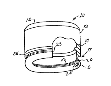
Figures 25 and 26 show the cap 10 after
uncappin,g wherein,las a result of the hoop,stresses
imposed on the ring 16 by the curling method of the
invention, the ends 94 of the broken ring portions 95 ~ '
30 spring outward,ly making the tamper evidence more obvious ;~
while at the same time facilitating the recapping of the
bottle by displacing the ring portions outwardly from
the cap lower opening 96. The degree to which the ',~
broken ring portions 95 and their ends 94 spring out-
35 wardly is governed by the lengths of slots 25 and the '~
13~7~ ~
_27 -
amount of hoop stress developed by the curling
operation.
The invention in its broader aspects is not
limited to the specific described embodiments and
S departures may be made therefrom within the scope of the
accompanying claims without departing from the
principles of the invention and without sacrificing its
chief advantages.
'
.~
, .,
~5 ;~ :
~ ~:
'''
: 35 ~ :
~.,