Note: Descriptions are shown in the official language in which they were submitted.
1 3 3 ~
FIELD OF_INVENTION
The present invention relates to a process and
a device which permits to establish a link between a manu-
facturing machine for envelopes having its own manual output
chain on the one hand and a totally different conditioning
machine on the other hand such as to permit the grouping of
the envelopes by lots as well as their transfer to the con-
ditioning machine in fully automatic manner including a
short circuit of the linkage device in cases of mal-functio-
ning with subsquent manual discharge of the output chain,
o such that the operation of the fabrication machine of the
envelopes is not interrupted.
The general term fabrication machine for envelo-
pes is used here for all types of machines which produce
elements of the type of envelopes for postal and non postal
containments~ bags andbellow type bags, disk jackets and
bags for food conditioning.
PRIOR ART
At the exit of the fabrication chain, the glued
and folded envelopes which are ready for utilisation are
stacked by means ofla distributor device, for example of
the rotating drum type having slots which are curved accor- ;~
ding to a snail-like path . Two driving belts assure
. - ,
-~ the displace~ent of the pile whereas a block which is mounted
-` 25 on the working table maintains this pile in vertical arran-
gement. The lots of envelopes are herewith manually punctured
whereby the block is approached towards the pile which is
thus the object of different conditionings.
~!IL
, ~ '
,
2. 133~ 360
OBJECT OF INVENTION
This working ~tation at the end of the chain is
relatively cumbersome and lt is desirable to automize this
operation. However, there ls an important pro~lem related to
this particulartech~que because the fabrication must not be
5 interrupted.The utilisation of a glue which dries rapidly
as well as the plurality of fabrication lines produces con-
siderable waste during the start up sf the machine which
should therefore occur as rare as posslble.
SUMMARY OF INVENTION
The present invention proposes therefore a pro-
cess and a device whichpermits,in spite of its high production
rate,to establish a link between a fabrication machine for
envelopes which proposes its own manual output chain with
temporary stock and a conditioning station, which link
5 assures thegrouping of the envelopes by lots and their transfer
towards the conditioning stations in totally automatic manner.
This link is particularly characterized in that the automatic
linkins device, in order to avoid interuption of the fabri-
cation machine, is short circuited in favour of the manual
discharge chain in case of an accident detected by sensors
20 on the linking device. Thus, the fabrication ls not interrupted
when the automatic linking device is installed. The linking
device, in order to carry out the present process, is consti-
tuted by a pivo~ing support plate for the means for orienta-
tion a~.d separa ion, a mobile bar ccnnected to a chain which
25 is driven by t~o pignons, one of which is freely mounted and
the other one being driven by a motor, a buffer-compensa-
tor for the envelopes, a counter for the envelopes, a rocking
finger which is controlled by said counter, a belt transporter,
a pivoting distributor with an associated conveyor of the
30 horizontal band type with catch studs.
BRIEF DESCRIPTION OF THE DRAWINGS
.
Figure 1 is a sectional view of the orientation
device accordinq to the present invention in its working posi-
tion as well as the one of the existing manual device.
B
- , , ~ ~
,
3. ~ 3~ 3~0
Figure 2 is a perspective view of the pivoting
distributing finger and the band conveyor.
DETAILED DESCRIPTION OF THE INVENTION
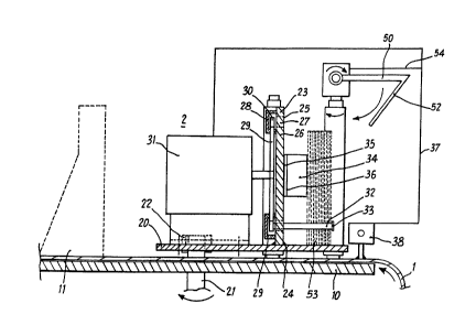
Figure 1 illustrates the device having a manual
5 discharge chain with band transport and temporary stock.ng,
such as it already ~xists in classical machines, being consti-
tuted by an assembly of two narrow bands carrying the refe-
rence number 1 in figure 1. This band is kept in a rotating
movement where~y it is supported by the working table 10
10 within which a non illustrated stud11 is slidingly arranged
in a grove which functions as a stop for the maintenance of
the envelopes in their vertical position. The linking device
2 per se is constituted by a plate 20 which is fixed on a beam
21 which rotates around a bolt 22 which is threaded into
15 its end portion. This plate 2~ comprises further a guiding
plate 23 which is welded at 24 in perpendicular orientation
to the pivoting plate 20. This plate 23 comprises in its
central portion a longitudinal recess 25 which receives a
further plate 26 of complementary profile,having dimensions
20 such that it leaves a free passage 27 between the plate 23
and plate 26 contained therein. The maintenance of this
inner plate is assured by two members 28 and 29 which are
positioned between the two pignons, for example 29, the object
of which is to drive the chain 30 due to the motor 31. A
25 movable bar 32 which is associated to one of the links of the
-~ chain and which carries at its end a small hat 33 of a diameter
superior to the one of the bar itself is designed to carry out
a closed loop movement within the free passage 27 whereby it
is d~iven by said chain 30. The link of this bar 32 may be
30 variable, it may be adapted to the depth of the lot of envelo-
pes which is awaiting its conditioning. Further, during the
piling of envelopes at the output of the snail, it is necessary
to maintain the first vertical ones before the rest of enve-
lopes constituting the lot has arrived. This is the task of
35 a compensator-buffer 34 which is constituted of a spring loaded
steel plate of very small thickness which may be fastened
,. " , ,, :
.--
~33~ 360
4.
to the plate ~6 by any appropriate means such as adhesion
for example at 35. In order to assume the function of a
spring, the plate 34 is folded at 36. The stroke between
its completely folded position and its totally relaxed
position should corxespond to the thickness of the defined
lot of envelopes, i. e. a stroke which corresponds to the
useful links of the bar 32. A counter 38 of the opto-
electronical cell type permits the counting of the envelopes
as they pass by. This counter comprises a link to the
motor 31 such as to control the start of an operation cycle
of this motor corresponding to the movement of a full loop
of the chain carrying the mobile bar 32, once the number
of envelopes corresponding to a lot has been attained.
Another link 54 connects the counter with the
selection finger which will be described further below. Figu-
re 2 illustrates the discharge assembly 5 which comprises as
an essential element a selection finger 50 which is set off
from the front of the lot of envelopes 53 and which is pi-
votingly mounted on the axis 51 such that the bent back por-
tion 52 of this selection finger 50 may abut, after rotation,
onto the envelopes which are schematically illustrated at
53 at the right of the belt 56. The rotation of this selection
finger is carried out by any appropriate means which is
susceptible to be driven by pulses coming from the counter 38.
The object of the selection finger is to abut against the
last envelope of the preceeding lot and to block the envelopes
of the following lot.
The belt conveyor is constituted of two separate
belts 55 and 56 which are mounted such that the planes of
the belts are vertically orientated whereby their movement
is perfectly synchronous- The driving of each belt may be
obtained by a motor-driven roll, whereby a second, associated
roll may assume the role of a tensioner, whereby each belt
comprises a similar couple of rolls. The passage of the belts
~.,,, , , , , , ~ . . ............. . . ........ .
. , , ,:
:, .
.:, . . ...
3L33~
5.
need to be ~ynchronous, however the direction~ of the rotatlon
are inversed to one another such as to obtain the movement
which is represented by arrows 57 and 58, producing a swalo-
wing effect between the two mobile belts . At the exit of
5 this belt conveyor there is provided a pivoting distributor
60 which is mounted on a rotating shaft61 and which compri-
ses twoU-profiles 62 and 63 which are orlented such that
the branches 64 and 65 oppose each other, whereby their flat
portions are horizontally orientated parallel to the plane
10 of the table 10. These two U-profiles comprise a free space
66 between each other corresponding to the width of the
studs 67 which are arranged on the horizontal transport belt
68, the task of which is to discharge the packages of enve-
lopes which are horizontally disposed thereor. after a 90
15 rotation of the distributor in order to be transported to a
non-illustrated conditisning station. Such conditioning ma-
chines may be represented in different embodiments according
to the product to be conditioned, such as for example an
operation whereby the product is covered by a shrinkable
20 film, or by cellophane, or otherwise the application of a
simple band loop realized by a narrow band of cellulose or
any synthetic material, or alternatively the deposition of
those envelopes in a box.
The following is a description of the operation
of a device according to the process proposed by the present
invention.
~he fabricated envelopes are collected at the
30 exit of the machine by the slots of a snail which permits
the vertical positioning of the envelopes which are discharge
from the fabrication machine in horizontal position, whereby
these enveiopes are aligned on the plate 20 whereas the front
face of the first envelope comes into contact with the
35 compensator- buffer 34. Slmultaneously, the counter 38
registers by means of its optical cell, the pulses which are
~1 ~
'
, , , ', ;~
- ,, ~
,: , , '.,' :: : ' .
13~ 36~
6.
created by each passage of an envelope in order to count the
total and, as soon as this total attains a figure correspon-
ding to the desired number of envelopes per lot, a control
signal is sent to the motor 31 by line 37 which provokes
the movement of the mobile bar 32 through the intermediary
of the chain 30 and the pignons. The small hat 33 provides
a security for the lateral seizure of the lots of envelopes.
The envelopes are thus driven in perpendicular fashion by
the bar 32 and slide on the mobile plate 20 and on the plate
of the buffer 34. The counter has meanwhile sent,
via line 54, a control signal to the selection finger 5~
which pivotes as soon as the envelopes have slightly been
moved forwards in a direction perpendicular to the one of
the fabrication exit, whereby the selection finger abuts against
the external surface of the last envelope of the lot. At the
same time, the first envelope of the following lot is already
in place and abutting against the small hat 33 on the one
hand and against the outer surface of the last envelope of
the preceeding lot on the other hand. This first envelope of
the following lot is driven by the friction between the two
faces but this movement is blocked by the portion 52 of the
selection finger 50. It is the main task of this selection
finge~ to delimit the lots from each other and to retain the
first envelopes of the following lot. Its second role is to
slightly compress a lot of envelopes such as to easily intro-
duce the latter between the two belt~ 55 and 56 after positionning
the lots at the starting point of the first belt conveyor.
The synchronous rotations in opposite directions produce
an effect which leads to an insertion of the lot of envelopes
into the space in between the beltsand, due to the frictional
forces, the envelopes are maintained in a compressed condition
between the two belts such as to progress in a direction to-
wards the pivoting distributor.
At the exit of the transport device 5, the enve-
lopes slide into the space between the ~wo opposing U-profiles
62 and 64, the width of which correspond to tfie width of the
lot of envelopesO An appropriated non illustrated end detector
,, . ~ ~
7. ~ 3 ~
permits to trigger a 90 movement of the pivoting distributor
60 leading it to a point above the belt conveyor 68 such
that the studs may seize the lots of envelopes while they
pass across the space 66 between the U-shaped profiles. In
5 the case that an incident in the linking device according to
the present invention is detected by means of a sensor of
a well-known type or by the operator himself, it is possible,
in order to avoid an interuption of the operation and of the
product flow of the fabrication machine, to short-circuit the
! 1 o linking device in favour of a manual output chain with tempo-
rary stocking such as it exist in classical fabrication ma-
chines for envelopes. By means of the belt 1, such systems
transfer the lots of envelopes which come into contact with
a stop 11. The short-circuiting of the linking device is
15 carried out by a rotation of the beam 21 which is fixed to
the pivoting plate 20 such that only the transportation device
5 and the pivoting finger 50 remain in position. These last
mentioned, laterally set offdevices do not hinder in any case
the accumulation of envelopes and the utilisation of the
20 manual system.
It is understood that the present description of
a particular embodiment of the invention does not limit the
scope of the present invention to the above described and
25 represented elements or their shapes. Thus the selection
finger may be supported by the working table 10 or it may
assume another shape such as for example a lateral piston.
Equally, one may provide the transport of the envelopes by
means of a chain and by a device which is positioned at the
- 30 inferior portion of the plate 20 and which may be moved in
a recess in the table 10. The movement of the selected lot
of envelopes may also be obtained by a device comprising a
hydraulical cylinder. Further, the entire operation may
be controlled with respect to the pulses and the different
35 control signals by an associated and appropriately programmed
micro-computer.
~s~
~,",.,,,,.-"~ "- ,, ,,~, - -.:, ~ : ::,- : ,
6 ~
8.
The different pivoting and rocking movements may
be effected by hydraulical or pneumatical cylinders.
For the fabrication of various products, such as
5 mentioned above, the fabrication exits may be provided simply
in a horizontal plane without snail, however, the device ac-
cording to the present invention is applicable after appro-
priate orientation of the components, in particular for
insertion machines.
The present invention is not limited to the
embodiments which have been described above and it may be,
to the contrary, subject to variations and modifications which
appear to the expert in the art.
': ~
,.",. . .. . ..