Note: Descriptions are shown in the official language in which they were submitted.
~ P7258S01/6
~331~29
ZOON LENS BARREL AND C~MERA INCORPO~ING SUCH BARREL
~:, BACKGROUND OF THE DISCLOSURE
;i 1. Field of the Invention
The present invention generally relates to a zoom
5 lens barrel adapted for use in a camera, and more
particularly relates to a zoom lens barrel having a reduced
lens length, which, accordingly, results in reduced camera
thickness when the zoom lens barrel is retracted into a
camera body to which it is attached.
10 2. Discussion of Backaround In~ormation
Recently developed compact cameras have minimized
their width and height dimensions to limits which are
essentially set by the film size and the camera aperture
size. To the contrary, reduction of the thickness of the
15 camera is restricted or limited by the length of the camera
lens when retracted into the body of the camera. When
retracted, the required length of the lens (hereafter also
~ ~ referred to as the 'iaccommodation length") increases as the
;~ displacement of the groups of lenses in the zoom lens
20 increases, resulting in the need to use a longer cam ring to
move the lens groups. Thus, if reguired displacement of the
~ lenses in the lens group is not equal to the desired length
"~;~ of the cam ring, it is possible that even when the lens is
retracted, the cam ring will still project outwardly from
25 the camera body, thereby resulting in a relatively large
thickness camera.
Thus, one primary object of the present invention is to
~ provide a zoom lens barrel in which the thickness of the
r,`~ camera~in which the;lens is positioned, when the Iens is
30 retracted or accommodated,~ can be decreased without
" decreasing the accuracy or precision of movement of the
lens.
The present inventor has recognized that one present
obstacle or bar to reducing the thickness of the camera is
35 the use of a cam ring which rotates at a fixed axial
position to move the lenses in a lens group between a
:: ~
" ,~
r~
P7258S01/6 1 3 3 1 ~ 2 9
photographing position and a lens accommodating (or
retracted) position within a conventional lens barrel.
Accordingly, the present invention is at least partially
directed to solving the above-noted problem, i.e., it is
5 directed to overcoming and eliminating the above-mentioned
obstacle. In other words, the present invention provides a
zoom lens structure without using a cam ring which rotates ~-
at a fixed axial position.
S~lMARY OF THE INVENTION
The present invention includes, in one aspect, a cam
ring which is rotatably supported by a statianary barrel so
~ that the cam ring will move in the optical axis direction in
:~ accordancejassociation with rotation of the cam ring. The
cam ring can be provided with at least two cam grooves for
15 front and rear lens groups in order to determine the
~; displacement of the lens groups.
With this arrangement of a zoom lens barrel, because ;~
the cam ring moves along the direction of the optical axis
~ during rotation of the cam ring, displacement of the lens
.,
20 groups, which is determined by the profiles of the
respective cam grooves, can be increased. In this manner,
it is possible to shorten the accommodation length of the !';;;~
~; lens to which the lens group is retracted tbeyond the ~-~
zooming range). This permits the overall thickness of the .. -
25 camera to be desirably reduced. `
An object of a related i~vention is to provide a
light intercepting element which is designed to prevent
harmful light from reaching the film plane, particularly
when a zoom lens is in its TELE extremity position. This is ;r
30 achieved by providing a light intercepting plate which is ~ `-
formed as a rad~ial extension of a linear movement lens guide
plate located rearwardly of the two lens groups. `
` ~ ~Yet another object of the present invention is to
provide a mechanism for detecting the angular position of a
35 rotatable cam ring. A ~code plate is used which can be
. positloned at a desired angle (or perpendicularly) with
- 2 -
....
' ."~
::
P7258SOl/6 ~ 3 3 1 ~ 2 ~
, I , .
respect to the optical axis; and the mechanism can be
located at several alternate positions within the lens
barrel.
Still another object of a related invention is to
5 correct autofocus detection and measurement in a
microphotography mode. This is achieved by providing a
selectively movable optical element which is rotatably ;,~,~
spring biased into a position in front o~ a light receiving
element of an autofocus system, by using the helicoidal
10 threads attached to the outer periphery of a cam ring.
A further object of a related invention resides in a
system for guiding movement of a flexible printed circuit
~; board. The FPC board is bent over itself to form several ~i
loops, and can be adhesively (or otherwise, e.g., by a
l5 mechanical member) connected to camera components at`spaced
locations. The FPC board is positioned to avoid interfering
with camera components and operation. ~;
A still further object of a related invention is to
- guide movement of a lens guide ring. This can be achieved,
20 e.g., without undue mechanical tolerances, by securing a
plate with deformable portions to the guide ring. -~
Another object of a related invention is to easily
open and close a shutter barrier mechanism. This is
l . .
accomplished via the relative axial displacement, e.g.j of a
¦ ``~ 25 cylindrical lens cover with respect to a lens guide ring,
and should be designed to overcome the adverse effects of
any errors which occurred during the manufacture and/or
assembly of camera components.
Still an additional object of the related inventionsis
` 30 to avoid undesirable engagement between threaded rotating
componentjs of~a camera, by designing tolerances into
threaded areas (e.g., by using inclined surfaces) to ;
facilitate threading engagement and to avoid blocking type ~;
` engagement.
A further object of a related invention is to be able to
` easily provide a focused image on a film plane, e.g., by -
_ 3 _
., :.-
~ P7258S01/6 1331~29
using a tool for flange back adjustment which can be easily
manipulated, even after camera assembly.
According to another aspect of the present invention, a
zoom lens barrel is provided which comprises a stationary
5 barrel, a rotatable cam ring which is supported by the
stationary barrel to move in an optical axis direction in
accordance with rotation of the barrel, and a lens guide
ring which moves together with the cam ring along the
optical axis direction and which is rotated relative to the
10 cam ring in accordance/association with axial and rotational
movement of the cam ring. Cam grooves are provided on the
cam ring for each of at least two movable front and rear
lens groups. Lens guide grooves are formed on the lens guide
~ring in order to correspond to the cam grooves of the cam
;~15 ring, and at least one guide pin is provided which extends
through an associated cam groove and an associated lens
guide groove. The cam grooves and the lens guide grooves
are shaped such that the movable lens groups can be moved
along a predetermined track by the movement which results
20 from the axial movement of, and relative rotation between,
the cam ring and the lens guide ring.
Nith such an arrangement, because the cam ring is
advanced while rotating, the angle of inclination of the cam
grooves can be decreased from what they would need to be if
25 the cam ring only rotated in a single axial position. This
contributes to providing for highly precise movement of the
lens groups. Specifically, when the zoom lens barrel has a
zooming section and a macro transfer section, in which the
lens group is moved from one extreme zooming position to the
30 macro-photographing range, the lead angles, i.e., the
inclination angles of the cam grooves of the zooming section
and the macro-transferring section, can be oriented so that
`~ they are opposite to each other with respect to a direction
which is parallel to the optical axis.
35In accordance with the present invention, because the
~;~ cam ring and the lens guide supporting the lens groups move
_ 4 _
~ .. `,'~`'~
~ ~ P7258S01/6 1331~2~ ~
the lens groups along the optical axis direction, and
because the lens groups can be moved along the optical axis
direction by relative movement of the cam ring and the lens
guide ring, the accommodation length of the movable lens
5 groups can be shortened, thereby resulting in a camera which
is compact, small and thin. Further, in accordance with the
present invention, a relatively large axial displacement of
the cam ring, resulting from both angular and axial
displacement of the cam ring, can be ensured.
10 Additionally, the axial displacement of the movable lens
groups relative to angular displacement of the cam ring can
be decreased by using a lead angle of the cam groove of the
macro-transferring section which is opposite to the
direction of that in the zoom section with respect to the
15 optical axis, thereby resulting in more precise movement of
the movable lens groups.
Specifically, because the cam ring and the lens guide
ring, which rotates relative to the cam guide ring, move
along the direction of the optical axis while supporting the
20 lens groups, so that resultant movement of the cam ring and
the lens guide ring will effect axial movement of the lens
groups, it is possible to increase displacement of the lens
groups along the optical axis, in the normal photographing
(i.e., zoom) range, even while using a cam ring and lens
25 guide ring with decreased or reduced optical axial lengths;
thus, a camera incorporating the same will have a relatively
small thickness with an increased photographic (focal
length~) range. Further, because the cam grooves have
opposed~ lead angles which are inclined in opposite
30 directions with respect to a direction which is parallel to
the! optical axis of the zooming section and a macro~
trans~erring section, displacement of the lens groups can be
decreased in comparison to the angular displacement of the
cam ring, thereby resulting in highly precise movement of
35 the lens groups, i.e., greater angular displacement can
result in increased precision of resultant axial lens
- 5 -
:~ '';~,'. ':
P7258S01/6
-` 1331429
movement.
BRIEF DESCRIPTIONS OF THE DRAWINGS
The above and other objects, features and advantages of
thP present and related inventions will be dis ~ sed in greater detail ;
5 hereinafter with specific reference to the drawings which
are attached hereto, in which like reference numerals are
used to represent similar parts throughout the several
views, and wherein:
Fig. 1 is a longitudinal sectional view of the upper
lO half o~ a zoom lens barrel capable of macro-pho!tography,
;~ shown in a position in which the lenses are retracted or
accommodated, according to one embodiment of the present
invention;
Fig. 2 is a view which is similar to Fig. 1, with the
15 apparatus shown at a WIDE extremity position;
Fig. 3 is a view similar to Fig. 1, with the apparatus
shown at a TELE extreme position;
Fig. 4 is a view similar to Fig. 1, with the apparatus
shown at a MACRO photographing position;
~;~ 20 Fig. 5 is a developed or plan view of a cam ring, a ~;~
lens guide ring, and an inner helicoid ring;
Fig. 6 is an explanatory or schematic view illustrating
the relationship between displacement of the cam grooves and ;~
the lenses;
Fig. 7 is an explanatory view illustrating the ~;;
relationship between the cam grooves and the lenses in a
known camera, and is labeled as prior art; -
;~ Fig. 8 is a perspective view of a brush provided on an
outer helicoidal element in order to detect the angular
30 position of a cam ring;
~ Fig. 9 is a plan view of a code plate which is placed
`~ into sliding contact with the brush on the helicoid
~` ` illustrated in Fig. 8; `
Fig. 10 is a longitudinal sectional view of a zoom lens
35 barrel illustrating a mechanism for detecting the angular ~-
position of a cam ring, similar to the view shown in Fig. 1, ` ;
- 6 - .
,
: ,'.. , ;~:
'.,.~''".'",
S '.'`.`.''~,"
P7258S01/6
~ 133~29
according to a second embodiment of the present invention;
Fig. loA is a longitudinal sectional view of a zoom
lens barrel illustrating an alternate (third) embodiment of
the mechanism of Fig. l;
Fig. 11 is a developed or plan view of the angular
position detecting mechanism illustrated in Fig. 10, a cam
ring, a lens guide ring, and an inner helicoid ring;
Fig. 12 is an exploded perspective view of the zoom
lens harrel which is shown in Figs. 1-4, and of a close
10 distance (i.e., macro) correcting mechanism for an object
distance measuring device;
Fig. 13 is a front elevational view of the apparatus
illustrated in Fig. 12;
Figs. 14A and 14B are a front elevational view of the
15 close distance correcting optical element shown in Fig. 12,
in inoperative and in operative positions, respectively;
Fig. 15 is a partially cut away or broken prospective
view of a mechanism for housing a flexible printed circuit
board connected to the shutter unit of a zoom lens barrel,
~ 20 as shown in Figs. 1-4;
; Fig. 16 is a cross-sectional view of the mechanism of
Fig. 15;
Fig. 17 is an exploded perspective view of the zoom
lens barrel illustrated in Figs. 1-4, in combination with a
25 light barrier mechanism;
Figs. 18A and 18B are longitudinal sectional views of a
zoom lens barrel having a barrier mechanism as shown in Fig.
17, and is shown in a closed position in which the barriers
are closed and an open position in which the barriers are
30 open, respectively;
Figs. 19A and l9B are front elevational views of the
barrier mechanism illustrated in Fig. 17, corresponding to
the views of Figs. 18A and 18B, respectively;
Fig. 20 is a longitudinal sectional view of a lens
35 barrel driving mechanism as shown in Figs. 1-4;
Fig. 21 is a developed or plan view of the lens barrel
P7258SO1/6 1 3 ~ 2 9
driving mechanism shown in Fig. 20, a cam ring, a lens guide
ring, and an inner helicoid;
Fig. 22 is a perspective view of the main portion of a
lens barrel driving mechanism;
Fig. 23 is an exploded perspective view of the main
elements which are illustrated in Fig. 22;
Fig. 24 is an enlarged perspective view of a maln
portion of the structure of Fig. 23;
Fig. 25 is a developed or plan view of the structure
10 illustrat~d in Fig. 24;
Fig. 26 is an exploded perspective view of a zoom lens
barrel mechanism as shown in Figs. 1-4, in combination with
a flange back adjusting mechanism;
Fig. 27 is a front elevational view of a part of the
15 mechanism of Fig. 26, illustrating adjustment of the flange
back using an adjusting tool;
Fig. 27A is a front elevational view of an alternate
mbodiment of the mechanism illustrated in Fig. 27;
Fig. 28 is a perspective view of a camera having a
20 flange back adjusting mechanism; and
Fig. 29 is a longitudinal sectional view of a zoom lens
barrel including the flange back adjusting mechanism
illustrated in Fig. 26.
DETAILED DESCRIPTION OF THE DRAWINGS
The present and related inventions will now be discussed in
greater detail with specific reference to the drawings which
are attached hereto.
In the~illustrated embodiment, the present invention is
used~in a zoom lens barrel ~having a macro photographic
- 30 function; although many of the features can equally well be
used in a camera~without such a function. Figs. 1, 2,'3~and
4 illustrate the lens in a retracted position, a WIDE
extremity positi~on, a TELE extremity position, and a MACRo
photographing position, respe`ctively. It can thus be easily
` ` 35 understood from the drawings of Figs. 1-4 (and particularly
` Fig. 1) that the accommodation or retracted length of the
8 ~
`P7258S01/6
1331429
lens barrel in accordance wi~h the present in~ention is
small.
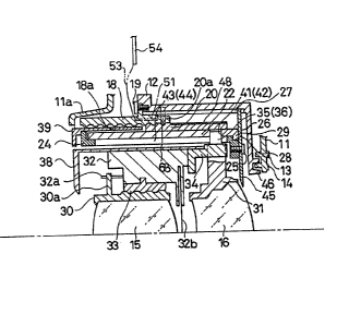
As illustrated in Fig. 1, a stationary ~arrel 12 is
secured to a camera body 11, preferably of a lens shutter
5 type of zoom lens camera as disclosed in commonly assigned
c~-pending U.s. Application 144,030, the disclosure of which
is expressly relevant herein. The camera
body 11 includes an outer rail 13 and an inner rail 14,
respectively, which serve as a film guide. Inner and outer 1-
10 rails 13 and 14 further define a film holding plane. In the
illustrated embodiment, front and rear lens groups 15 and
16, respectively, can be retracted to, and accommodated
~`~ within, a position which is very close to the film holding
plane. Additionally, annular members such as cam ring 22
15 are relatively small, and, accordingly, the accommodation
length of the camera can be decreased.
A female helicoid ring 18 having inner peripheral
helicoid teeth or threads 18a is secured to, and inside of,
stationary barrel 12 by set screws 19. The female helicoid
~; 20 ring 18 is screw/ threadably engaged by a male helicoid ring
20 having outer peripheral helicoid teeth or threads 20a.
Cam ring 22 is secured to male helicoid ring 20 by set
screws 21, as illustrated in Fig. 5.
A gear 20b is formed on the outer periphery of male
25 helicoid ring 20; the gear has threads or teeth, each of
which extends parallel to the optical axis, as illustrated `
in Fig. 5. Gear 20b extends at the same angle of
inclination as the lead anyle of helicoid teeth 20a of male
helicoid ring 20, i.e., it is parallel to the-direction of
30 each of the teeth or threads 20a, as shown in Figure 5. Cam
;ring 22 is rotated in both forward and reverse directions by
a driving motor, described in detail hereinafter, through a
pinion which meshes with gear 20b, so that when the male
helicoid ring 20 is rotated, cam ring 22 is moved in the
35 optical axis direction in accordance with the lead angle of
helicoid teeth 20a, all while the cam ring is rotating.
_ g _
P7258S01/6 1 3 3 1 ~ ~ 9
Lens guide ring 24 is ~itted into the inner periphery
of cam ring 22 50 as to move together with cam ring 22 along
the optical axis direction, and so that it will rotate
relative to cam ring 22. Lens guide ring 24 includes a
5 linear movement guide plate 26 which is secured to the rear
end of the lens guide ring 24 by set screws 25. Linear
movement guide plate 26 includes at least one outer
projection which are each engaged in a respective lens guide
ring guide groove 27 formed on the interior surface of
10 stationary barrel 12. As one example, four projections and
grooves are shown in Figure 16. Each guide groove 27 is
provided in the form of a straight groove, which extends
along (i.e., parallel to) the optical axis direction in the
embodiment which is shown in the figures.
An annular groove 28 is provided between the linear
movement guide plate 26 and the rear end of lens ~uide plate
24; an inner flange 29 on the rear end of cam ring 22 is
:: relatively rotatably fitted within annular groove 28, so
that lens guide ring 24 can move along the optical axis
20 direction together with movement of cam ring 22. Guide ring
24 cannot, however, rotate, due to the presence of guide
groove(s) 27, which engages plate 26 to prevent rotation.
Cam ring 22 can, of course, rotate relative to (and about)
lens guide ring 24.
Front and rear lens groups 15 and 16 are secured to
front lens group frame 30 and rear lens group frame 31,
respectively, which are both located inside the lens guide
ring 24. Front lens group frame 30 is connected to helicoid
ring 33, which is itself secured to shutter block 32. The
30 shutter block is secured to a front lens group moving frame
34, which is provided along its outer periphery with at
least three guide pins 35. Rear lens group frame 31 is
provided along its outer periphery with at least three guide
pins 36. As illustrated in Figs. 1 and 3, the guide pins
35 are shown at the same axial positions, thereby making it
possible to show only one such pin; Figures 2 and 4,
-- 10 --
,;
58501/6 1 3 3 1 4 2 g
however, illustrate the pins at axially spaced positions (as
does, e.g., Fig. 17).
Shutter block 32 rotates driving pin 32a over an
angular displacement corresponding to an object distance
5 which is detected by an object distance measuring device
(not illustrated) in order to rotate the front lens group
frame 30, which is associated with driving pin 32a, via pin
30a. In this fashion, front lens group ~rame 30 is moved
along the optical axis direction in accordance with movement
10 of the helicoid in order to effect focusing, in a well-known
fashion. Shutter block 32 also operates shutter blades 32b
in accordance with a signal representing the brightness of
an object which has been detected.
A cylindrical lens cover 38 is provided which is
15 integral with front lens group moving frame 34, and a
~ decorative cylinder 39 is provided which covers the outer
¦ peripheries of lens guide ring 24 and cam ring 22, which are
adapted to respectively project from the outer shell lla of
the camera body.
Cam ring 22 is provided with a front lens group cam
groove 41 and a rear lens group cam groove 42 within which ;-
guide pins 35 and 36, respectively, are fitted. Lens guide
ring 24 is provided with lens guide grooves 43 and 44 which,
respectively, correspond to the front lens group cam groove
25 41 and the rear lens group cam groove 42. As shown in the
embodiment of Figs. 1-4, lens guide grooves 43 and 44 are
straight grooves which extend in the direction of the 1
optical axis. Guide pin 35 extends through both the front
lens group cam groove 41 and the lens guide groove 43, and
30 guide pin 36 extends through both the rear lens group cam
1 groove 42 and the lens guide groove 44.
¦ The profiles of front lens group cam groove 41, lens
guide groove 43, and rear lens group cam groove 42, as well
as lens guide groove 44, are determined such that movable
35 lenses or lens groups 15 and 16 are moved along a
predetermined axial track in accordance with the axial
-- 11 --
..
.. ~ ,., .. , . ,.. . . .. ...... . .. , .. ... . .. . .. . ., . . - - -
P7258S01/6 ~ 3 3 1 ~ 2 ~
!
movement of cam ring 22 and lens guide ring 24 effected by
rotation of the male helicoid ring 20, and by relative
rotation of cam ring 22 with respect to lens guide ring 24.
As shown in Fig. 5, the section ~ 1 of the front lens
5 group cam groove 41 and the rear lens group cam groove 42
represents the normal photograph:ing range (i.e., the zooming
section), section R 2 represents the MACRO transferring
section, which is connected to the TELE extremity position
of zooming section R 1, and section Q 3 represents a lens
10 accommodating or retracted sect:ion connected to the WIDE
extremity position of zooming section Q 1, respectively.
MACRO transferring section ~ 2 has a lead angle which is
opposite to the angle of inclination of zooming section
R 1, with respect to a dir~ction which is parallel to the
15 optical axîs. Specifically, assuming that the lead angle of
the zooming section Q 1 is positive (+), then the lead
angle of the MACRO transferring section Q 2 will be
negative (~
The zoom lens as constructed operates as detailed
20 hereinafter.
When male helicoid ring 20 is rotated in forward and
reverse directions, the male helicoid ring 20 will move
along the optical axis direction while rotating, in
accordance with the lead angle of helicoid teeth 20a, since
25 the female helicoid ring 18 which is engaged by the male
helicoid ring 20 is secured to stationary barrel 12.
Namely, cam ring 22, which is secured to male helicoid
ring 20, is rotated together with the male helicoid ring 20
and will be moved along the optical axis direction in
30 accordance with the lead angle of the helicoid teeth 20a.
Further, lens guide ring 24, which is mounted to cam
ring 22 so that the two rings will rotate with respect to
each other and move together along the optical axis
direction, is moved along the direction of the optical axis,
35 without rotating, in accordance/association with axial
movement of cam ring 22. Relative rotation of cam ring 22
- 12 -
''~' ~',"`
.-,'~.,''-'"
P7258SOl/6 1 3 3 ~ ~ 2 ~
and lens guide ring 24 causes axial movement of moving
lenses 15 and 16 in accordance with the relationship between
cam groove 41 and lens guide groove 43, as well as in
accordance with the relationship between cam groove 42 and
5 lens guide groove 44. Movement of the two lens groups is
best illustrated in Figure 6. As shown, rings 22 and 24
move over substantially the same distance along the
optical axis direction.
Thus, lenses 15 and 16 can be moved from the
lQ accommodation position, as shown in Fig. 1, to the macro-
photographing position, which is illustrated in Fig. 4, as a
result of the movement of cam r:ing 22 and lens guide ring
24. Thus, it should be appreciated that when in the
accommodation position, the accommodation length of the lens
15 is extremely small, since the cam rin~ 22 and lens guide
ring 24 do not protrude outwardly from the outer shell lla
of the camera body or from the cylindrical lens cover 38.
Specifically, cam ring 22 rotates and moves ~long the
optical axis direction in accordance with the lead angle of
20 helicoid teeth 20a. Accordingly, the axial lengths of cam
grooves 41 and 42 can be shorter than the largest axial
displa~ement Ll of lenses 15 and 16, by an amount which
corresponds to the axial displacement L2 of cam ring 22, as
shown in Fig. 6. In other words, the total length of cam
25 ring 22 can be shorter than the largest displacement L1 of
the lenses by an amount which corresponds to the axial
displacement L2 of cam ring 22.
On the other hand, as shown in the schematic
representation of the prior art structure of Fig. 7, known
30 cam ring 50 does not move along the optical axis direction.
Consequently, in such a known cam ring 50, the axial lengths
of cam grooves 51 and 52 correspond to the axial
displacement of the moving lenses (i.e., to the movement of
cam pins 53 and 54), and, accordingly, the axial length of
35 cam ring 50 must be equal to or greater than the largest
displacement of the lenses.
- 13 -
P7258S01/6
13~1~29
In the present structure, even if lens displacement
effected by cam grooves ~1 and 42 is decreased by reducing
the lead angles of cam yrooves 41 and 42, axial displacement
effected by the lead angle of the helicoid teeth 20a will
5 not change. Specifically, assuming that the lead angles of
cam grooves 41 and 42 are zero, the displacement of lenses
15 and 16 with respect ko cam ring 22 will also become zero,
but lenses 15 and 16 will be finally moved by a displacement
which corresponds to the lead angle of helicoid teeth 20a,
10 insofar as cam ring 22 will axially move in accordance with
the lead angle of helicoid teeth 20a as shown in Fig. 6.
Thus, even if the rear lens group cam groove 42 is
provided in a plane which is perpendicular to the optical
axis, lens 16 can be retracted into the accommodation
15 position by rotating cam ring 22. This means that the lead
or inclination angles of the rear lens group cam groove 42
and the lens guide groove 44 formed on cam ring 22 can be
significantly reduced, so that the axial lengths of rear
lens group cam groove 42 and lens guide groove 44 can be
20 reduced in order to shorten the cam ring 22 and so as to
increase the resulting accuracy of movement of moving lenses
15 and 16, as discussed hereinafter.
The relationship between the lead angles and the cam
grooves 41 and 42 becomes clear when looking at
25 accommodation section R 3 of rear lens yroup cam groove
42. Section Q 3 of groove 42, as seen in Fig. 5, is
oriented so that it is perpendicular to the optical axis of
cam ring 22. If cam ring 22 could only rotate, and could
not also move in the optical axis direction, as is the case
30 with the known cam ring of Figure 7, moving lenses 15 and 16
could not be retracted. However, in accordance with the
present invention, since cam ring 22 can move along the
optical axis direction, it is possible to retract moving
lenses 15 and 16 even when the groove (i.e., slot~ is
35 perpendicular t:o the optical axis, unlike the situation with
the illustrated prior art structure.
- 14 -
P7258SOl/6 ~L 3 3 1 ~ ~ ~
It is important to remember that the necessary
displacement of lenses 15 and 16 from the TELE extremity
position to the macro-photographing range is very small in a
zoom lens barrel as used in accordance with the present
5 invention. In order to decrease the displacement of lenses
15 and 16, yet still achieve necessary displacement of the
lenses, excess displacement is eliminated by the disclosed
configuration of cam grooves 41 and 42. Specifically, the
lead angles of macro-transferring section 2 of cam grooves
10 41 and 42 are negative (-) to provide a negative (-) lead
angle. This results in the shorter displacement L4 of rear
lens group 16 (i.e., of guide pin 36) with respect to the
axial displacement of cam ring 22 in the macro-transferring
section ~ 2, than occurs in the zooming section R 1.
15 That is, the displacement of moving lenses 15 and 16 with
respect to angular displacement of cam ring 22 can be
reduced, as shown in Fig. 6. With such an arrangement,
since the displacement of lenses 15 and 16 relative to the
angular displacement of cam ring 22 is very small, it is
20 possible to provide a sufficient angular displacement of cam
ring 22 so as to result in highly precise movement of the
lenses. Further, since the lead angle of the macro-
transferring section Q 2 is minus (e.g., a negative), the
total length of cam ring 22 can be reduced.
In the illustrated embodiment referred to above, guide
groove 27, as well as lens guide grooves 43 and 44, are all
straight grooves. However, it should be appreciated that
the present invention is not limited to the use of such
straight grooves. Specifically, the present invention does
30 not exclude, prevent, nor eliminate the possibility of
providing guide groove 27 and lens guide grooves 43 and 44
of shapes which are other than straight, e.g., of an angled
configuration. To summarize, the shapes of guide groove 27,
cam grooves 41 and 42, and lens guide grooves 43 and 44 are
35 determined so that the lens guide ring 24 will move along
the optical axis direction, together with the cam ring 22,
- 15 -
f P7258SOl/6
3 ~L331~2~
in accordance with rotation o~ the cam ring, and so thatlenses 15 and 16 will move in the optical axis direction,
along a predetermined track, in accordance with relative
rotation (and axial movement) of cam ring 22 and lens guide
5 ring 24.
It should be noted that lens guide ring 24 could be
provided to rotate if desired. This could be accomplished,
e.g., by forming lens guide groove 27 at a predetermined
angle of inclination with respect to the optical axis,
¦ 10 rather than parallel thereto, as is shown in Fig. 5. Even
I if ring 24 is rotatable, however, rings 22 and 24 can still
be rotatable with respect to each other, since they can be
I formed so as to rotate over different angular amounts with
¦ respect to each other.
At least three guide pins 35 and at least three guide
pins 36 are provided (in engageable association with cam
grooves 41, 42 and lens guide grooves 43, 44) in order to
prevent rear lens group frame 31 and ~ront lens group moving
~rame 34 from being inclined with respect to the optical
20 axis, which might occur due to the otherwise insufficient
length of engagement with respect to lens guide ring 24.
Thus, if a sufficient engagement length can be provided, or
if there is the possibility that the incline of rear lens
group frame 31 and front lens group moving frame 34 can be
25 eliminated by providing additional guide poles or similar
structure, the number of guide pins can be reduced to either
one or two.
Although the male helicoid ring 20 and the cam ring 22
are formed of separate members which are interconnected by
30 set screws 21, in the illustrated embodiment, they could
alternatively be molded as a single integral piece of
synthetic resin or similar material.
The above discussion was directed to the basic overall
construction and operation of a zoom lens barrel in
35 accordance with the present invention. The following
descriptions will address additional lens mechanisms or
- 16 -
~P7258So1/6
31~29
;components and combinations thereof, in accordance with
;6o-ther aspects of the present and related inventions.
3B. Liaht Intercept~a~ Mechanism
A light intercepting plate 45 is positioned at the rear
5 end of lens guide ring 24. This intercepting plate is
adapted to intercept harmful light which would otherwise
enter the lens barrel, along the inner peripheral wall o~
the lens barrel, from the circumferential portion of moving
lens 16, and which would have an adverse influence on the
10 formation of an image on the film plane. In the illustrated
embodiment, the light intercepti;ng plate 45 is formed by a
radial extension of the linear movement guide plate 26,
which extends in a direction away from the inner surface of
barrel 12, and which is normal to the optical axis. The
15 inner end of the light intercepting plate 45 is lacated in a
position which generally corresponds to the circumferential
portion of lens 16, as shown in Figure 2. If harmful light
enters the lens barrel from the circumferential portion of
lens 16, through the inner wall of the lens barrel, light
20 will be reflected by the inner wall of the lens barrel and
will reach the film plane through aperture 46. This will,
in turn, cause a number of undesirable problems, e.g., a
reduction of image contrast or a decrease in the coloring
characteristics of color film. Such a phenomenon tends to
25 occur particularly when the lens is located in the TELE
extremity position. Namely, when in the TELE extremity
¦~ position, moving lenses 15 and 16 are fed forwardly (i.e., :~
¦ advanced) the farthest, and, accordingly, the internal space
of the lens barrel is expanded. As a result, harmful light
l 30 passing the circumferential portion of lens 16 is diffused
within the expanded internal space of the lens barrel.
!~ ' Consequently, harmful light is reflected in a complicated
fashion by the inner wall of the lens barrel and reaches the
film plane. Light intercepting plate 45 thus effectively
35 intercepts harmful light which would otherwise reach the
film plane, as noted above, particularly when the lens is in
- 17 - ~
:~,
' ~:
P7258S01/6
--` 1331~2~
the TELE extremity position. While shown as integrally
attached to plate 26, it is alternately possible to provide
a light intercepting plate 45 which is separate from guide
plate 26, and/or which is attached to other camera
5 structure.
c. Detectinq Mechanism of Focal Lenqth Information - First
Embodiment
A first mechanism which is provided for detecting
focal length information is adapted to detect the angular ;-
10 position of the cam ring 22 in order to detect zoom lens -
focal length information. The mechanism is attached to the
periphery of one ring (or an attachment thereto) which is ~-
relatively rotatable with respect to a second ring, so that
relative rotation can be detected. -
15As shown in Figures 1-5, a code plate 48 is attached to
cam ring 22 indirectly, i.e., it is attached to the outer
periphery of male helicoid 20 which is attached to the cam ~- ;
ring. Plate 48 is secured to helicoidal ring 20 by set
screws 49 and is inclined at an angle which is identical to
20 the angle of inclination (with respect to the optical axis)
of helicoid teeth or threads 20a. Outer helicoid 18 is
provided, along its inner periphery, with a brush securing
recess 50 (see Fig. 8) which corresponds to code plate 48.
Recess 50 can be inclined, as shown, at the same angle as
25 the angle of inclination of each of the helicoid grooves 18a
(it is not so inclined, e.g., in the embodiments of Figs.
10, 10A, and 11). Brush 51, having a base portion 52, is
secured to recess 50 so that it will always come into -
sliding contact with code plate 48. Brush 51 is positioned
30 so that it is substantially parallel to the length of code
plate 48. Code plate 48 and brush 51 together comprise a
detecting mechanism for detecting the angular position of
cam ring 22, i.e., for detecting information relating to the
focal length of the zoom lens, the accommodated position of
35 the lenses, ancl the WIDE and TELE extremity positions of the
zoom lens. Code plate 48 includes conductive lands 48a and
- 18 - -~
P7258S01/6 1 3 3 1 ~ 2 ~
./ . .. `
3 nonconductive lands 48b, as best illustrated in Fiy. 9.
Brush 51 includes one common terminal 51a and three
terminals 51b, so that when terminals 51a and 51b come into
contact with the conductive lands 48a of code plate 48, a
5 signal "0" will be output, and, when the terminals do not
come into contact with conductive lands 48a, a signal "1"
will be output. The relative angular position of cam ring
22 and lens guide ring 24 can ble detected by a combination
of signals "1" and "0". Base portion 52 of brush 51 is
lO connected to control board 54 through flexible printed
circuit (FPC) board 53.
Code plate 48, which comprises part of the angular
I position detecting mechanism, can be inclined with respect
¦ to rings 20 and 22, at an angle which is identical to the
15 angle of inclination of helicoid teeth 20a, so that the code
plate 48 will move in the same direction as the helicoid
teeth, as noted above, and, accordingly, so that the code
plate 48 will not be a bar or obstacle to reduction of the
I combined length of the lenses.
20 D. Detectinq Mechanism of Focal Lenqth Information - Second
and Third Embodiments
Figs. 10 and ll illustrate a second embodiment of a
focal length information detecting mechanism; in this
¦ embodiment, the mechanism is also attached to a ring which
¦ 25 is relatively rotatable with respect to a second ring. The
first focal length information detecting mechanism (1)
referred to above is positioned between helicoidal ring 18
and cam ring 22, and is directly attached to the outer
periphery of ring 20. Alternatively, the second focal
30 length information detecting mechanism (2), as described in
this section, is provided between lens guide ring 24 and a
bent portion of plate 26, which is attached to a rear
surface of cam ring 22. In this embodiment code plate 48A
is not inclined with respect to the optical axis, but is
35 directly positioned on the outer periphery of cam ring 22 so
that it is concentric with ring 22 about the optical axis.
- 19 ~
,',~,' ~"'
~ P7258Sol/6 ~ 3 3 1 ~
Code plate 48A is secure~ ~o the outer periphery o~ the
rear end of cam ring 22 by set screws 49A (see Fig. 11).
j Brush 51A, which includes a base portion 52A connected to a
¦ brush securing member 55 positioned above the code plate
5 48A, is in continuous sliding contact with code plate 48A.
Brush securing member 55 is formed by bending a portion of
the guide plate 26, which is secured to the rear end of lens
guide ring 24, so that the securing member is parallel with
the optical axis. Code plate 48A and brush 51A together
10 comprise a detecting mechanism for detecting the angular
position of cam ring 22, i.e., for detecting zoom lens focal
length information, the accommoclated position of the lens,
and the WIDE and TELE extremity positions of the zoom lens.
The construction of both code plate 48A and brush 51A are
15 essentially the same as those of the above-noted focal
length detecting mechanism (1), as illustrated in Fig. 9.
Base portion 52A of brush 51A is connected to control board
54A through a flexible printed circuit board 53A. As can
readily be understood from the above discussion, the focal
20 length information detecting mechanism is thus fùnctionally
(although not physically) positioned between cam ring 22 and
lens guide ring 24. If desired, the mechanism could be
physically positioned between rings 22 and 24, if adequate
clearance is provided.
The third embodiment of the angular position detecking
mechanism (i.e., focal length detector) is illustrated in ~;
Figure lOA. In this Figure, the mechanism is physically
positioned between relatively rotatable rings 22 and 240 As
shown, code plate 48B is positioned on the inner peripheral
30 surface of cam ring 22, with conductive brush 51B (having a
base 52B and suitable bristles) positioned on the exterior
! surface of ring 24 (although the plate and brush could
alternatively be oppositely disposed). Thus, relative
rotation of the rings, as in the above embodiments, effects
35 continuous slicling contact of brush 51B and plate 48B, and
together definle a detecting mechanism for detecting the
- 20 -
. ~:
P725~SOl/6
13314~
angular position of cam ring 22.
E. Operation Mechanism or the Close Distance correctinq
O~tical Element
As illustrated in Figs. 12-14, the stationary
5 barrel 12 has, at its front end, a lens barrel support plate
12a which lies in a plane which is normal to the optical
axis. A zoom motor 12c, having a pinion 12b at one axial
end, is secured to the upper port:ion of supporting plate 12a
via a securing member which is not illustrated. Pinion 12b
10 is exposed within stationary barrel 12, i.e., it extends
outwardly of the barrel, via a gear window 12d formed in
barrel 12. Lens barrel support plate 12a is provided, along
an upper portion of the plate in the vicinity of gear window
12d, with a supporting recess 12e within which a close
15 distance correcting optical device 60 is also supported.
An object distance measuring device 70 is secured to
stationary barrel 12. This object distance measuring device
detects the object distance in accordance with a photo-
induced current, which depends upon the object distance.
20 The device includes a light emitting portion 71 and a light
receiving portion 72, which is connected to the light
emitting portion 71 by a connecting portion or bridge 73.
The light emitting portion 71 and light receiving portion 72
(which includes, e.g., a PSD [i.e., position sensing device]
25 as a light receiving element) are located on opposite sides
of the zoom motor 12c. Object distance measuring device 70,
which is known per se, detects the object distance based on
the known triangulation measuring principle.
Light emitting portion 71 includes, e.g., a light
`~ 30 source such as an LED, and a projecting lens, and light
receiving portion 72 includes, e.g., a PSD which is spaced
from the light source by a predetermined base length, and a
light receiving lens, as noted above. It should be noted
that the light source, the projecting lens, and the light
35 receiving lens (all of which are not shown) are preferably
provided in a single unit or assembly. Light emitted from
- 21 -
;.~',,'':-
~ P7258S01/6 1 3 3 1 ~ 2 ~
... .
the light source is reflected by the object and is incident
upon the PSD of the light receiving portion 72, on which the
incident position (i.e., the light point) of light on the
light receiving surface depends upon the object distance.
5 The object distance can be detected by the photo-induced
current, which depends upon the light point. An operation
signal, which is sent in response to the detected object
3 distance data, is supplied to shutter block 32 in order to
effect automatic focusing. ~The close distance correcting
10 optical device 60 is supported within supporting recess 12e
of lens barrel support plate 12a so that it will move away
from and approach the light receiving portion 72 of o~ject
distance measuring device 70. The close distance correcting
optical device 60 moves correcting optical element 61 (e.g.,
j 15 a prism) to bring it in front of light receiving portion 72
only in the macro-photographing mode, so that light
reflected from the object is refracted in order to change
the incident position of reflected light onto the light
receiving portion 72 in the macro mode, thereby improving
, 20 object distance measurement accuracy in the macro mode. The
~ correcting optical element 61 is not limited to the
! illustrated embodiment, which is described in detail, e.g.,
in Japanese Patent Application No. 62-42,1~8 published
before the filing date of the present application and filed
25 in the name of the assignee of the present invention, since
the subject of the present invention is not directly direc-
ted to the details of construction of the correcting opti-
cal element 61.
The correcting optical element 61 includes an opening
30 62 on the object side and an opening (not illustrated) on
thè side of the light receiving portion 72. The correcting
optical element 61 also includes a mask 63 which intercepts
light outside of the necessary light path. Opening 62,
which is offset from the optical axis of light receiving
35 portion 72, is provided in the form of a slit. The
correcting optical element 61 has an arm 66, which is
- 22 -
,t`\
' ~'
p7258sol/6 133~ 4 29
' connected to a rotatable shaft 65, which is in turn pivoted
about a pivot shaft 64 secured within supporting recess 12e.
The correcting optical element 61 is rota-tably biased by a
tensile spring 67, so that elem2nt 61 will tend to move in
5 front of the light receiving portion 72. Tensile spring 67
is connected at one end to arm 66 and at an opposed, second
end, to outer helicoid 18 or to an element on the outer
helicoid side. Rotatable shaft 65 is provided on its rear
lowex end portion with an associated projection 68, integral
10 therewith, which includes a front end projecting into the
stationary barrel 12 through winclow 12f OlC supporting recess
12e. Associated projection 68 is briefly illustrated, in
Figs. 1 and 2, by an imaginary line.
Projection 68 is disengagably engaged by one helicoid
15 tooth or thread 69 of inner helicoid 20 in order to move
correcting optical element 61. Helicoid tooth 69 is formed
by an extension of one of the helicoid teeth 20a along gear
20b. The length of helicoid tooth 69 substantially
corresponds to the section of angular displacement of cam
20 ring 22 in which the zoom lens is located between the TELE
extremity and the WIDE extremity positions, so that the
helicoid tooth 69 will have a cutaway portion 69a (see
Figure 14A) which is not engaged by the associated
projection 68 in the macro mode of the camera.
Specifically, the correcting optical element 61 is
located in an inoperative or retracted position in which the
associated projection 68 is engaged by the helicoid tooth
69, so that the correcting optical element 61 is retracted
from the optical axis of light receiving portion 72 in the
30 normal photographing position of the zoom lens, i.e.,
betlween the TELE extremity and the WIDE extremity, as is
well illustrated in Fig. 14A. On the other hand, in the
macro position of the zoom lens, the associated projection
68 is positioned in the cutaway portion 69a, so that the
35 associated projection 68 will be disengaged from helicoid
tooth 69, and such that the correcting optical element 61
- 23
P7258SOl/6 :L 3 3 1 ~ 2 9
!~ will be brought in front of the light receiving portion 72
~ as shown in Fig. 14B.
`~ With such an arrangement for a close distance
correcting mechanism, movement of correcting optical element
5 61 towards the front end of the light receiving portion of
the object distance measuring device can be ensured by the
noted configuration of the helicoid tooth 69 which is
provided on cam ring 22. Accordingly, no special element
needs to be additionally provided, thereby providing a
10 relatively simple operating mechanism for selectively
positioning the optical element 61 in front of the light
receiving elemenk 72 during macro photography.
F. Guide Mechanism for the Flexible Printed Circuit Board
The following discussion is directed to a guide
15 mechanism for the flexible printed circuit board 81, which
supplies an operating signal to shutter block 32.
As illustrated in Fig. 3, the flexible printed circuit
board 81 is connected to control circuit board 54, and is
positioned or introduced within a space defined by
l 20 stationary barrel 12 and cam ring 22 through a window formed
~ in stationary barrel 12. The flexible PC board 81 is then
I extended rearwardly within the space located substantially
- along the inner surface of stationary barrel 12, so that it
is introduced rearwardly through the gap which exists
25 between projections 26a of the linear movement guide plate
¦ 26. The flexible PC board 81 is then bent forwardly, at a
first bent portion 81a, and extends along the outer surface
of guide plate 2~ and along the inner circumference thereof,
in a generally forward direction.
Lens guide ring 24 is provided, along its inner
periphery, with a substantially linear (flexible PC board)
guide groove 8~ having a bottom or base extending along
~i.e., parallel to) the optical axis direction, as shown in
Fig. 15. The flexible PC board 81, which extends along the
35 inner side face of guide plate 26, extends forwardly through
guide groove 82. Board 81 is bent backwardly or rearwardly
- 24 -
~ P725850l/6 1 3 3 ~ 9 ~ ~
at a second bent portion 81b, in the vicinity of the front
end of guide groove 82 of lens guide ring 24, so that it
~ will be superimposed onto the remaininy portion of flexible
il PC board 81. The flexible PC board 81 extends beyond the
5 rear ends of shutter unit 32, the lens guide cylinder 38,
and the front lens groove frame 30, and is then bent
forwardly at a third bent portion 81c so that it will be
conneGted to shutter block 32.
The flexible PC board 81 includes contact sections al,
10 a2, and a3. Portion al comes into contact with the rear
side face of guide plate 26 and portion a2 comes into
contact with the hottom of guicle groove 82. Portion a3 is
located in the vicinity of the second bent portion 81b.
Flexible board 81 is connected along at least the above-
15 mentioned portions al, a2, and a3, to respective contactingmembers by a suitable adhesive or mechanical connector. Of
course, the board can be connected to any adjacent camera
components, as long as the board retains its flexibility,
yet remains secured to the camera; similarly, a greater or
20 lesser number of sections can be so adhered.
; Flexible board 81 is deformable, in accordance with
zooming operation of the zoom lens, as detailed hereinafter.
When the zoom lens is moved from its accommodation
position, as shown in Fig. 1, to the WIDE extremity position
25 shown in Fig. 2, and thereafter to the TE~E extremity
position as shown in Fig. 3, by the zooming motor, cam ring
22 moves along the optical axis direction while rotating, so
that lens guide ring 24 will move, without rotating,
together with cam ring 22. As a result, the space behind
30 guide plate 26 is expanded, and the loop formed by the bent
or deformed portion 81a of board 81 becomes relatively
large. However, the extent of the expansion of the loop of
bent portion 81a is relatively small, since the expansion of
the loop occurs while the flexible board 81 moves in the
35 direction of movement of lens guide ring 24.
Further, because moving lens 15 and, accordingly,
- 25 ~
'"' ~
' '''"''"'' ~'
P7258SOl/6 1331~2~
shutte~ block unit 32, are moved forward relative to lens
guide ring 24 by the relative rotation o~ cam ring 22 and
lens guide ring 24, which occurs at the same time as axial
movement of cam ring 22, lens guide ring 24 and shutter
5 block unit 32, the space between the front lens group frame
30 and the guide plate 26 is expanded during such forward
movement of the cam ring. Simultaneously, the loop diameter
of flexible PC board 81 expands while the third bent portion
81c moves forwardly, with the extent of expansion being
10 small. Accordingly, movement and deformation of bent
portions 81a and 81c caused by axial movement of shutter
unit 32 causes the flexible PC board 81 to extend without
having an adverse influence on the operation of other
components and the optical system, i.e., the relatively
15 small loop expansion does not interfere with the operation
of other camera elements. Since the second bent portion 81b
is bonded, at its periphery, to guide groove 82, no relative
displacement of the second bent portion 81b with respect to
the lens guide ring 24 will occur.
Even when in the MACRO or TELE extremity positions, in
which the loop of bent portions 81a and 81c is the largest,
because the upper portions of these bent portions are
adhered to plate 26 (or, alternatively, to stationary barrel ~;~
12) and to flexible PC board guide groove 82, respectively,
25 neither inclination of the bent portions 81a and 81b with
respect to the optical axis, nor the entrance of bent
portions 81a and 81b into the light path, will occur,
thereby resulting in a lack of interference with other
camera components. ~;
To the contrary, when the zoom lens is returned from
the TELE extremity to the WIDE extremity ~or the
accommodation position, the space between shutter unit 32
and guide plate 26, and the space behind guide plate 26, are
both reduced. Simultaneously, the length of the portions of
35 the flexible board 81 that are superimposed on each other
increases, so that the bent portions 81a and 81c are moved
- 26 -
P7258Sol/6
l33~429
rearwardly to decrease their loop diameters. Specifically,
~d the length of superimposition of the flexible PC board 81
j increases and the loop diameter of the bent portions 81a and
81c decreases in accordance with rearward movement of
5 shutter block unit 32. Accordingly, there is no possibility
that the flexible PC board will :interfere with other moving
members, or will enter into the light path.
A flexible PC board guide groove 82 is formed in the
lens guide ring 24 in the illustrated embodiment, as noted
10 above; if, however, there is a sufficient gap between the
lens guide ring 24 and the cylinclrical lens cover 38 through
which the flexible PC board 81 can pass, guide groove 82
could be eliminated if desired.
G. Mechanism for Guidinq Movement of Lens Guide Rinq 24
Guide plate 26 is secured to the rear end of lens ring
24 by set screws 25, as mentioned above. Guide plate 26
includes guide projections 26a, as shown in Figure 17, which
are fitted within guide grooves 27 formed on the inner
surface of stationary barrel 12, in order to restrict the
20 direction of movement of lens guide ring 24. Accordingly,
it is necessary to make the positions and dimensions of the
guide projections 26a and guide grooves 27 exactly identical
to each other in order to precisely restrict the direction
of movement of the lens guide ring 24. This, however, is
25 practically difficult to achieve. The solution, as
illustrated in Fig. 16, e.g., is to utilize guide
projections 26 which are elastically deformable. In this
way, possible deviations in the shape and positions of the
guide grooves 27 and guide projections 26a can be absorbed,
30 or compensated for, by elastic deformation of guide
projections 26a.
Guide plate 26A, as shown in Fig. 16, comprises a
substantially circular disk-shaped plate and has an outer
periphery with a plurality of the linear movement guide
35 projections 26a extending outwardly from the periphery of
the plate. These projections are fitted into corresponding
- 27 -
;~ . . ,
.;
,,',",,,,:
~ P7258Sol/6 1 3 3 ~ ~ 2 9
. ,
straight guide grooves 27 formed on the inner surface of
stationary barrel 12. The guide grooves 27 for the lens
guide ring extend along (i.e., are parallel to) the optical
axis direction. In the illustrated embodiment, four guide
5 projections 26a are spaced from one another at equiangularpositions which are 90 degrees apart from each other. It
should be noted that the number of guide projections 26a
(and guide grooves 27) is not limited to four, and therefore
can either be less than or more than four. Two
lo (theoretically, at least one) guide projections 26a are
divided by radial slits 26b into two halves which are
adapted to be located on opposite sides of the optical axis
and which together form a pair of elastically deformable
guide pieces 26c whicn are adapted to be elastically
!1S deformed so that they will approach each other. Guide
lpieces 26c absorb or compensate for possible positional or
Idimensional deviations between guide projections 26a and
guide grooves 27. In other words, the use of such flexible
split members minimizes problems which would otherwise
20 result from an improper fit between grooves 27 and
projections 26. Specifically, guide projections 26a are
fitted into associated guide grooves 27 such that, when
fitted, guide pieces 26c are slightly elastically deformed
so as to approach each other and reduce the width of radial
25 slits 26b. These radial slits are connected to
circumferential slits 26e which are formed in plate portion
26d of guide plate 26A, as seen in Figure 16.
Circumferential slits 26e are located about the same
(imaginary) circle, and contribute to relatively easy
30 elastic deformation of the elastically deformable guide
pieces 26c. ;
As should be understood from the above, because guide
projections 26a of guide plate 26A, which are fitted into
corresponding guide grooves 27 of stationary barrel 12, are
35 elastically deformable along the width-wise direction of
guide grooves 27, any possible positional deviation which
- 28 -
P7258S01/6 1 3 3 1 ~ 2 9
may occur between guide projections 26a and guide grooves 27
can be effectively compensated for, i.e., absorbed.
Further, the use of such flexible guide pieces 26c makes it
easier to insert guide projections 26a into associated guide
5 grooves 27.
H. Barrier Openina and Closinq Mechanism
Figs. 17-l9 illustrate a barrier mechanism which can be
advantageously incorporated into the zoom lens barrel
referred to above, e.g.
10The barrier mechanism is notable in that its barriers
are closed and opened by relative axial displacement of a
cylindrical lens cover, including the barriers, and the lens
guide ring 24.
A pair of lens barriers 140 are provided on the front
15 end of cylindrical lens cover 38. Lens barriers 140 are
opened and closed in the lens accommodation section ~ 3 in
such a way that they will be closed in the accommodation
position of the lens and such that they will be maintained --~
in an open position whenever the lens is located between the :
20 accommodation position and the macro position. Although two
barriers 140 are shown, one (or more than two) could also be ;
used.
Barriers 140 are pivoted to a surface of a flange "
portion 38a provided on the inner periphery of the front end
25 of lens cover barrel 38, via respective pivot pins 141.
Barriers 140, which are symmetrically opposed to each other,
have barrier plate portions 140a which can be moved into the
light path, and driving arm portions 140b which extend in ,~
opposite directions from barrier plate portions 14Oa, with - -
30 respect to pins 141. Driving arm portions 140b are provided ;`
at their ends with pins 142 which extend rearwardly, along !~''''""
the optical axis direction, through the inner space, i.e.,
opening, in flange portion 38a.
A circular disk-like intermediate ring 143 and a
35 circular disk-like driving ring 145 ~or operating barriers
140 are rotatably mounted on the back of flange portion 38a.
'~
: .
~ P7258S01/6
3 ~
~ Intermediate ring 143 is provided along its inner periphery
3 with grooves or notches 143a, within which pins 142 are
engaged; and, along its outer periphery, with a projection
143b and intermediate engaging piece 143c, both of which
5 extend rearwardly along the optical axis direction. A
clcsing spring 144, which continuously biases lens barriers
140 to close the barriers, is provided between projection
143b and pin 145c, which itself is provided on driving ring
145.
Driving ring 145 has an outer periphery with a driving
~ arm 145a attached thereto which extends rearwardly along the
¦ optical axis direction. Driving arm 145a extends through
the gap which exists between cam ring 22 and lens guide ring
24, and includes a pin 146 provided on the front end of
15 driving arm 145a. Pin 146 is fitted into barrier ~pening
and closing cam groove 24c which is formed in lens guide
~ ring 24. Recess 145b is formed on the outer periphèry of
¦ driving ring 145 50 that the intermediate engaging piece
143c of intermediate ring 143 will be fitted into recess
20 145b.
Driving ring 145 is continuously biased by an opening
spring 147 which is provided between driving arm 145a and
cylindrical lens cover 38 in order to open barriers 140. As
a result, pin 146 of driving ring 145 is brought into
25 abutment with barrier opening and closing cam groove 24c by
the rotational spring force of opening spring 147.
Intermediate engaging piece 143c of intermediate ring 143 is
brought into contact with the inner wall of recess 145b of
driving ring 145 under the rotational biasing force of
30 closing spring 144; in this fashion, intermediate ring 143
rotates together with driving ring 145.
A barrier cover 148, which covers lens barriers 140 and
which includes a photographing opening 148a, is attached to
the front end of lens cover barrel 38. -~
In a barrier mechanism constructed as detailed above,
pin 146 rides on an inclined portion (i.e., a barrier
- 30 -
P72s8sol/6 133~429
ope~ing and closing drive portion) 24d o~ the barrier
- opening and closing cam groove 24c, when the zoom lens is
po~itioned in the accommodation position illustrated in Fig.
18A. In this fashion, driving ring 145 is rotated against
5 the force of opening spring 147 so as to close barriers 140.
Consequently, intermediate ring 143 rotates in the closing
direction, together with driving ring 145, so as to rotate
barriers 140 so that barrier plate portions 140a will close
the light path (see Figs. 18A and l9A).
When motor 270 rotates, cam ring 22 also rotates and
moves along the optical axis direction, as noted above, so
that the front lens group moving frame 34 will move forward
(with lens cover 38) relative to lens guide ring 24. Since
lens cover 38, the driven or intermediate ring 143, and
15 driving ring 145 move forward together with ~ront lens group
moving ~rame 34, pin 146 will move towards the portion of
the barrier opening and closing cam groove 24c that extends,
parallel to the optical axis, from the inclined portion 24d
of the groove 24c. As a result, driving ring 145 is rotated
20 in the barrier opening direction under the rotational
biasing force of opening spring 147 so as to rotate the
intermediate ring 143 in the same direction, thereby
rotating barriers 140 so as to open them (see Figs. 18B and
l9B). Thereafter, even if cam ring 22 is rotated from the
25 zooming range into the macro position, pin 146 will come
into slidable contact with the portion of the barrier
opening and closing cam groove 24c that extends parallel to
the optical axis and will thus maintain its rotational or
angular position; accordingly, barriers 140 will thus be
30 maintained in their open position.
In the embodiment which is illustrated, intermediate
ring 143 is positioned between barriers 140 and driving ring
145, and ~losing spring 144 is positioned between
intermediate ring 143 and driving ring 145 to bias the
35 driven intermediate ring 143 towards the barrier closing
direction with respect to the driving ring, so that some
- 31 -
P7258SOl/6 ~ 3 3 ~L 4 2 ~
play (i.e~, space) will be provided between the intermediateengaging piece 143c, which functionally connects
intermediate ring 143 and driving ring 145, and recess 145b.
Thus, when driving ring 145 is rotated in the closing
5 direction, intermediate ring 143 is rotated in the same
~ direction, maintaining abutment of the intermediate engaging
i piece 143c with one of the inner walls of recess 145b, all
i under the biasing spring force of closing spring 144. In
this fashion, barriers 140 can be rotated into the closed
10 position. When opposed edges of the barrier plate portions
14Oa of barriers 140 come into contact with each other to
stop rotation of barriers 140, intermediate ring 143 will
stop rotating.
However, driving ring 145 continues rotating further in
15 the closing direction, thus tensing opening spring 144,
since the aforementioned play does exist between recess 145b
and intermediate engaging piece 143c (due to their relative
- sizes). The further or excess rotation of driving ring 145,
as referred to above, absorbs (i.e., compensates for)
20 possible dimensional or tolerance type errors which arise
during manufacturing and assembly of components, in order to
completely close barriers 140.
It should be appreciated that, as an alternative
structure, it will be possible to provide spring members
25 which bias the respective barriers 140 to open the barriers
in order to provide play between the pin and the recess
which functionally connect barriers 140 and driving ring
145, instead of using intermediate ring 143.
I. Drivinq Mechanism for Cam Rinq 22
Male helicoid ring 20 is provided with an outer
periphery having a gear 20b with teeth which extend in a
direction which is parallel to the optical axis, as
illustrated in Figs. 21 and 23. The teeth of gear 20b are
formed by grooves defined between adjacent male helicoid
35 teeth or threads 20a, which are spaced at a predetermined
distance from each other, as shown in the illustrated
- 32 -
;''~.'"'~'';'
P7258SOl/6 ~, 3 3
~' embodiment, and are thus positioned along the threads.
Gear 20b preferably extends over a greater distance, as
viewed in the direction of the optical axis, than do any of
male helicoid teeth or threads 20a. At least one of threads
¦ 5 20a, however, can be made longer than others (see, e.g.,
thread 69 of Fig. 12), is located adjacent to gear 20b, and
is used to selectively pOsitioll optical element 61. This
thread has been previously discussed.
Motor 254 drives pinion or driving gear 255, which
10 meshes with gear 20b. Motor 254 is attached to a securing
plate 256, which i5 provided with a reduction gear train 257
which transmits rotational force of the output shaft of
motor 25~ to pinion 255. Securing plate 256 is secured to
stationary barrel 12. Barrel 12 and female helicoid ring 18
15 have respective cutaway portions 258 and 259 for receivably
engaging pinion 255 and gear 20b, so that the gear 20b can
~i be engaged by pinion 255 through the cutaway portions.
Since gear 20b is formed among male helicoid teeth 20a,
as noted above, even if the male helicoid ring 20 moves in
20 the optical axis direction while ring 20 is rotated, in
accordance with the lead angle of male helicoid teeth 20a,
gear 20b will move along the same angled direction as the
adjacent teeth, so that engagement of gear 20b with pinion
255 can be continuously maintained. In other words, the
25 relative positions of gear 20b and pinion 255 are constant,
even when ring 20 is rotated. Accordingly, when pinion 255
rotates, gear 20b (i.e. male helicoid ring 20) will rotate
and move along the optical axis direction in accordance with
the lead angle of male helicoid teeth 20a. Specifically,
30 male helicoid ring 20 is not only rotated in forward and
reverse directions by pinion 255, which engages gear 20b,
and motor 254 which drives the pinion and gear, but is also
moved in the optical axis direction during rotation thereof
in accordance with the lead angle of male helicoid teeth
35 20a. Thus, cam ring 22 is also moved along the optical axis
direction while rotating together with the male helicoid
- 33 -
P7258sol/6 1 3 3 ~ ~ ~ 9
ring 20. It should be noted that because gear 20b is ~ormed
along the male helicoid teeth 20a, gear 2Ob is always moved
so that it will engaged by pinion 25S in accordance with
movement of cam ring 22.
As should be noted from the above discussion, because
gear 20b is spirally formed along male helicoid teeth 20a,
it is not necessary that pinion 255 have t~eth which are
long enough to cover axial displacement o~ cam ring 22. As
a result, there is no need to provide a large space for
10 accommodating the pinion. Further, because it is necessary
to provide the band-like gear 20b only with a width which
can be engaged by pinion 255, gear 20b can be formed so that
it will be partially superimposed on male helicoid teeth
20a. This makes it possible to provide a code plate, for
15 detecting focal length, on a portion of cam ring 22 that is
not covered by gear 2Ob.
In the illustrated embodiment, when motor 254 is
driven, male helicoid ring 20 and cam ring 22 are not only
rotated through pinion 255 and gear 20b, but are also moved
20 along the optical axis direction in accordance with the lead
male helicoid teeth 20a. Accordingly, the tooth surfaces of
pinion 255 and gear 20b also come into sliding contact with
each other along the optical axis direction. In order to
ensure smooth contact and separation of the gear and pinion
25 tooth surfaces, front and rear end edges of pinion 255 can
be formed as rounded, as illustrated in Fig. 20.
Although the tooth traces of gear 20b and pinion 255
extend along the optical axis direction in the illustrated
embodiment, it is also (alternatively) possible to provide
30 gear 20b and pinion 255 which have tooth traces which extend
ini other directions, e.g., in a direction which ils
perpendicular to the lead angle of male helicoid tooth 20a.
J. Helicoid Enaaginq Mechanism
Female helicoid ring 18 has a partially cutaway
35 portion 90 in which a drive mechanism for rotating cam ring
22 is arranged within the zoom lens barrel, as discussed
- 34 -
'. '
' P7253Sol/6 13~1~29
above. Thus, when the end face o~ male helicoid ring 20enters the cutaway portion so during rotation cf cam ring
22, part of the male helicoid ring 20 will beco~e disengaged
from one end face 90a of the cutaway portion so. since
5 there is a clearance "c" (which is shown in an exaggerated
fashion in Fig. 25) which exists between the female helicoid
ring 18 and male helicoid ring 20 (both of which are
comprised, e.g., of resinou~s material), there is a
possibility that male helicoid 20b will interfere with the
10 end face 18a of female helicoid 18, which is positioned into
the cutaway portion 90 whenever cam ring 22 is reversed, so ;
as to engage the two helicoids. In the worst case
¦ situation, rotation of the helicoids may be stopped by the
¦ engagement/interference referred to above.
¦ 15 One solution to this problem, which forms part of a
¦ related invention, is illustrated in Figs. 23-25, in which
the improveme~t is directed to the shape of the helicoid
I tooth surfaces.
I End faces 91 of cutaway portion, 90 have inclined
20 surfaces 9la, which serve to define helicoid groove 18b
between adjacent helicoid teeth 18a. The groove has a width
which gradually increases in a direction towards the cutaway
portion or notch 90. Inclined surfaces 91a prevent possible
collision of the end faces of the helicoids which might
25 otherwise occur due to the presence of the clearance "c"
which is provided between female helicoid ring 18 and male
helicoid ring 20 whenever the end face of the male ring 20,
which is disengaged from female helicoid ring 18 and cutaway
portion 90, comes into engagement with female helicoid ring
30 18, such that the end face of helicoid teeth 20a of male
` ` helicoid ring 20 can be brought into engagement with 1
helicoid groove 18b of the female helicoid ring 18. The end
faces of helicoid teeth 18a have inclined surfaces 91b which
.
are similar to the inclined surfaces 91a, and are provided
35 to prevent the above-noted possible collisions between the
radial end faces of the female helicoid ring 18 and male
- 35 -
,. ~ .
,
~P7258S01/6 1 3 3 ~ ~ ~ 9
,helicoid ring 20. Inclined surfaces 91b can be formed by
fgradually decreasing the height of helicoid teeth 20 towards
cutaway portion 90. It is also possible to provide similar
inclined surfaces 20c on the end faces of male helicoid ring
5 20. As a result of tapered surfaces 91a and 91b, the
grooves 186 widen, and threads 18a narrow and shorten, in a
direction towards the recess or notch 90.
With this arrangement, once the cam ring 22 comes to a
specific rotational position in which the male helicoid ring
10 20 is disengaged from female helicoid ring 13 and cutaway
portion 90, when the rotation of cam ring 22 has been
reversed, the end face of the male helicoid ring 20 will
face the end face 91 of the female ring 18 through the
cutaway portion 90. At this time, the end faces of helicoid
15 teeth 20a of the male helicoid ring 20 will be
directed/conducted into the helicoid grooves 18b through ~
inclined surfaces 91a. Accordingly, the male helicoid ring ~ -
20 will mesh with the female helicoid ring 18 in a normal - --
fashion in order to smoothly move the cam ring 22 along the ~-~
20 optical axis direction. As a result, there will be no ~
failure of engagement due to the existence of the cut-away f
portion 90.
K. Flanqe Back Ad~ustin~ Mechanism
Flange back adjustment is effected by moving all of the
25 lens groups so as to form a focused image on a film plane.
Flange back adjustment is effected after zooming adjustment
is completed (with no movement of focus being effected ~ f~;
during zooming~. In a conventional camera, flange back ~ ~f~
adjustment has been effected, e.g., by inserting a washer ;~f~
30 having an appropriate thickness between a member which ;~
supports the cam ring and the camera body. A related ;~;~
in~ention is designed to provide an easier flange back ~ ~
adjustment, as is illustrated in Figs. 26-29. ~-
In the illustrated embodiments, female helicoid ring
35 18A is rotatably adjustably supported by stationary barrel
12, so that rotation of the female helicoid ring 18A can
- 36 -
P7258S01/6 i 3 3 1 ~ 2 9
change the relative angular position of the male helicoid
ring 20 (and, accordingly, the cam ring 22), the rotation of
which is restricted, and the female helicoid ring 18A, in
order to move both lens group so as to effect flange back
5 adjustment.
Stationary barrel 12 has, at its ~ront end, a
stationary flange 12a which lies :in a plane perpendicular to
the optical axis. Female helicoid ring 18A i5 provided
along its outer periphery with a peripheral flange 18d which
10 lies in a plane which is normal to the optical axis and
which comes into contact with flange 12a of stationary
barrel 12 in order to restrict the axial position of female
helicoid ring 18A and to prevent the ring from becoming
inclined with respect to the optical axis. A male helicoid
15 ring 20 rotatably engages the inner helicoidal threads or
teeth 18a of ring 18A, as in the above-noted and described
embodiments.
Female helicoid ring 18A is immovably held by a C-
shaped leaf spring 318 which is secured to stationary flange
20 12a by screws 317, in order to prevent it from moving in the
optical axis direction. Leaf spring 318 has a plurality of
elastically deformable tongues 318a which are elastically
brought into contact with flange 18d. As a result, due to
the friction which exists between flange 18d, flange 12a and
25 leaf spring 318, rotation of female helicoid 18A is
restricted. However, the female helicoid ring 18A can be
rotated against the frictional force when an external force
which overcomes the friction is applied thereto.
Flange 18d includes a partial sector gear 18e which is
30 provided on the outer periphery of the flange.
Stationary flange 12a includes a shaft bearing hole 12g
in which shaft 352 of a flange back adjusting jig (i.e.
tool) 350 is inserted, in the vicinity of sector gear 18e.
Flange back adjusting tool 350 has a pinion (i.e., an
35 adjusting gear) 351 which is adapted to be engaged by sector
gear 18e. Lock screw 319 is provided on stationary flange
- 37 -
I P7258S01/6
1331~2~
12a in the area of shaft bearing hole 12g. Lock screw 319
I includes a head surface 319a which is adapted ko be brought
I into contac~ with flange 18d at the underside or surf~ce of
head 319a. In this fashion, whenever lock screw 319 is
5 fastened, flange 18d can be firmly held between and by head319a of lock screw 319, and stationary flange 12a, in order
to prevent rotation of the female helicoid ring 18a.
Further, when lock screw 319 is loosened, head 319a will
become separated from flange 18d to permit the female
10 helicoid ring 18a to rotate.
Decorative plate 411 of camera body 410 has an
insertion hole 411a into which the flange back adjusting
tool 350 can be inserted so that it will be positioned
oppositely with respect to shaft bearing hole 12g of
15 stationary flange 12a. Insertion hole 411a is covered by a
removable cap 415, as shown in Figs. 28 and 29
The other construction of the embodiment illustrated in
Figs. 26-29 is essentially the same as that disclosed above
with respect to the zoom lens barrel, i.e., wherein female
20 helicoid ring 18A is connected to male helicoid ring (the
inner ring) 20 to which cam ring 22 is secured.
After flange back adjustment by the flange back
adjusting mechanism noted above, cam ring 22 is rotated into
a photographing position in which a picture can be taken,
25 such as the WIDE extremity position, so that the lock screw
319 can be loosened after cap 415 is removed. Thereafter,
the flange back adjusting tool is inserted into the
insertion hole 411a of decorative plate 411 in order to
engage gear or pinion 351 of shaft 352 of tool 350 with
i 30 sector gear 18e, as shown in Fig. 27. Thereafter, flange
back adjusting tool 350 is rotated so that the actual focal
point will approach the theoretical focal point on the film
plane, while viewing the actual focal point at the WIDE
extremity. As a result, since the male helicoid ring 20 is
35 restricted or prevented from rotating by the pinion which is
engaged by gear 20b and the motor, only the female helicoid
- 38 ~
:
P7258S01/6
133142~
ring 18A will rotate, with the result that relative rotation
of the ~emale helicoid ring 18A with respect to the male
helicoid ring 20 will cause the male helicoid ring 20 to
move in the optical axis direction, in accordance with the
5 lead angle of the helicoid teeth 20a. Thus, both lens
groups Ll and L2 move toyether along the optical axis
direction without changing the distance between them in
order to adjust the ~Eocal point, i.e., the flange back.
After flange back adjustment is completed, lock screw
10 319 is again fastened so as to lock female helicoid ring
18A. Thereafter, the flange back adjusting tool 350 is
removed and insertion hole 411a is covered by cap 415.
As can be easily understood from the above, flange back
adjustment can be easily effected even after the camera is
15 assembled.
Although the flange back adjusting tool 350 has a
pinion gear 351 as in the embodiment which is illustrated
and referred to above, it is possible (as shown in Fig. 27A)
;~ to provide a gear 351A (instead of tool pinion 351) which
20 can be engaged by sector gear 18e, on stationary flange 12a
instead of on the tool 350. Gear 351A can be, e.g.,
frictionally fit on a shaft which is attached to the flange
12a. By providing a secure frictional fit, such that the
gear 351A can only be rotated upon the application of a
25 suitable force by a screwdriver, e.g., it should be noted
that lock screw 319 can be eliminated. In such a case, the
gear which is provided on stationary flange 12a would have,
e.g., a cross-shaped groove or a (~) into which a
screwdriver can be fitted. The screwdriver would then be
30 used in lieu of the tool descri~ed above, e.g., and would be
usçd to rotate gear 351A, and, therefore, sector gear 18e.
This alternative construction essentially corresponds to an
arrangement in which pinion 351 is rotatably supported
within shaft bearing hole 12g of stationary flange 12a, and
35 in which the shaft portion of pinion 351 would have an
insertion hole for receiving the flange back adjusting tool
- 39 --
.~
,~ p72s8sol/6
133~42~
as shown in Fig. 27.
Section gear 18e and shaft bearing hole 12g can be
located at optional positions, e.g., on the left side
portion or the lower side portion of camera body 410.
5Although the present invention has been specifically
described with respect to specific embodiments thereof, the
embodiments are to be considered illustrative only and not
restrictive, and various modifications and changes may be
made without departing from the scope of the claims appended
10 hereto.
- 40