Note: Descriptions are shown in the official language in which they were submitted.
~ ~3 1 724 P-1419
SYSTEM AND PROCESS FOR SPOTTING
REAGENTS ON POROUS SUPPORTS
Field Of the Invention
The present invention relates to systems and
processes to manufacture diagnostic devices having
one or more reagents coated on a porous support.
More particularly it relates to a system and process
for achieving precise placemen~ of one or more
reagents on a porous support.
Backqround Of The Invention - '
Numerous diagnostic devices have recently been
introduced for use by relatively unskilled
per~onnel. One such device i~ a flow-through device having
a porous support and an absorptive layer. A binder
is immobilized on a test area of the porous support.
In use sample and assay reagents are allowed to
flow through the porous support to the absorptive
layer. The presence or absence of a visible signal
on the test area indicates the presence or absence of
analyte in *he sample. The preferred device shown
30 j has a tri~ngular test area surrounded by a background
area of the porous support. ~he background area is
desirable so that a visîble signal on the test area
contrasts from the unreacted background area.
~.
A
~...... ...... . . ~ ... ., ~ . .
i;,.... ~ .,, . ... , ~ . .~ .
.
., ~ .. .. . . . : .
^~ 1331724
Other devices have been introduced with reagents
coated in patterns such as round dots, bars
resembling a "minus" sign, and crosses resembling a
"plus " sign. Some devices have multiple reagents
immobilized on the support. For example some have
positive controls, negative controls, or both.
These devices all have in common a support having
one or more reagent immobilized at or near a
surface. The surface bearing the reagent is then
assembled in the device so that a fluid sample and
assay reagents are deposited on the coated surface
during the assay. Many of these devices also have
one or more reagent coated in a distinct pattern. In
each case the portion of the support bearing the
immobilized reagent has a specific position within
the test device. Where the device has multiple
reagents immobilized, the reagents are positioned
precisely in relation to each other and the device in
distinct patterns.
Locating the reagents on the supports in the
correct position and shape is difficult to accomplish
in a cost effective manner. Manual spotting is time
consuming and labor intensive. When the reagents are
manually spotted, rejection rates are generally high
because of unacceptable variations in spot location,
concentration, and shape. The devices need to be
equivalent to each other for quality assurance. This
is particularly important for devices to detect viral
antigens or antibodies to viral antigens such as HIV.
3 1331724
In one system to facilitate correct
placement of the reagent6, the binder i~
spotted in ~dmixture with a marker so that the
location of the binder can be detected when spotting
a control reagent and when assembling the support
into the device. The preferred device incorporates
fluorescent dyes allowing quality control of devices
prior to final assembly thereby reducing waste.
Another proposed solution to the problem of
coating reagents is described in U. S. Patent No.
4,748,042. That system uses "means for forming a
transferable pattern" to transfer an antibody
solution to a protein binding membrane. The
particular means described is a foam pad. According
to the patent the amount of fluid to be pumped onto
the head is determined empirically by observing the
quality of the markings on each membrane. When the
quality has deteriorated to a predetermined level of
poor quality new fluid is injected into the head.
The patent recommends incorparating a dye so that an
assembly operator can inspect the membranes. See col
3, lines 55-62 and col 4, lines 27 -33. This design
inherently suffers from concentration variations as
the transfer surface is depleted of fluid. Another
problem with the design is controlling the pressure
with whic~ the transfer surface contacts the
membrane. The patent emphasi~es the problem of
damaging delicate membranes so that they are not
useful in diagnostic devices. Nonetheless, the
transfer surface must contact the membrane with
sufficient force to transfer the antibody solution.
As the transfer surface wears and as the volume of
...... ~ . . . . . .
"~
... . - . ,,
~- ! .- .: . ~
1 33 1 724
fluid on the transfer surface varies, the contact
pressure of the transfer surface will be very
difficult to control.
Accordingly, a need exists for an inexpensive,
automatible system to locate precisely measured
amounts of one or more reagents on a support and to
locate precisely the immobilized reagent(s) within
the assembled device.
SummarY Of The Invention
The present invention overcomes the difficulties
in coating reagents on supports by providing a
reproducible method for accurately locating one or
more reagents on a porous support. In the method an
upper surface of the porous support is secured to a
caver which has an aperture. The cover is positioned
within a coating staticn with its aperture between a
dispensing assembly and a fluid collection head. The
dispensing assembly has a dispensing cannula. The
distance between the dispensing assembly and the
fluid collection head is decreased until the fluid
collection head contacts the lower surface of the
porous support and the dispensing cannula is
sufficiently close to the upper surface of the porous
support that a fluid dispensed through the dispensing
cannula will contact the support in the area within
the aperture. Where a spot having a specific pattern
surrounded by a background area is desired, ~the
dispensing assembly includes a template which engages
the upper surface of the support. The reagent is
~ 33 1 724
dispensed while a vacuum is applied to the lower
surface of the support to reduce the pressure
sufficiently to pull the liquid through the support
leaving the reagent on the support.
In this manner a uniform coating is deposited on
the support. The volume of fluid dispensed can be
controlled to assure that the amount of reagent
coated is the same from device to device. Where a
template is used the coating has clean edges as
defined by the template. The location of the reagent
is precisely located with respect to the aperture in
the cover by virtue of the positioning step. The use
of a cover with the support secured to it and the
step of decreasing the distance between the
dispensing assembly and the fluid collection head
assure that a minimal force is applied to the porous
support during coating. This is particularly
advantageous when the porous support- is a delicate
membrane. The cover and porous support bearing its
reagent(s) can then be assembled into the test device
with the cover becoming the cover of the device.
The reagents that can be coated with the present
invention include any that would be useful on a
porous support of a diagnostic device. Trapping
molecules such as antigens and antibodies, positive
control solutions, negative control solutions,
,blocking solutions, and buffers are all usefully
coated with the present process. The reagents can be
secured on the support by the binding properties of
the support or by the binding properties of other
reagents previously coated. For example protein
antigens and antibodies are bound by protein binding
:
1 ~31724
membranes. Where a carbohydrate control antigen is
desired, it can be bound to an antibody previously
coated on the porous support.
The coating system of the present invention
comprises a guide channel for delivering and
positioning the cover in a coating station. The
coating station is comprised of a fluid collection
head positioned to pull fluid through the porous
support and a dispensing assembly. The fluid
collection head has a vacuum source to provide a
pressure sufficiently low to pull a fluid through the
porous supp~rt. The dispensing assembly has a
dispensing cannula and optionally includes a
template. The system also has reciprocating means to
decrease the distance between the dispensing assembly
and the fluid collection head so that a porous
....
support positioned between the dispensing assembly
and the fluid collection head- is contacted on its
lower surface by the fluid collection head and its
upper surface is sufficiently close to the dispensing
cannula to receive on its upper surface in the area
defined by the aperture a reagent dispensed from the
dispensing cannula. When a template is included the
reciprocating means decreases the distance between
the fluid collection head and the dispensing assembly
until the upper surface of the support is contacted
by the template.
Preferably the reciprocating means comprises two
pneumatic cylinders. The first serves to bring the
fluid collection head towards the dispensing assembly
for coating and to remove the fluid collection head
from the porous support after the support has been
p^`~ :
7 1 331 7~4
coated. The second is to bring the dispensing
assembly towards the upper surface of the porous
support and to remove the dispensing assembly after
coating of the reagent.
A plurality of reagents can be coated by
combining a plurality of dispensing cannulas within a
single coating station or by using a plurality of
coating stations. The additional reagents can be
coated at a location on the support different from
the first or superimposed (partially or entirely)
over the first reagent. Where the reagents are
located remote from each other, they may be coated
simultaneously. Where the reagents are to be
partially or totally superimposed, the coating steps
are conveniently performed sequentially.
The system is readily automated by incorporating
indexing means to move a cover from a starting
position, to the coating station, to any additional
coating stations, and finally to a finish position.
Most preferably the system includes indexing means
for taking a cover from a stack and delivering it to
the guide channel. The preferred indexing means is
an indexing arm for sequentially feeding a plurality
of covers to the guide channel.
As those skilled in the art will appreciate, the
system can also include drying stations to dry coated
reagents with forced air, with vacuum, or with
lyopholization. The templates can be configured in
any patterns desired. Preferably the templates are
removably mounted so that they can be interchanged
when desired.
~ t 33 1 724
Brief Description Of The Drawinqs ~ ;
Fig. 1 shows a plan view of the system of the
present invention;
Fig. 2 shows a sectional view of the system taken
along section line 2-2 of Fig. l;
Fig. 3 shows a sectional view of the system taken
along section 3-3 of Fig. 1: and
Fig. 4 shows a end plan view of the dispensing
cylinder, dispensing cannula, and template included
in the coating station 30 shown in Fig. 2.
Detailed DescriPtion Of The Invention
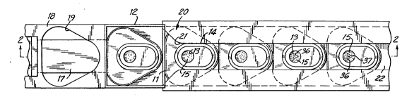
Referring now to the figures, the preferred
system of the present invention has -a stack 10 of
20covers 11 loaded into a magazine 12. Each cover 11
has an aperture 13 and guide means which can
conveniently be guiding wall 14. Secured to the
underside of the cover is a porous support 15.
25The porous support is selected to be compatible
with the reagent to be coated and to have the flow
characteristics desired for the diagnostic procedure
to be performed with the finished device. Suitable
materials for the diagnostic support include
nitrocellulose, nylon, and other membranes well known
to those skilled in designing diagnostic assays. The
porous support can be secured to the cover by any
suitable means. For examp}e, the porous support can
be secured with heat sealing, solvent welding, sonic
welding or an adhesive.
~r~
- 1 331 724
A magazine 12 holds a stack of covers for
delivery to a spring biased holding plate 18. The
holding plate 18 has an aperture 19 therethrough.
The aperture 19 is sized and dimensioned to allow the
bottom-most cover 11 to pass through it when it is
aligned with the cover. Below the holding plate 18
is an indexing arm 17. The clearance between the
indexing arm and the holding plate is sufficient to
hold only one cover.
In operation indexing arm 17 advances to push
covers in a guide channel 20. At the same time
holding plate 18 advances so that aperture 19 is
aligned with the bottom-most cover in the magazine
12. The bottom-most cover falls through the aperture
19 and rests on indexing arm 17. When the indexing
arm and holding plate have completed one stroke they
retract so the cover resting on the indexing arm
falls into the guide channel 20. Retraction of the
holding plate takes the aperture 19 out of alignment
with the covers in the magazine so that none falls
through until the next stroke of the indexing arm and
holding plate~ The action of the indexing arm also
indexes each of the covers 11 loaded in the guide
channel to a next station.
.
The guide channel 20 has a slot 21 through its
upper surface dimensioned to receive the guiding wall
14 of the cover 11. This construction assures
correct orientation of the cover 11 in the guide
channel 20. The guide channel is shown with a lower
slot 22 running its entire length. Those skilled in
the art will appreciate that the lower surface of the
guide channel~could be constructed as a solid table
having holes through which the fluid collection heads
of the coating stations can pass.
lo 1 33 1 72~
The coating stations 30 and 30A have dispensing
assemblies 31 and 31A and fluid collection heads 40
and 40A. The dispensing assemblies have reservoir
cannulas 32 and 32A for delivering reagents to be
coated from their respective reservoirs (not shown)
to dispensing cannulas 33 and 33A which are each in
fluid communication with its respective reservoir
cannula.
The dispensing assembly for station 30 is shown
for coating in a distinct triangle pattern 36. The
pattern is achieved by incorporating a template 35
into the dispensing assembly. The dispensing
- assembly of station 30A is shown for coating a very
15- small dot 37 of a positive control reagent. In this
case a template is not necessary.
The fluid collection head 40 has a vacuum port 41
and a frit 42. The vacuum-port 41 reduces the
pressure below the frit 42 sufficiently to pull a
liquid through the porous support. The frit 42 is
preferably dimensioned to be slightly larger than the
aperture of the cover. This construction assures
that suction applied through the frit pulls through
the entire surface area of the porous support within
the area defined by the aperture. The frit also
serves to support the cover and its porous support
during the coating process. When the porous support
is a relatively fragile membrane (e.g. nitrocell-
ulose) use o a frit having a surface area slightly
larger than that of the aperture is particularlyuseful to avoid damaging the porous support during
coating. This feature is particularly important to
avoid performance problems with the finished
11 1 33 ~ 724
diagnostic device because flow rates across the
porous support are important to efficacy of the
device. The fluid collection head preferably
includes a compressible washer below the frit 42 to
cushion the frit as it contacts the lower surface of
the cover and the porous support. This cushion
allows for variations within a tolerance of the
thickness of the porous support.
The reciprocating means for each coating station
is shown as two pneumatic cylinders 34 and 43 for
coating station 30 and 34A and 43A for coating
station 30A. Cylinders 34 and 34A serve to move the
dispensing cannulas into and out of close proximity
with the porous support. Cylinders 43 and 43A serve
to move the fluid collection head into and out of
contact with the lower surface of the porous support.
Preferably reciprocating cylinder 34, dispensing
cannula 33 and template 35 are formed as a
subassembly which is easily removable from the
coating station assembly. Also preferred is
construction of reciprocating cylinder 34A and
dispensing cannula 33A as a single subassembly.
~hese constructions allow rapid exchange of the
subassemblies so that the ragents, pattern(s) or both
to be coated can be changed when desired.
In use a cover is delivered to the guide channel
as described above. The indexing arm 17 urges the
cover 11 into and along the guide channel 20.
Preferably one stroke of the indexing arm 17 advances
each cover 11 in the guide channel 20 by one
station. When the aperture 13 of a cover reaches
: - , . . ~ . . ~ ~ -
, ~ , : -~ .
t ~
1331724
12
coating station 30 cylinder 43 is extended to support
the cover and its porous support as the dispensing
assembly is lowered by extension of cylinder 34.
Simultaneously with extension of cylinder 43, or
thereafter, cylinder 34 lowers so that the template
contacts the porous support and the dispensing
cannula 33 is in close proximity to the porous
support. When the two reciprocating cylinders 34 and
43 are fully extended the fluid in the reservoir
cannula 32 is allowed to flow into the dispensing
cannula 33 and from there onto the porous support
15. The reduced pressure in the fluid collection
head 40 pulls the fluid through the porous support
leaving the reagent in the fluid secured to the
porous support.
After the reagent has been coated at station 30
the cylinders 34 and 41 retract and the indexing arm
17 pushes the first cover in the guide channel which
in turn causes the other covers in the guide channel
to advance so that the cover just coated at station
30 is pushed to station 30A where another reagent can
be coated. As can readily be appreciated, any number
of coating stations can be combined in a single
system. Also each dispensing assembly can
incorporate any number of dispensing cannulas. Thus
a single reagent can be coated from a plurality of
cannulas or multiple reagents can be coated at the
same station using multiple cannulas. Similarly, the
template can have a single pattern or a plurality of
patterns. The system of the present invention is
particularly useful because it is amenable to so many
variations in coating patterns by simply changing the
dispensing subassembly and configuring the line with
multiple coating stations in series.
_.. , ~ .. . . , . , . . ~ . ... . . . . .