Note: Descriptions are shown in the official language in which they were submitted.
1331~12
: ~ .
Technical Field
The invention relates to the presentation of
:~ 20 various aircraft operating parameters and mission
information to the pilot, via a display system.
-
S Background Art
Modern high-performance aircraft require the
monitoring of a tremendous amount of sensor data
indicative of both airframe and engine operating
parameters simply to remain aloft. Much of the sensor
. . .
,,.
~ ~ .
? ` . :~ ' : '
'.~
` ` - . - ` '"- :- `: ` ' .: : : :. `
3 1 ,'
data is combined and analyzed by various automated
flight systems, such as a Flight Management System, a
Flight~ Director, an Autopilot, a Stability Augmentation
System, and/or an Electronic ~ngine Control System to
control certain operating parameters at preset limits,
to pilot-selected values, or within safety thresholds.
The ultimate effect of these systems is typically
"transparent" to the pilot and pllot workload is
reduced. Nevertheless, it is still vital that many
parameters are presented via a display to the pilot so
that he is cognizant not only of present operating
conditions, but also of available "reserves" within the
flight envelope of the aircraft.
In the context of a military aircraft, a plethora -
of weapons status and flight mission data must also be
presented to the pilot.
One can readily appreciate the need to present
data to the pilot in as succinct, unobtrusive, and
meaningful manner as possible, especially in the
context of a single pilot aircraft.
To this end, it has been known to combine data and
present only the combined result to the pilot in the
form of "symbology", or a pictorial representation, -
rather than in digital or analog scale form. The
latter is exemplified in U. S. Patent No. 4,368,517
(Lovering, 1983).
Besides console mounted displays, heads-up and
helmet-mounted displays are becoming more used for
displayinq data and symbology. Both heads-up and
helmet-mounted displays present information, typically
i
~ .
1 ~3~812
via collimated light rays to the pilot's eye or eyes
via a semi-transparent display so that he can perceive
both the imaged information and the view out of the
cockpit simultaneously without having to lower his head
or accommodate his eyes. U.S. Patent 4,305,057
(Rolston, 1981) illustrates the heads-up type and U. S.
Patent Nos. 3,923,370 (Mostrom, 1975), 4, 269,476
(Gauthier, et al, 1981), and 4,446,480 & 4,439,157
(Breglia, et al, 1984) are exemplary of helmet mounted
display systems.
Despite the advances that have been made in the
area of helmet-mounted display symbology (see for
instance, U. S. Army publication TM 55-1520-238-10,
relating to the Apache Helicopter, at pages 4-19
through 4-23) there still exists a need for improvement
and room for innovation.
Disclosure of the Invention
It is an object of this invention to provide an
improved symbology for use in a display system.
According to a first aspect of the invention, an
image of an altitude symbol (30) is provided to a pilot
by means of a display device (22) in response to a
sensed aItitude signal. The altitude symbol comprises a
larger isosceles triangle (34) and a smaller isosceles
triangle (36) sharing its base with the larger
isosceles triangle. The position of the triangles
within a rectangular area (32) on the display device
, . j.. .. . ....... .. ~.. ... . . .
: - ~ . . - . . . . .
! . ` ~ . . : . .':: `
'`''' ' ` ,~ ~' .`
t -~3 1 8 1 ~
corresponds to the aircraft altitude. Portions of the
triangles which may, according to the altitude, fall
outside of the rectangular area are occluded.
A line and a digital display of altitude may
appear across the rectangular area. Portions of the
triangle in the regions of the line and digital display
are occluded.
This display will allow the pilot to acquire
altitude information more quickly and with less
cognitive processing than is currently required. This
display concept will allow the pilot to readily --
perceive a gross approximation of the aircraft altitude
by merely glancing at this display and seeing how
"high" the aircraft is compared to known height
~5 yardsticks (e.g., triangles) which might instead be
superimposed over the real-world view. The display
provides a better means of information transfer using
only peripheral cueing. The precise altitude is also
provided via the digital display.
The triangle symbols could be designed to display
alternate altitudes, such a 0, 25, 50 and 100 units,
depending on mission suitability.
According to a second aspect of the invention, an
image of a power symbol (50) is provided to a pilot by `
means of a display device (223 in response to at least
two sensed torque signals. The power symbol comprises
a vertical line (56) which serves as a scale, and
arrowheads (58, 60) disposed on either side of the
scale at a position indicative of the engine torque of
two engines. The arrowheads may only be displayed when
there is a threshold torque split between the two
- 4 -
~ s ~
1331~12
engines, or when the torque on any single engine goes
out of range. A digital display of average torque may
be included in a box at the bottom of the scale.
For helicopters, a solid triangle symbol (62) may
be displayed along the scale to indicate power required
to hover out of ground effect.
A horizontal line symbol (64) may be displayed
along the scale to indicate the maximum power available
from the engines altogether.
For helicopters, a thicker vertical line symbol
(66) may be superimposed upon the scale to indicate the
instantaneous estimated power setting as a function of
the pilot's collective stick input. For fixed wing
aircraft, this might indicate a cockpit torque command.
According to a third aspect of the invention,
images of navigational symbols are provided to a pilot
by means of a display device (22) in response to sensed
navigational signals. A horizon line symbol (72) is
provided in such a way that it coincides, from the
perspective of the aircraft or pilot, with the horizon.
A rectangular box symbol (70) is provided above the
horizon line at a position indicative of the location
of the current mission waypoint, and a digital display
(76) of the current waypoint number or the distance
thereto may be presented in the box. A line (74)
extends from the box down across the horizon line to a
point (78) below the horizon line and is suggestive of
the distance of the aircraft from the current waypoint.
The line (74) may be imagéd such that its position on
the horizon corresponds to the bearing to the current
- 5 -
~ . :.. ... :
1 ~ 3 1 ~ 1 2
waypoint from the perspective of the aircraft or pilot.
The point (78) may terminate such that its image
coincides, from the perspective of the aircraft or
pilot, with the actual location of the waypoint on the
earth. Another symbol (80), indicative of the position
of a subsequent mission waypoint may also be presented.
A symbol (84) may be provided at a position
relative to the current waypoint symbol (70) indicative
of the direction which the pilot may steer to return
via a smooth path to the mission leg which will take
him to the current waypoint.
This display will allow the pilot to acquire
flight plan (navigational) information as well as
heading/steering command cues more quickly and with
less cognitive processing than is currently required.
This display concept will allow the pilot to readily
perceive the location of the waypoints due to their
superimposition over the real-world view providing a -~ -
better means of information transfer. - ~--
2~ ~n accordance with a fourth aspect of the
invention, an image of an azimuth tape symbol (90) may
be provided indicative of the real world azimuth of the
pilot's view out of the cockpit.
An image of another symbol (112~ may be presented,
in accord with a fifth aspect of the invention, in
response to sensed signals indicative of the position
of the pilot's head with respect to the cockpit, the
~symbol (112) being indicative of cockpit structures so
that the pilot is cognizant of his orientation within
- 6 -
~,''' ,`: '' ~, ' .
. ~ ~ .....
-
1331~12
the cockpit under night flying conditions in which
imagery from image sensors~is also provided to the
pilot.
According to a sixth aspect of the present
invention, in response to sensed siqnals indicative of
aircraft heading, velocity and acceleration, a symbol
(120) may be presented to provide horizontal velocity
information to the pilot. A velocity vector symbol
takes the form of a line emanating from a circular
symbol and has a length magnitude proportional to the
magnitude of the sensed velocity. The direction of the
vector relative to the vertical axis of the display
indicates the direction of the vehicle velocity
relative to its longitudinal axis. The acceleration of
the aircraft is indicated grossly by the rate of change
of the velocity vector itself. However, it is also
indicated by the form of an arrowhead at the other end
of the velocity vector. As the rate of change of
velocity increases the arrowhead points away from the
central circular symbol. Diminishing velocity is
indicated by the opposite direction of the arrowhead.
A constant velocity is indicated by a flat acceleration
cue (making the velocity vector arrowhead appear as a
"T"). A box can be provided around the central
circular symbol in order to quantitatively indicate a
selected number of knots from which the magnitude of
velocity can be estimated. A decision may be made to
only indicate the box when the velocity is less than a
selected number of knots, e.g., 10 knots so that it
1331~12
does not become a distraction while traveling at
greater rates of speed where an exact magnitude is
of no concern.
In accordance with a particular embodiment
S of the invention there is provided a helmet mounted .
display system for displaying images to a pilot in
an aircraft cockpit, comprising:
sensor means, responsive to the attitude
of the helmet with respect to a cockpit coordinate
system, for providing a helmet attitude signal
indicative thereof;
signal processing means, responsive to
said helmet attitude signal for retrieving stored
signals indicative of points within the cockpit
coordinate system which are within the field of view
of the pilot as indicated by said helmet attitude -~
signal, said signal processing means also responsive
to said helmet attitude signal, for converting said
retrieved signals from said cockpit coordinate
system to a helmet coordinate system and from said
helmet coordinate system to a display coordinate
system and for providing converted retrieved signals
for display; and
means for providing to the pilot, in
response to said converted retrieved signals,
symbolic images of said cockpit points such that
said symbolic images coincide, from said pilot's
point of view, with said cockpit points.
From a different aspect, and in accordance
with a particular embodiment of the invention there
is provided a helmet related display method for
) providing symbolic images to a pilot in a cockpit,
comprising the steps of:
sensing the attitude of the helmet with
respect to a cockpit coordinate system and providing
a helmet attitude signal indicative thereof;
-- 8 --
~ .,
- 1331~12
retrieving, in response to said helmet
attitude signal, a plurality of stored cockpit
signals indicative of points within a cockpit
coordinate system which are within the field of view
of the pilot;
converting, in response to said helmet
attitude signal, said plurality of cockpit signals
into a corresponding plurality of helmet signals
indicative of said points in a helmet coordinate
system;
providing, in response to said helmet
signals, a corresponding plurality of display
signals indicative of said points in a helmet
display coordinate system; and
providinq, in response to said display
signals, one or more symbolic images of one or more
corresponding points in the cockpit which are within
the pilot's field of view, said symbolic images
being provided so as to coincide, from the point of
view of the pilot, to the actual positions in the
cockpit of said points, regardless of the helmet's
attitude with respect to the aircraft.
These and other obiects, features and
advantages of the present invention will become more
apparent in light of the following detailed
description of a best mode embodiment thereof, as
illustrated in the accompanying drawing.
Brief Description of the Drawing
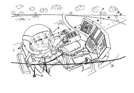
Fig. 1 is a block diagram of an aircraft
diæplay system;
Fig. 2 is a pictorial representation of
altitude display symbology, according to the first
aspect of this invention;
Fig. 3 is a pictorial representation of
35 power display symbology, according to the second ~ ~
aspect of this lnvention; - ~-
- 8a - ~
: . '
1331812
..
Fig. 4 is a pictorial representation of
waypoint and steering cue display symbology,
according to the third aspect of this invention;
Fig. 5 is a pictorial representation of
heading display symbology, according to the fourth
aspect of this invention;
Fig. 6 is a pictorial representation of
cockpit structure display symbology, according to
the fifth aspect of this invention;
Fig. 7 is a pictorial representation of
the displays of Figs. 2-5 as they might
(aggregately) appear to a pilot using a display
system of' the helmet mounted type;
- 8b -
133~2
Fig. 8 is an illustration of angular relations
between a flight plan leg and an aircraft off-course;
Fig. 9 is an illustration of several paths flown
by an off-course aircraft from various positions back
on-course, according to the present invention;
Fig. 10 is an illustration of a prior art
velocity/acceleration symbol;
Figs. llA-llC illustrates a velocity/acceleration
symbol, according to the present invention; and
Fig. 12 illustrates a velocity/acceleration
symbol, according to the present invention for three
cases of acceleration.
Best Mode for Carrying Out the Invention
Fig. 1 shows an aircraft computer 10 receiving
signals from various airframe sensors 12 (such as
position, heading, attitude, and altitude), engine
sensors 14 (such as torque), control sensors 16 (such
as cyclic/collective pitch and yaw), helmet attitude
and position sensors 18, and input devices 20 (such as
devices for entering flight plan information). In a
manner that is generally within the scope of one of
ordinary skill in the art, the computer 10 generates
output signals that appear as digital data, analog
data, and/or symbology for providing images thereof to
the pilot on a display system (22) such as, without
limitation, a heads-up display or a helmet mounted
display. Figs. 2-7 are illustrative of various
symbolic images as they may appear to a pilot on a
display, according to the present invention.
_ 9 -
-~ : ~;.
1331~12
ALTITUDE SYMBOLS
Fig. 2 shows four examples of an altitude symbol
for display as symbolic altitude images in response to
sensing four discrete altitudes by means of, e.g., a
radar altimeter (sensor 12 of Fig. 1). The four
examples are labeled 30A, 30B, 30C and 30D and are
herein generally referred to by the numeral 30.
The altitude display 30 is presented within a
discrete rectangular area 32 (shown in phantom) of
height h and width w on the viewing screen of a display
system such as a heads-up or a helmet-mounted display
system type. With reference to the example 30C, two
isosceles triangles, a larger triangle 34 and a smaller
triangle 36 are presented within the area 32. The
larger triangle 34 has a height h and a base width w,
and shares its base (which may or may not actually be - --
visible on the display) with the smaller triangle 36
which has a height h/2 and a base width of w. A fixed
location line 38 appears horizontally (in all
instances) across the area 32 at h/2, or at the apex of
the smaller triangle 36 as shown in the example 30C. A
digital display 40 of altitude appears just above the
line 38.
The two triangles 34 and 36 move, in unison, up
and down within the area 32 in response to altitude
changes and, as may be readily noted in the examples
30A, 30B and 30D, the portions of the triangles 34, 36
outside of the viewing area 32 are occluded (made not
visible to the pilot). Thus, we see in the examples
-- 10 --
~ ,: :,
-~
~ 1331~12
3OA, 3OB, 30C and 3OD the altitude symbology as it
would appear to the pilot at four discrete
altitudes, zero, fifty, one hundred and two hundred
units, respectively. It will also be noted that the
triangle symbols 34, 36 are occluded in the region
of the digital display 40.
The triangles 34, 36 will move vertically
downward as the aircraft altitude increases, and
upwards as the aircraft altitude decreases. The
fixed location digital display 40, which serves as
the zero reference, will remain at a fixed height on
- the screen. Therefore, the pictorial display will
appear to slide behind the digital display.
POWER SYMBOL
15Fig. 3 shows the display associated with
engine torque and, for helicopters, power available
to hover. Engine torque for one or more engines may
be a directly measured parameter (sensor 14 of Fig.
1), and power available to hover is typically a
calculated value based on several engine operating
parameters. See for example, U.S. Patent 4,467,640
(to Morrison, 1984) and Canadian Patent 1,206,261,
Lappos et al.
The display format utilizes a pictorial
25 display 50 showing various aircraft parameters. The -
display 50 is essentially a "thermometer". The data
supporting these displays are derived from signals
provided by aircraft sensors, which signals are --
filtered and processed to
- 1 1 -
:',`' ~ . .
- `
1331~12
produce integrated power indications: engine torque
(both digital and analog), power required to hover out
of ground effect, and power available (power margin).
The thermometeF has a rectangular base portion 52
containing a digital display 54 of the average torque
produced by the engines as a percentage of rated
torque. A vertical line symbol 56 rises up from the
base portion 52 and is "fixed" in that it serves as a
scale for other "moving" symbols. The top of the scale
corresponds to 120% (maximum) of rated (100%) torque.
The bottom of the scale corresponds to minimum (0%) ~ -
engine torque.
Two opposing "arrowheads" 58 and 60 may be
disposed one on either side of the scale 56 to
represent the instantaneous torque of each engine (one
arrowhead per engine) in an analog manner by their
position along the scale. This gives a ready
indication of torque "split" to the pilot, but to avoid
displaying unnecessary information, the arrowheads need
only be displayed whenever the difference in torque
between the two engines exceeds a selected level, such
as 15% or when the torque on any single engine goes out
of a chosen range.
- For helicopters, a right triangle symbol 62 is
positioned on the scale, as shown, to represent the
minimum power required to hover out of ground effect.
This is a computed parameter, and the visual indication
thereof is quite important to the pilot vis-a-vis the
estimated power available symbol described below. As
will be readily appreclated by one of ordinary skill in
- 12 -
.: . - :
- :
.. : :
1 33 1 ~ 1 2
the art, if the power required exceeds the estimated
power available, in other words if the triangle symbol
rises above the estimated power available symbol
described below, severe degradation of aircraft
performance may occur.
The estimated power available symbol 64 is a
horizontal line which presents an estimate of the
maximum power available from both engines taken
together, given current atmospheric conditions. This
horizontal line intersects the torque scale 56,
typically near the top thereof.
A solid line 66, thicker than the line 56, (i.e.,
the "fluid" of the "thermometer") rises upward along
the line 56 from the base portion 52. This symbol 66
is an analog representation of the instantaneous
estimated power setting, which is a computed parameter,
and represents the power setting commanded by the -
pilot's collective input. ; -- -
The torque scale 56 and the frame 52 around the -~
digital display 54 are the only elements of the power
display 50 that remain static. All of the other
display elements move dynamically with a range of o%
and 120% of torque.
This display will offer the pilot a better, more -
extensive combination of pre-processed information than
is currently available. For example, as long as the
display shows that the power required to hover out of
ground effect triangle is below the estimated power
available line, the pilot will known that the aircraft
is fully capable of performing any desired maneuver due
- 13 -
. - :
~: .
~:
~331~12
to the fact that the hover out of ground effect
maneuver is the most power intensive flight maneuver.
In addition, the instantaneous estimated power setting
display element will effectively anticipate the
mechanical delay between a collective input and the
actual torque change in the engines, thereby
counter-balancing the loss of the proprioceptive
feedback incurred due to the utilization of a modern
side-arm controller.
WAYPOINT SYMBOLOGY
Fig. 4 shows symbols indicative of "waypoints"
superimposed on a horizon line. The waypoints
represent one or more ground position points in a
series of such points which make up benchmarks in a
preselected flight plan. The earth coordinates of the
flight plan waypoints would typically be entered prior
to takeoff into the computer lO of Fig. 1 via one or
more of the input devices 20.
The display format may utilize a pictorial ''~
representation of two such navigational cues on a
horizon line, showing both the upcoming and subsequent
waypoints with respect to each other and the horizon.
The horizon line may be displayed such that it remains
parallel to the horizon and in-line with the horizon,
from the perspective of the aircraft or the pilot.
The large rectangular flag 70 represents the
upcoming (current) waypoint along the programmed flight
plan. The vertical height of the flag 70 relative to
- 14 -
':
,. i :
~ .
'-'.:~ :' . :
,
~ ', '
. ~- - ~ .
1 3 3 ~
the displayed horizon line 72 does not change, but the
stem 74 "grows" as the waypoint gets closer and
appears, from the perspective of the aircraft or the
pilot, as if it were actually attached to the point it
represents on the earth. The bottom of the stem 74
will has a small solid symbol 78 attached to it which
remains "planted" on the same earth point. The flag
has a digital display 76 which may be the waypoint's
identifier or an indication of the distance to that
point. The stem of the flag will always remain
perpendicular to the horizon line. Changes in attitude
of the referent aircraft or helmet will result in the
horizon along with the flagpoles "tilting," i.e., the
horizon symbol always stays with the actual horizon and
the flagpoles always remain upright with respect to the
horizon. ~ -
The smaller square flag 80 depicts the location of
the subsequent (next) waypoint in the flight plan.
Unlike the larger flag, the stem of the small flag does
not grow beneath the horizon line 72. The stem 82 of
the flag 72 always remains perpendicular to the horizon
line. There may be, but there is preferably no digital
display in the smaller flag 80.
As suggested above, the horizon and both of the i-~
waypoint symbols 70, 80 will move in various directions
on the image source or display 22 surface (e.g., a CRT)
proportional to the relative attitude of the aircraft
alone (for heads-up displays), or the aircraft and--i~
pilot's helmet taken together (for helmet-mounted
- 15 - -
1331~1~
displays). The flags will therefore appear to the
pilot to have been "planted" at a specific
geographical location in the real-world.
In order to properly position the horizon
and waypoint symbology with respect to the pilot's
helmet, for a helmet-mounted display, it is
necessary to conceive of the earth, the aircraft and
the pilot's helmet as being associated with separate
coordinate systems having separate origins freely
translating and rotating with respect to one
another. On the other hand, if it is only desired
to position the horizon and waypoint symbology with
respect to the aircraft, it is only necessary to
conceive of the earth and aircraft as being -
associated with separate coordinate systems. The
pilot is considered part of the aircraft for that
case (the simple heads-up display case), i.e., his ~ -
helmet position and attitude are ignored and assumed ;~;
to be in a fixed position and orientation. See U.S.
Patent 4,305,057 to Rolston.
Such equations can be used for the simple
heads-up display case where the aircraft is the
referent for imaging purposes. For the head-mounted
display case, where the pilot's head is the
referent, it is necessary to perform an additional
set of translations and rotations. See Canadian
Application Ser. No. 590,980 for an example of a
series of coordinate transformations (from earth to
aircraft to helmet to display coordinates).
30The manner in which the waypoints are
retrieved may be thought of as progressing from
retrieving a first waypoint position signal and
identifying that signal as the current waypoint
- 16 -
,__,_ _ _ . . - - - - . - - -
~`".',i' ' ' -`
, ~-'. : '~' . '
''` .'' :,, ' ' ': ' ' : ' ' ~
~ 1331~12
position signal until it passed. At the same time
as the first waypoint position signal is retrieved,
a second waypoint position signal (next in sequence)
is retrieved and identified as the subsequent
waypoint position signal indicative of the position
of the next waypoint in the selected flight plan
after the upcoming or current waypoint.
After determining that the aircraft is
within a first selected distance of the current
waypoint, a determination is made as to whether the
aircraft or helmet has an increasing distance
between itself and the upcoming waypoint; if so, a
further determination is then made as to whether or
not the d.istance between the aircraft or helmet and
the subsequent waypoint position is decreasing. If
so, the subsequent waypoint is from that point on -~;
identified as the current waypoint and a third
waypoint position signal is retrieved from storage
and identified as the new subsequent waypoint
position signal. If the aircraft comes within a
second selected distance of the current waypoint
(less than the first selected distance) before it is
determined that both the distance to the current
waypoint is increasing and the distance to the next
2S waypoint is decreasing, the identity of the current
waypoint is at that point automatically changed to
that of the next waypoint. The same process is
continued until the destination is reached. Such a -
procedure is described in more detail in copending ~ -
Canadian Application Ser. No. 590,980. ~
: , ''''
1331&12
STEERING CUE SYMBOL
Fig. 4 also shows a steering cue display 84 which
operates in conjunction with the waypoint display.
The purpose of the waypoint flags 70, 80 is to
indicate to a pilot the real world location of the
current waypoint (the one being flown to) and the next
waypoint. These flags occupy their real world
positions with respect to the horizon line both in
azimuth and distance from the aircraft. The distance
from ths aircraft is indicated by the waypoint flag ',.,,:
pole growing larger as the aircraft approaches the
waypoint.
The purpose of the steering cue 84 is to aid the
pilot in reaching the current waypoint. If the
aircraft's position is off the flight leg (the straight
l-ine connecting the last and current waypoints), the
steering cue directs the pilot to return to the flight
leg in a gradual and smooth manner (not to fly directly
at the waypoint). An algorithm and corresponding
illustrative example are disclosed so as to enable one
~ of ordinary skill in the art to implement the steering -
`~ cue display via appropriate software in the computer 10
of Fig. 1.
Thus, the image of the steering cue may be
provided to the pilot in order to indicate an aircraft
heading consistent with following the preselected
flight plan to the current waypoint or, in some cases,
the next waypoint. The steering cue may be presented
in close proximity to and with respect to the horizon
- 18 -
, .,
!
. - . ' ' ' ' ~ . . . '
.: .. ' '' . ' ' " .. : ~ . " , ' ': '.
1331~1~
as shown by symbol 84 in Fig. 4 or a helmet compass
bearing symbol as shown by a symbol 84b in Fig. 5. (As
shown in Figs. 4 & 5, the steering cue may take the
form of a carat-shaped symbol which moves horizontally
just below a compass heading symbol which the pilot may
follow). In either event, the carat symbol may, for
example, also have 3 possible orientations: if the
direction-to-steer is within plus or minus a selected
number of degrees (e.g., 19 degrees) of the vertical --
centerline of the pilot's field of view, then the carat
points upward, as shown in Figs. 4 & 5; if the
direction-to-steer is beyond plus or minus the selected
range then the carat will rotate to either point left ~ ~
or right to cue the pilot which way to turn to bring ~ -
the carat within the selected range.
The steering cue may be provided so as to guide
the pilot back on the current flight leg as disclosed
above or, upon closely approaching a current waypoint
where the next flight leg will shortly be in a
different direction, to guide the pilot so as to enable
him to turn the "corner" in a smooth manner. An
aircraft symbol 84a may be provided as shown in Fig. 4 ~-
in conjunction with the steering cue symbol 84 to
indicate the current heading of the aircraft with
respect to the horizon or, as shown by a symbol 84c in -~
Fig. 5, the helmet compass bearing symbol.
The algorithm first determines, as described abo~e
in connection with the separate description of the
-- 19 --
`.' ~ . ''' .: ' :
.
1331~12
waypoint symbology, when the aircraft has "passed" the
current waypoint and the waypoints (past, current, and
next) are updated.
Referring first to Fig. 8, a point 85a corresponds
to the position on the ground of a current waypoint and
a point 8Sb represents the last waypoint. A point 86
corresponds to the present position of the aircraft.
An angle A measures the angle between a flight plan
path 87 and a line 88 from the current aircraft
position to the current waypoint. An angle B is
indicative of the angle between the path 87 and a line
89 projected from point 86 in the direction to be
indicated by the steering cue, intersecting line 87 at
a point 90.
The algorithm is to set angle B equal to the
arctan of a constant times tanA. The constant will
most advantageously be set to a value between 1.5 and
3.
For cases where the aircraft is closely
approaching the current waypoint, it will be desirable
to change the identity of the current waypoint, for
purposes of the steering cue only, so that an efficient
"corner" may be turned. In other words, the current
waypoint continues to be imaged until its identity is
changed in the normal way, described previously. Some
typical cornering paths to the next waypoint for a plan
- having a right angle turn using this algorithm are
shown in Fig. 9. A circle 91 indicates a selected
distance for changing the identity, for steering cue
purposes only, of a current waypoint 92 to that of the
last waypoint and that of a next waypoint 93 to that of
- 20 -
"` ' `" '`'' ' " . -'' ' '
~ ~331~12
the current waypoint. Fig. 9 also illustrates a
waypoint 93 which preceded waypoint 92 in the flight
plan. Starting with an aircraft position 94 on a
preplanned flight path 94a between points 93 and 92,
the aircraft will trigger a change, for steering cue ~-
purposes only, in the identity of the current waypoint
from point 92 to point 93 once it is within radius 91.
At that time it is now off of the preplanned flight
plan along a path 95. The algorithm will cause the
steering cue B4 to smoothly steer the pilot back onto
the path 95 along a path 95a shown with a heavy line.
Two other examples show starting positions 96, 97
resulting in flights along paths 98, 99, respectively,
onto the new flight path 95. It will be noted in all
cases that the crossover of the circle 91 causes a
change in course due to the change in identity of the
next waypoint.
Aside from cornering, the purpose of the steering ~
cue symbol is to direct the pilot back to the straight ~-
line path ("leg") between two successive waypoints (the
previous waypoint and the current waypoint) when he has
deviated therefrom. This will always place the pilot
back on the prescribed leg of his mission in a smooth
manner.
Fig. 4B is a stylized illustration of a pilot's
line of sight 85 to the horizon symbol 72 of Fig. 4A.
It also illustrates the pilot's line of sight 85a to
the base 78 of symbolic waypoint image 70, 74, 76. A
rise in an undulating earth 85c is shown in section ;;
with the waypoint base 78 coincident with a point
- 21 -
--` 1331~12
thereon, which may be a waypoint such as point 108
in an earth coordinate system illustrated in Fig. 8
of copending application Ser. No. 590,980.
Similarly, Fig. 4C stylistically illustrates the
same scene from the pilot's point-of-view, as
presented by the display with the horizon symbol 72
and waypoint symbol 70, 74, 78 shown.
HEADING SYMBOLOGY
Fig. 5 shows a display combining both
aircraft heading/track angles (sensor 12 of Fig. 1)
and off-aircraft axis targeting/sighting information
such as helmet pointing angle (sensor 18 of Fig. 1).
The heading tape symbol 90 consists of a
full 360 degree circle in a horizontal plane such
that as the pilot turns his head he sees the portion
of the heading tape that corresponds to his line of
3ight. In the example of Fig. 5, the display shows
160 degrees (16) to 190 degrees (19). The symbol
tape 90 may be set up so as to remain fixed in terms
of its screen location so that it always remains
parallel to the upper edge of the displayed area.
- As shown in Fig. 7, for example, the pilot has his
head turned to his right tilted upwardly such that
the tape symbology within his field of view (shown
with solid symbols) appears in the upper portion of
his field of view no matter which way he turns his
head. Thus, the tape symbology "sticks" with the
pilot's head. This is suggested by a non-displayed
portion of a circular tape shown in nonsolid symbols
- 22 -
7r..~
~ 1331812
(in front) and phantom symbols (to the rear) encircling
the pilot's head and which more clearly suggests the
tilted orientation of the tape symbology with respect
to the horizon symbology. It has a one-to-one
correlation with the real-world direction in that a ~-
change in either aircraft or helmet heading corresponds
to an equivalent change in the displayed portion of the ~-
heading tape. It should be realized, however, that the
tape symbology could be presented in-line or parallel
with the horizon at all times.
The display consists of tick marks 92 every 10 ~;
degrees with numerical indicators 94 replacing the tick -
marks at every heading divisible by 10. These
numerical indicators are 2-digit numbers showing the
left-most digits (heading 030 is displayed as 03). The -
Cardinal headings may be replaced by their
representative letter 96 (N, S, E and W) as shown in
Fig. 5, or may be shown in the same way as all other
- directions (see Fig. 7). The heading tape symbol 9o is
augmented by a digital display 98 showing the current
aircraft heading. In this example, the pilot is
looking almost due south (175 degrees), and the
aircraft is flying almost due west (265 degrees).
The entire moving scale rotates horizontally in an
opposite direction but at an equivalent rate as any
change in aircraft or pilot-helmet heading. The
portion of the scale not being displayed is held in
memory until the pilot moves his head as suggested by
the nonsolid and phantom symbols shown out of the
pilot's field of view in Fig. 7.
- 1331~12
The aircraft symbol 84c indicates the aircraft's
current heading with respect to the heading tape and
may be used in conjunction with the steering cue 84b,
e.g., to get back on a leg of a flight plan.
This display allows the pilot to acquire
earth-plane angular information more quickly and with
less cognitive processing than is currently required.
HELMET POINTING ANGLE SYMBOLOGY
Fig. 6 shows a helmet pointing angle display
symbolic image which may be used as a helmet pointing
angle reference to the pilot, for example, while using
night vision goggles or any targeting/sighting system
that is directed by a helmet tracking system such as a
forward-looking infrared (FLIR) imaging system. This
type of display differs from the Heading Display, in
that it provides the pilot with a cue as to where he is
facing within the cockpit itself rather than outside of
the cockpit, but the two types of display techniques
work well together. The Helmet Pointing Angle Display
provides the pilot with a nearly reflexive cue as to
where he is looking within the cockpit during nighttime
operations without the need for cognition on his part.
The display provides, e.g., a pictorial display
110 depicting a cockpit structure (window frames and
instrument consoles) as it would be seen from the
pilot's eye-reference point. These are depicted as the
- 24 -
t' ' ~ ', . ,. ., , ,,'~' ` ,, ~' , ` " , ,
' ' , '.' ' '~i~ .... '
.: ~'' i' ~ ';'' ' ' '
.i~, .. `' `. ' ., " ." ': ' . ~ . : '
~- 1331~1~
heavy lines 112. Only that portion of the display
representing the cockpit structure which is within the
pilot's field-of-view is presented.
The display reference symbology will always
overlay its real-world cockpit structure counterpart.
This display will allow the pilot to acquire, -
under night or low visibility conditions,
targeting/sighting information more quickly and with
less cognitive processing than is currently required.
This display concept will allow the pilot to readily
perceive the current line of sight (helmet pointing
angle) because of the increase in information transfer
and relevance.
This display technique may also be used for other
symbolic images which may also be presented in fixed
relation to the cockpit or aircraft, regardless of the
position and attitude of the helmet with respect to the
cockpit, but which, for example, may not necessarily
- have any direct relation to physical objects or -
structures in the cockpit.
OVERALL DISPL~Y
Fig. 7 shows the altitude display of Fig. 2, the
power display of Fig. 3, the waypoint and steering cue
displays of Fig. 4, and the heading display of Fig. 5,
as they would (aggregately) appear to a pilot on the
eyepiece of a helmet mounted display system. Not shown
, 'is the helmet pointing angle display of Fig. 6 or the
velocity/acceleration symbol of Fig. 12.
~-, . .. .
- 25 - -
. ~' i ~ e . .
.. ' .. , . '` ' ' . '. ''' , '.: ,.: : , ",' ' ' ' . . . . , "
... , ., , ,, ""~,,, , , " ~, ,,,,,,, ,, , ,, ,,,,, ,, , ~ , . . .
-: :
- 1~31~12
It should be understood that other symbols could
be substituted for the various symbols described
without detracting from the cognitive efficiency of the
display symbology herein. In addition, other symbolic
imagery can be provided as well.
VELOCITY/ACCELERATION SYMBOL
Most aircraft do not provide a cue for horizontal
velocity information to a pilot when operating at low
speed and the pilot must interpret the visual scene to
estimate the direction, magnitude, and rate of change
of magnitude (acceleration or deceleration~ of the
vehicle's velocity. One helmet-mounted display and
several panel mounted display techniques incorporate a
velocity vector (denoted generally by a numeral 114)
such as is illustrated in Fig. 10 which emanates from
the center of the display at a point 115. It includes
an acceleration dot (denoted generally by a numeral
116) which is used to indicate the direction and
magnitude of horizontal acceleration by its position
relative to the center of the display. An arrowhead
(denoted generally by a numeral 117) is attached to the
end of the velocity vector 114. Thus, for Fig. 10(A),
a positive acceleration is indicated by a point 116a in
the direction of a velocity vector 114a. For Fig.
lO(B), the acceleration is zero and a velocity vector
114b is indicating a constant velocity. In that case,
a dot 116b coincides with an arrowhead 117b which is
used at the end of the velocity vector.
- 26 -
S~ ` `i -, - ", " ~, ", , , ",
~ . " ' . , .
,, ' ` ' , ' ''- ~ ', ''' ' ' ' ' ;,' ' ' ' : ~
~'~'' ' ': " .'`'" : - , , ~ . :
,,:, . - ~
~`' :`-''' "'' ' " , : ,, ' '' : ''. :
i. ' ' ' ~ ~::, :
1:7~31~12
.. ,
With this information, according to the prior art,
the pilot determines the control inputs required to
achieve the desired velocity state. A stationary hover
task requires the pilot to cancel any velocity, and the
precision of the hover point is determined by the
pilot's ability to recognize and correct velocity
changes quickly and accurately.
The pilot's ability to interpret visual data from
outside the cockpit is dependent on many factors
including external cockpit visibility, surface
conditions, level of ambient brightness (day, night,
dusk) and existence of obscurants are some examples.
Rotorwash during landing and hover in remote areas
often causes heavy obscurants (dust, snow) to
visibility. Some missions may call for flight in poor
visibility conditions. When the visual scene cannot be
interpreted, the pilot must rely on artificial cues or
lose control of the aircraft. The prior art symbology
- is helpful but not completely informative because of
~- 20 the lack of quantitative information and the absence of
a`correlation between the velocity vector and the
acceleration cue.
Referring now to Figs. llA-llC, the length of a ~
velocity vector (denoted generally by a numeral 120 -
with various suffixes) changes proportionally to the
magnitude of the velocity of the aircraft. The
direction of the vector relative to the vertical axis
of the display indicates the direction of the vehicle ~ -
velocity relative to its longitudinal axis. The
acceleration or deceleration of the aircraft, i.e., the
- .: --::~ -
-
- 27 -
:
~ 1331~12
rate of change of the velocity vector may be perceived
in a gross fashion by observing changes in the
magnitude of the velocity vector. However, this
requires the pilot to view the symbol for a relatively
long period of time. Therefore, for instant cognition,
velocity rate of change may also be indicated by a
acceleration arrowhead with special features, according
to the present invention. When the velocity is
increasing, as shown in Fig. llA(A) an arrowhead 122
points away from a point 115a. Diminishing velocity is
indicated in Figs. llA(C) by an arrowhead 126 pointing
toward point 115a. A constant velocity is indicated in
Fig. llA(B) by a flat acceleration cue making a
velocity vector arrowhead 124 appear as a "T".
The magnitudes of the velocity vectors 120a, 120b,
120c of Figs. llA(A), (B) and (C) all have about the
same magnitude, being greater than a selected
magnitude, such as 10 knots.
Referring now to Fig. llB, again, three different
velocity rates of change are shown in Figs. llB(A'),
ll(B') and ll(C'). All three cases have approximately
the same magnitude velocity vectors 120a' which is less
than the selected value of 10 knots. Upon reaching a
velocity less than the selected velocity of 10 knots, a
symbol 130 having dashed lines appears surrounding the
point 115. Although illustrated as a box, the symbol
may also be a circle, or some other convenient shape
and indicates, approximately, a velocity of, for
example, 5 knots. Thus, if the magnitude of the
velocity vector 120a' is reduced in size so as to
- 28 -
,~,,, . . . - ;,-- -.: - .. .
P.- .':`- .-'-. .. '', . .:,'- :`
:'` '' ': :: ': ` '
.. . ;' .
`; . ~. :, :' . ' : -
, ::` `:: ` ,~'': ' ~ ` " '. `
,` ~ ; ` . , ~` . . ~ ' :
~i'`' ". ' '' :' :`'~ : . .` '` :`
`,'~`'`: . " . : ~., . : ' ' ` :
.' ~ , . ` ` ' ` ` : `
1:~31~312
coincide with the edges of the box 130a then the pilot
will know that the aircraft is traveling at about 5
knots. Velocity vectors slightly longer or shorter
than the boundaries of the symbol 130 can be easily
mentally estimated by the pilot in magnitude in analog
fashion.
It will be observed that the velocity symbols
120a', 120b', and 120c' of Figs. llB(A'), (B'), and
(C'), respectively, are all tilted to the left,
indicating to the pilot that the horizontal component
of the aircraft's velocity is off to the left of the
longitudinal axis of the aircraft.
Figs. llC(A "), llC(B''), and llC(C'') are similar
to Figs. llB(A'), llB(B'), and llB(C') in that the
velocity vectors are pointing in the same direction for
the same three types of rates of change (i.e.,
acceleration, constant velocity and deceleration,
respectively). However, the magnitude of velocity
vectors 120a ", 120b " , 120c " has become, relatively
speaking, very small. In fact, they are lesser in
magnitude than another selected value, e.g., S knots,
at which point the dashed lines 130 become solid lines
132a, 132b, 132c. This technique may be used thusly to
indicate that a hover hold system has become active at -
less than, e.g., the selected value of 5 knots.
Fig. 12 illustrates how the arrowhead 122 may be ~-
altered for different magnitudes of acceleration in a
more-or-less continuous manner. For example, Fig. -
12(1) shows the arrowhead 122a at an acceleration value
a1 which is greater than an acceleration value a2 shown
- 29 -
~ - , ... . . .
,, ,. . - .. -, . . . . , ~.................. ~ i .
~. - - - , . . -.
1331~1~
in Fig. 12(2). It will be noted that the arrowhead
122a assumes an extreme acute angle while the arrowhead
122b of Fig. 12(2) forms almost a right angle.
Similarly, for Fig. 12(3) the arrowhead 122c forms an
obtuse angle where acceleration value a2 is greater
than acceleration value a3. Thus, as the rate of
change of velocity increases, the angle of the
acceleration cue "ears" or "wings" get more acute. The
same principle may be used for decelerations with the
degree of acuteness also indicating high absolute
values of rate of change and with the degree of
obtuseness indicating low absolute values of rate of
change in velocity.
Since the cue is generated by sensor data and may
always be presented on the display, it never degrades
in operational conditions and interpretation of speed
and acceleration are much improved over previous
systems. Of course, the values applied to trigger the
scale boxes could be changed according to mission ~
requirements. For example, a mine sweeping tow mission
that requires constant velocity could have a two
rectangular boxes inside one another indicating
velocity tolerances.
Although the invention has been shown and
described with respect to a best mode embodiment
thereof, it should be understood by those skilled in
the art that the foregoing and various other changes,
omissions, and additions in the form and detail thereof
maybe made therein without departing from the spirit
and scope of the invention.
- 30 -
!`~.` - ~ - . - . :. - . - ~ :
:`.- :` ' ' : : . ..
': ' . .: .
, :; . -` ' - ' : . : :
: ~ , :. , :
- - :; : :. - . :::` :' :
.`-: -' . : , ,.. .. `.- . :
.' ~........ ....... ,.,... . :
s~ , ` ,. . , , - :
,` -: : . ' . :. ' ~.- ' - .
. ~ . . . . .