Note: Descriptions are shown in the official language in which they were submitted.
1331871
This application is a divi6ional application of
copending application 569,825, filed June 17, 1988 ~ `
The present invention relates to a portable air blower,
particularly an electric blower, and to such a blower which
ay be installed on the collecting tank o~ and also ~ay sorve
as the blow ~otor of a vacuu~ cleaner, i~ desired
A portable blower has a blower housing with an iDpeller
or fan in it that draws air into the housing and blows it
through a directed outlet fro~ the housing one ~uch blower
i~ hown in U S Patent 4,325,163 Since the blower housing
ha~ an inl-t, and suction nQcQssarily devolops at the inlet,
th blover ay bo used to draw a vacuu~, a8 with a vacuu~
lS cl un r, and ay additionally b installed on th collecting
tunk o~ a vacuun cleaner for generating the needed vacuur
Portabiliti, light weight ~nd siuplicity-~re all
d sirable attributes of a portable blower
Furt~ r, th blower ay rest aqainst or be seat d upon a
surface, and one or the other of its ends ~ay contact the
surfae- or contact the body or the clothing of a person using
it The intakes into the blower should not beco~e blocked or
- 1331871
clogged through contacting the surfaces or the body or
clothing of the user. Further, there ~ust be security
against a user accidentally inserting hi~ fingers and against
other objects entering the blower. Various grills are known
for thi~ purpose. Finally, if the blower is installed on a
support, such a~ the tank of a vacuu~ cleaner, or the like,
ea~y attach ent and detach~ent of the blower the support is
desirable and also ready ad~ustment of its orientations is
desired.
The present invention provides an i~proved blower:
which protects the user against inadvertently inserting any
ob~ect~ into the blower; which prevent~ any ~urface or
~atorial6 against which the blower i6 rested from blocking
entrance of air into the blower; which enables easy
attachnent of the blower to and re~oval of it from a support,
such a8 a tank: which ~eparates the uain airflow pathway
through the blower fro- another airflow pathway pa~t the
uotor which operates the blower; and which enables easy
reorientation of the direction of the blower with respect to
the ~urface or tank on which it is po~itioned.
hore particularly, in one aspect (claimed in the parent
application), the present invention provides an air blower,
co prising: an external housing, an air inlet into the
housing, an air outlet fro~ the housing, a motor in the
housing, a centrifugal fan in the
- 2 -
. " ~ ~,.,
.
~ ,
,.~'' . .
',-
":
.,
1331871
housing having a periphery and connected to be driven by the
motor for drawing air into the housing inlet and for blowing
air out the housing outlet; a support located in the housing
for supporting the motor and the ~upport being shaped and so
S disposed in the housing for providing air separation between
the motor and the $an; the housing including a chamber
outsido the periphery o~ the centrifugal fan and at the fan
side Or the support for the motor, and the chamber
com~unicating with the outlet from the blower; the inlet to
the housing including an inlet opening through which air i6
drawn into the housing and the fan being disposed near the
inlet op~ning; an intake shield sealingly attached to the
houffing ana extending past the inlet to the housing; where
the intako shi-ld extends past thQ inlet opening, the intake
lS shield being spaced fro~ the housing and fro~ the housing
inlet; and air pa~sage ~eans through the intake shield for
enabling air to be drawn past the intake shield and into the
housin~ inlet; said intake shield serving as an external
surface of the housing shaped ~nd disposed so that the entire
blower ~ay be sealed upon the intake shield external surface;
the air passage ~eans on the intake shield being generally
off the intake shield external surface ~o as not to be
blocked if the intake shield surface is against another or
supporting surface; said external housing further including a
blower housing having therein the air inlet and air outlet of
the external housing; said blower housing comprising separate
- 2a -
! . :
1331871
upper and lower portions which are held together, the lower
portion being attached to the intake shield, and the support
for the motor being part of the upper portion of the blower
housing: each said upper and lower portions of the blower
5 housing having a first cooperating section, whiGh cooperating
sections constitute sidewall sections that are combined to
define said air outlet: and each said upper and lower
portions of the blower housing having a second cooperatlng
section, which second cooperating sections define a chamber
wherein said fan i8 disposed.
In one aspect of the present application there is
provided an air blower assembly and ~upport means to which
said assembly is removably securable:
lS said assembly including an external housing, an air
inlet into the housing, an air outlet fro~ the housing, a
tor in the housing and a fan in the housing driven by the
tor for drawing air into the housing inlet and for blowing
air out the housing outlet:
a otor support located in the housing for supporting
the motor and shaped and disposed in the housing for
providing air separation between the motor and the fan;
the housing including a cha~ber around the fan and at
the fan side of the motor support, and the chamber
co~ unicating with the outlet from the housing:
cooperating securement ~eans on the housing and on the
support means for releasably holding the asse~bly to the
support means when the housing is at first a rotative
orientation with respect to the support means and for freeing
the assembly to be removed from the support mean~ when the
housing is at a second rotative orientation with respect to
the support means.
- 2b -
~' ' .
,
. .
! '
1331871
According to the invention, the air blower
has an esternal housing which i8 comprised of a blower
housing and a motor cap above the blower housing. The
blower housing, in turn, is divided into an upper
blower housing and a lower blower housing. The blow
motor for dri~ing the impeller or fan of the blower is
di~posed bet~een the upper blower housing and the motor
cap, and that space may define a cooling air pathway
for air passing through the blower motor. The bottom
of the upper housing provides an air seal between the
upper housing und the lower housing. In the sealed
space between the bottom of the upper and the bottom of
the lower housing is disposed the f~n for moving air
into an inlet in the bottc~ of the lo~er housing and
out of an outlet from the blower housing. Preferably,
the fan is a centrifugal fan. The inlet to the blower
how ing is ~long the ~sis of the centrifugal fan ~nd
the outlet from that housing is centrifugally out the
periphery of the fan to a chamber around the periphery
of the fan and beneath the bottom of the upper blower
housing. An outlet at one side of the blower housing
is defined by a respective tubular section from each of -
the upper and lower blower housings which together
define a tubular outlet that is encircled and completed
by a ferrule.
An intake shield extends across the inlet to
the blower housing and is spaced from the inlet. Air
passage means through the intake shield permit air to
enter the blower housin,g inlet. Those air passage
means are preferably in the form of narrow width grill
:~ ~
133187~
-- 4 --
openings that prevent fingers or foreign art~cles from
being inserted through the grill, and the grill blocks
passage of inserted articles to the blower housing
inlet which is spaced away from it. When the blower is
separated from its support, the intake shield bottom
surface may-serve as a base which rests on a surface or
~hich rests against the body or clothing of the
operator. The air p~ssage means are preferably off thè
base or bottQm surfacc of the intake shield so as not
to be blocked ~y the surface on which the blower is
resting or by the body or clothing of the person using
the blower.
The motor cap over the motor supports the top
end of the tor. The bottom of the upper blower
ho w ing supports the other end of the ~otor in the
chamber.
The blower is lntended to be used either
- separate from a support or may be disposed on a
support, which may be the lid of a tank, with the inlet
into the blower commNnicating into the open end of the
tank. That surface, for example, may be the lid of the
tank of an electric vacuum cleaner. The intake shield
should rest around the periphery of the opening in the
surface. To this end, an additional adapter may be
disposed around the periphery of the opening in the
surface. The adapter is cup shaped for receiving the
intake shield. The adapter includes a bottom that
extends past the underside of the intake shield and is
spaced from it. The adapter has its own inlet opening,
which communicates into the space between the intake
shield and the adapter.
. - ~
.. . .
. ' : ' ' , : -
'' : ~ ~
1331871
-- 5 --
The inlet openings through the adapter, the
intake shield, and the inlet to the blower housing are
not aligned openings, so that insertion of fingers or
foreign articles all the way from the adapter into the
inlet housing is prevented and travel of large articles
along such pathway is also prohibited.
The surfaces at the periphery of the opening
in the lid or support surface, where the adapter and
the support surface contact, at the contact between the
adapter and the inta~e shield and at the contact
between the inta~e shield and the blower housing all
are or become qenerally air sealed which prevents air
lea~age at those contacting regions when the motor is
~perating and suction force is applied through the
lnlet to the aotor housing.
When the blower i5 installed on the surface
or in the ~dapter in the opening in a lid, for user
convenience, it ~ay ke useful to have the blower facing
one or another direction, e.g. opposite directions.
Means are provid d for connecting the blower to the
surface, that is, to the adapter at the surface, and
for latching the blower at any of more than one
rotative orientation, which permits the blower to blow
in different directions. This assures that the blower
25 ~ill hold together with the adapter in the housing when - -
they are at the different respective orientations. The
latching means are releasable for permitting
reorientation of the blower with respect to the housing
and also for permitting rotation of the blower to a -
position which permits the blower to be freed from the
~-.: - : - - - - - .
~,.;, . . - "-,-~: . ,. , . ~ :: .
1331871
adapter and the support surface of a lid to which the
adapter has been attached. The latching means
comprises a spring biased button on the surface or lid
to which the blower is attached and which projects into
a select d one of a plurality of recesses defined in
thc blower housing. When the button is received in one
of those selected recesses, the means for securing the
blover housing to the adapter are holding them
together. ~hen the latching means is released to
unlatch the blower housing and support surface, the
blo~er housinq ay be rotated to a position permitting
their separation.
For holding the blower housing and the
adapter or the support surface, such as the lid,
together, respective overhanginq flanges may be defined
both in the blower housing, on the one hand, and in tbe
adapter or support surface, on the other hand, ~ith the
flanges being so shaped and placed that with the blower
; in one of the selected or latched orientations with
respect to the support surface, the flanges overhang
one another and prevent separation of the blower from
the housing. The flanges are further so shaped and
placed that with the blower rotated to a different .' 'r,~
orientation with respect to the support or lid other
than a latched orientaticn, the flanges no longer
interfere so that the blower may be lifted free of the
support. The flanges may be arcuate in shape, with the
arcs being of a length and so disposed as to permit the
selective prohibition against separation and to permit
the separation, depending upon the rotative orientation
of the blower with respect to the support.
i, . .
,
-, ~
. -
::
1331871
There are blocking means between the blower and the
support surface that permit only clockwise rotation of the
blower with respect to the surface to bring the flanges into
engagement and counterclockwise rotation for disengaging the
S flange~. In particular, these blocking means are on the
intake shield of the blower and on the flange on the adapter.
Various e~bodiment~ of the blower of the invention are
illustratea. Dep nding upon tho 8iZQ of the fan, and thus of
tho CFM of it~ airflow, the airflow pathway fro- the fan to
the blower outlet ay be re or less tortuous. The airflow
off a larger size centrifugal fan is nearly at about the
height of the outl~t ana i~ not blockea against ~oving
straight out to the outlet, whereas with the airflow from a
all 8iZQ ran, the lower housing is shapea for bloc~ing
~o~ aent of air straight out from the centrifugal fan and
in t ad rodirecke tho air upwardly ana th n outw~rdly toKard
th blower outlet.
In 80Do e bodi~Qnts, the ~otor is ncased within it~ oNn
hou~ing insidQ the ~otor cap and blower housing. In othor
~ b^~iments, th tor is not 80 encased. In the lattor
situation, thore are additional olements within the ~otor cap
which provide support to the motor and to the switch for
2S operating the motor which give ready access to the ~otor -~ ~ -
parts within when the motor cap i~ removed.
The present invent$on will become more apparent from the
following description of preferred embodiments of the present
invention considered in conjunction with the acco~panying
drawings, in which~
-~
- 7 -
~'
'~
1331871
Fig. 1 is an elevational cross sectional view of a
blower according to a first embodiment of the present
invention.
Fig. 2 is an elevational view, partly in cross section,
S of the first blower embodiment installed on a collecting
tank.
Fig. 3 is an exploded, partially cross section, side
elevational view of the first blower e~bodiment.
Fig. 4 is a side cros~ gectional view of an upper blower
housing for the blower, viewed along the line 4-4 in Fig. 5.
Fig. 5 is a botto~ view of ths upper blower housing.
Fig. 6 is a ~ide cross sectional view of the lower
blower housing of t~e blower, viewed along the line 6-6 in
Fig. 7.
Fig. 7 i~ a top view of the lower blower hou~ing.
Fig. 8 is a d de cros~ sectional view of the intake
~hi ld of the blower, viewed along the path indicated by the
~rrow~ 8 in Fig. 9.
Fig. 9 i~ a top view of the intake-shield.
Fig. 10 i8 a side cro~ ~ectional view of an adapter for
installation between the blower and the lid of a collecting
tank, and viewed along the pathway indicated by the line~ 10
in Fig. 11.
- 8 -
,, -
~..' , : ,,
,~ .
.'
: ~' ' -- '' '
: - , -
.
1331871
Fig. 11 is a top view of the adapter for the blower.
Fig. 12 is a fragmentary side cross sectional view of
the blower showing a releasable latching arrange~ent for the
blower.
Fig. 13 is a siae cross sectional view of the operating
button for the latching arrange~ent.
Fig. 14 is a top view of th~t button.
Fig. 15 is a ~ide elevation~l view of a secona
e bodi ent of a blower according to the invention.
Fig. 16 is a ~ide cross ~ectional view of a third
er~odi ent of a blower according to the invention.
Fig. 17 is a top view of a ba~fle for the ~otor in the
third e bodi~nt of tho invQntion.
Fig. 18 iB a side cross sectional view along the line
indicated by arrows 18 in Fig. 17.
Flg. 19 iB a top view of a ~otor cap for the third
e~bodivent of the i mention.
Flg. 20 1~ a side cross sectional vi w of th ~otor cap.
The portablQ blower 20 of the pres nt i mentlon i~ an
l ctric ctor op~rated blower. ThQ blow r ~ay be the -
suction head fro a tank type electric vacuu~ cleaner as
shown in Fig. 1, wherein the suction head is ~eparated fro~
the tank and serves a~ the blower 20. However, the imention
2S is not lid ted
~`~
-- 10 --
1331871
to a blower which may be installed on a collection tank
of a tank type vacuum cleaner.
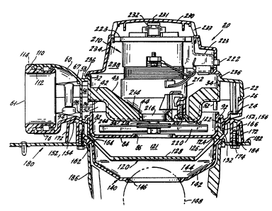
Figs. 1-3 of the first embodiment of the
blower 20 shows th~t the blower generally is comprised
S of sn e~ternal housing, including an upper blower
housing 22 which e~tends up toward the motor cap 230
~bove it down to the lower bearing 216 of the blower
~otor 210, ~nd a lower blower housing 24 beneath the
upper housing vhich e~tends beneath the blower fan 220
and the motor cap 230 over the motor 210. The blower
further includes the int~e shield 120 beneath the
lower blower hou~ing 24. There is an adapter 140
beneath the inta~e shield 120 to which the blo~er 20 is -
separabl~ and also sdjustabl~ attached for attaching
the blower to a surface li~e the lid 180 of a ~acuu~
cleaner 21.
The electric motor 210 drives the centrifugal
fan 220 to rotate. The fan dr~ws air through the inlet
opening 146 of the adapter 140 when the blower is
seated on a lid 180, through the air passages 126
through the intake shield 120, through the inlet 86 in
the bottom 84 of the lower blower housing 24, through
the centrifugal fan 220, around the chamber 244 in the
lower blower housing 24, through the plenum 54 in the
upper blower housing 22 and out the blower outlet 61.
These features of the blower 20 are now more
specifically described.
In Fig. 1, the region of the blower at the
lower right in the Figure i5 not in the plane of the
cross sectional view o~ Fig. 1, but rather is rotated
,, . ~ . ~
.~. ~ .~: . -
:~ :. .. - . .
. :. : '' ~ " .: ~ . ~
. . . .
--" 1331871
90 from that plane. Fig. l-appears in this way for
more clearly illustrating the complete assembly of the
blower.
The upper blower housing 22 and the lower
S blower housing 24 sealingly meet at the seal line 26
e~tending around the entire housing into the upper
blower housing 22 as well.
- The upper housing 22 is shown in Figs. 1, 3,
~ ~nd 5. It includes an annular top edge 32 that is
sealingly received in the lower end of the motor C8p
flange 236. an annular sidewall 34 defines the
sidewall of the chamber 238 in which the blower motor
210 is disposed. Beneath the sidewall 34, the bottom -
of the upper housing 22 is defined by the annular outer
port~on 36 which tends in from the siaewall to the
depressed cup portion 38. In the cup 38 are defined a
plurality of fins ~2 with inclined top edges ~3 which
together define a se~t for the bottom 214 of the
housing of the motor 210.
The cup 38 has a central opening 44
surrounded by an upstanding collar 46 which receives ~- -
the lower bearing 216 of the motor 210 and seals around -~
it, essentially preventing air flow past the floor 36,
38 of the upper housing 22 and into the chamber 238 in
which the motor 210 is disposed.
Depending down from the annular portion 36 of
the floor outward of the cup 38 are a plurality of
vanes 52 which are each oriented obliquely to the
circle of the array of vanes. Such vanes are
conventionally used in centrifugal fan arrangements, as
,- ~., - -
1331871
in vacuum cleanerc, for directing the exit air flow from the
centrifugal fan to circulate around outside the vane array.
Outward of the sidewall 34 and the botto~ 36 of the chaaber
238 for the aotor, the upper housing defines an open annular
plenu~ S4. The plenum is open around the entire peripheral
wall 34 80 that air can circulate completely around the array
52 of vanes. Outward of the peripheral wall 34, the upper
housing has an upper wall 58 which encloses and defines the
upper side of the plenum 54.
At one side of the upper hous~ng 22 is defined a
~e icylinder, partial tube, outlet section 60 which
cooperates with the seaicylinder outlet section 76 of the
lower housing 24 to define the blower outlet 61 from the
~S plenua 54.
An arcuate wall 67 pro~ects down fro~ the upper wall 58
of the hou~ing and ~u~t inside the opening at the outlet
~ection 60 for preventing a user's hands or foreign articles
fro ~oving directly into the upper housing.
At two opposite sides 63 of the upper housing 22, the
housing is widened and shaped to define the hand grip
openings 64 which cooperate with siailarly placed hand grip
2S openings 78 on the lower housing 24. The blower is attached
to and reaovea froa a lid 180 by rotatinq the blower, for
Ya ple, and the hand grips 6~ enable the operator to rotate
the blower housing. They also provide ~eans for easily
carrying the portable blower. Two hand grips 64 are provided
for providing maximum versatility in holding the blower and
in
- 12 -
~- ... . . -
~,"~ ~ "
~,, ,, .. , , ..
.~ ~ -- - ' - .
. .
. - -': - .
~, ,, . - .
: ~ .
- 13 -
1331871
directing the outlet 61 from the blower in any
orientation and direction.
Tbe upper housing has a pair of short height
bosses 68 beneath it in ~hich are disposed the head~ of
screws 69 which hold the motor 210 to the upper blower
housing.
The lower blower ho w ing 24 in Figs. 6 and 7
i~ open topped to mate ~ith the open botto~ of the
upper housing 22. The lo~er housing has the same
esternal profile 72 as the profile 73 of the upper
housing, and the upper and lower housing~ meet at the
respectivc profiled engaqeoent edges 74 on the lower
housing and 75 on the upper ho w ing to be secured
toq-ther. In this ~ay, the upper and lower housings
together define th pl-nu~ 5~, 2~
At a position correfipondin~ to the position
around the upp r hou ing of the outl-t ~ect~on 60, the
lo~er how ing has a respecti~e sed cylinaer, partial
tube, outlet section 76 which cooperates ~ith the
outlet section 60 to define a conplete cylindrical
outlet 61 from the plenum 54. The wide opposite sides
77 of the lower housing are shaped to define and
complete the openings 78 or the hand grips of the
entire blower housing ~hen it is assembled.
-~ 25 The lover housing defines a cup li~e ch~ber
in which the centrifugal fan 220 is disposed. ~hat
chamber has the annular wall 82 which surrounds and
supports the annular floor 84 which is disposed beneath
the fan. At the center of the floor 84 is an inlet ~-
opening 86 for air to flow to the underside of the
1331871
- 14 -
centrifugal fan 220. Outward of the annular wall 82, .
the lower housing has an annular slot 92 into which the
periphery 122 of the intake shield 120 is spin ~elded.
~adially further outward, the underside of the lower
housing at 94 is configured to cooperate with the
adapter 140 on which the blower is seated.
Inward of the outlet section 76, directly
beneath, projecting toward ~nd meeting the depcnding
protective wall 67 is the upstanding, arcuate
protective wall 98 in the lower housing. The walls 61
- and 98 define a barrier against entrance of fingers or
objects through the open pathway defined by the
semicylinders 60 and ~6.
Detent recesses 102 and 104 at diametrically
opposite positions around the lower blo~er housing 2~
establish the orient~tion of the blower with respect to
the lid 180, as is described below. Screw holes 106
around the lower housinq cooperate ~ith corresponding
openings 193 in the upper housing for receiving screws
for securing the housinqs together.
To complete the outlet cylinder 61, a ferrule
110 has a body 112 that extends into the semicylinders
60 and 76 and includes end clamping slot 114 which
cl~mps the outer ends of the outlet sections 60, 76,
thereby forming the unitary outlet 61 from the blower
housing.
Beneath the lower housing 24 is disposed an
intake shield 120 shown in Figs. 8 and 9. It is
generally cup shaped. Its upper annular periphery 122
is installed in and spin welded into the annular groove
~ .
2~
'' `', .~
: ` ' `' ` . . ~ ' ` `
~ ,
1331871
- 15 -
92 at the underside of the lower blo~er housing 24, so
that the intake shield ls integrated with the lower
housing 24 This avoias air leakage past the edge of ~ -
the intake shield 120 The shiela has an inclin d
peripheral wall 124 in which is defined a grill of
narrow width air passage openings 126 for permitting
entrance of air to the ~nlet 86 into the lower ho w ing
2~. The grill openings 126 are narro~ed to prevent the
entrance of fingers or articl-s through the grill 126
~hen the blo~er 20 is s-paratea fro~ the lid 180 When
the blower is ~eparated, ~hiela 120 serves as one -
e~posed side of the blower. The intake ~hield 120 has
a gcnerally flat bottQ 128 The grill openings 126
are not pri arily in that surface 128 If the blower
is operated whil- the flat botto~ 128 of its intake
; shield is on a surface or i8 resting against the person
carrying and w ing the blower, this contact will not
interfere with the inflow of air through the qrill
openings 126, and the user'fi clothing, for example,
~ould not be undesirably pulled into the grill openings
126
Two arcuate flanges 132 extend part way
around the intake shield 120 The flanges 132 together
underlie and define a bayonet type locking arrangement
~ith cooperating flanges 166 in the adapter 140. This
enables the intake shield and the entire blower housing
to be held securely to the lid 180 The ends 135 of
the flanges 132 meet the bloc~ing walls 167 at the ends
of the adapter flanges 166 when it is attempted to
rotate the blower housing counterclockwise
- 1331871 `.
. . .
- 16 -
An adapter 140 shown in Figs. 10 and 11 is
disposed between the iLntake shiela 120 and the lid 180.
The adapter 140 includes the ~ottom cover 142 which is
generally cup shaped and e~tends far enough into the
lid to define a plenum 144 between the cover 142 and
the intake shield 120 above it. There is an inlet
opening 146 through the floor 142 of the cover for air
to enter the blower when the ball float 148, which is
supported in the standard ball float support cage 186
of the lid 180, is down, out of the opening 146. The
~dapter e~tends to its peripheral flange 152 which has
opposite wide, rounded sections 154 and narrower
s tions 156. The flange 152 e~tends up to and seats
securel~ against the edqe 162 of the opening into the
lid 180 in which the adapter 140 is disposed to effect
a vacuum se~l.
There is a vacuu~ seal at 164 between the
intake shield 120 and the adapter 140 which prevents
loss of vacuum from the plenum 144 above the adapter
140 and from the space 121 above the intake shield 120.
The vacuum that develops when the motor 210 is
operating draws the adapter 140 up toward the blower
housing 20 which effects the two seals at 162 and 164.
The adapter 140 has at opposite sides a
respective pair of arcuate inwardly directed flanges
166 for overhanging the cooperating flanges 132 on the
intake shield 120. As seen in Fig. 10, the adapter
peripheral flange 152 iis tall. The flanges 166 are at
two arcuate positions around the narrowed width regions
156 of the flange 152. At one end of each adapter
, -
.
' . '-~
1331871
- 17 -
flange 166 is a blocking wall 167 which is abutted by
the end 135 of an intake shield flange 132 if it is
attempted to engage the flanges 132 and 166 by counter-
clockwise rotation of the blower. They are engageable
only by clockwise rotation and are disengageable only
by counterclockwise rotation.
At spaced intervals beneath the flange 152,
there are a plurality of hollow, open bottomed bosses
172 for receiving the shanks of respective screws 174
~hich are screwed through respective holes 184 in the
top 182 of th~ lid 180 and into the interior of the
bosses 172, thereby securinq the adapter 140 to the
lid, so that the blower at its intake shield 120 may be
separated from the tank lid 180 while the adapter 140
remains ~ith the lid.
When the blower housing 20 is ~n one rotative
position, the flanges 132 and 166 overhang one another,
~s shown in Fig. 1, and this prevents raising of the
blower from the adapter. When the blower is rotated
counterclockwise 90~ from the flange overlapping
condition, the flanges 166 no longer overhang the
flanges 132, which frees the blower for being lifted
off the adapter.
The lid 180, shown in Figs. 1 and 2, is for a
tank type vacuum cleaner. The lid is removably secured
to the tank 188 in conventional fashion. The tank has
a suction inlet 191. The lid has a top surface 182
with holes 184 through it at locations aligned with the
bosses 172 in the adapter. Screws 174 pass through the
holes 184 in the lid and are screwed into the bosses
172 to secure the adapter to the top of the lid.
' - .t.
. ,
-; '~ ' :" ' -
- 18 -
1331871
As is known from U.S. Patent 4,185,974, the
lid has an integral lid cage 186 depending beneath it
which encloses the above described float ball 148 and
which also defines a support for a standard annular
filter 189 that is placed o~er the lid cage prior to
operation of the unit in order to filter air being
sucked out of the tan~ 188.
The blower housing 20, together with the
~otor 210 and the inta~e shield 120 are held to the
adapter 1~0 and the lid 180 by the above described
cooperation of the flanges 132 and 166. A releasable
spring latch arrangement 190 shown in Figs. 11-14 holds
th in one of two loc~ed together rotative
orientations. The adapter supports a single latching
arrange~ent 190 in opening 19~.
The lower blower housinq 2~ has at its
- undersiae (Fig. 7) the t~o diametrically opposite
openings 102 and 10~ which cooperate ~ith the
arrangement 190 so that the blower outlet ~ay face in
either of two opposite directions. The recesses at
102, 104 are depressed into th bottom of the lo~er
housing to define respective receptacles for the detent
~- latching button 198, described belo~. The bottoms of
the recesses 102, 104 have holes through which pass
screws 192 ~hich join the lower housing 24 into bosses
193 of the upper housing. Screws also pass through the
other holes 106 in the lower housing into receivinq
bosses in the upper housing. ~-
Referring to Fig. 12, the releasable latching
àrrangement 190 is hel~1 between the top 182 and the
_,, . - ' '
.,
-- 1 9 -- : .
Ii 1331871 :-
adapter 140 There is an opening 194 in the bottom of
the adapter which guides the detent button 198 for
vertical movement into the recess 104 The detent
button 198 i8 bi~sed upwardly into the recess 104 in
the lower housing 24 by the spring 202 which is housed
inside the button 198 and presses up upon the button
and down against the lid 182 The button 198 includes
a ~olded lateral estension 204, which engages an
overhanging flange 206 on the adapter 140 to define the
ax~um extent of the upward ~otion of the button 198
When the button 198 is up, it is received in the recess
10~ in the lower housing This holds the blower
aga~nst rotat~on and establishes a particular rotative
orientation for the blower ~ith respect to the adapter
and lid T&e dia~etric~lly opposite recess 102 Day
~ alternatively be the one to receive the button 198 ~hen
I ~ th~ blo~er i8 rotated 180 fro~ th t orientation with
the button in recess 104 The recesses 102 and 104 are
~; placed so that with the button 198 disposed in either
` 20 recess 102 and recess 10~ in the lower housing, the
~` flanges 132, 166 are completely overlapped, for holding
the blower to the lid -~
The extension 204 on the button 198 is a -~-
manually operable button which ~ay be depressed by the -
user to release the loc~ing connection between the
adapter 140 and the lower housing 24 Once this
connection is released, the lower housing and thus the ~-~
entire blower 20 can be rotated with the hand grips 64,
78 until the cooperating overhanging flanges 132, 166
have moved so that they no longer overhang, which
_ables the blower to be lifted out of the adapter
~F,~` ` . . - ' : ,.
,~ . -. - .. - - .. -
133187~
This embodiment of a blower employs a conventional
electric blower motor 210 That motor has one external fan
220 for the blower air and a second internal fan, not ~hown,
for cooling the ~otor The aotor is seated on the inclined
odges 43 of the plurality of fins 42 in the uppsr housing 22
Tho ~otor 210 includes its own lower housing 212 with ~
conically shaped lower wall 214 which seats on the edges 43
of tho fin~ The ~otor shaft 218 is supported in a lower
boaring 216, tho oxterior of which is held in tho opening 44
at the botto~ of the upper hou~inq The ~otor shaft 218 is
~ d to and drives the conventional centrifugal fan 220 to
rot~t in the cha~b~r 2~4 in th lower housing Tho ~anually
operabl- electric switch 222 at the exterior of tho ~otor cap
i~ op rated to turn on the ~otor to drive tho fan Atop the
tor i~ a tor cov r 223 which closes th rotor and also
hold~ tho otor in placo insido tho ~otor cover
Bxt rnal to tho tor 210 i~ the enclo ing otor cap 230
~hich cov r~ ov r the top end Or the tor including th
upp r b-~ring 232 for th ~otor ~baft 218 Tho top 231 o~
th tor cap is sentially closod, ~o that if tho otor cap
re ts on a surface or presses against the clothing of a
p r on who carri the blower, air is not blockod fro~
ntering tho cap through the cooling air inflow vents 233 on
the ~ide of the cap and near the top Th cap extends down
along it~ side wall 234 to its poripheral flange 236 which
wraps over and substantially seals to the flange 32 at
- 20 -
~,.~ . --- - :
.~ ' ' ' - - ' ':
. . . -- ::'
1331871
- 21 -
the top of the upper blower housing 22. In known
manner, this creates an enclosed cooling air outlet
plenum 238 for the cooling air that has passed through
and then exited from the motor 210. The exhausted
cooling air exits through other vents from the plenum
238. ~he plenum 238 is separated by the closed bottom
36, 38 of the upper housing 22 from the main air
pathway through the blower.
The main pathway of air through the blower
is from the esterior of the blower, which may be the
interior of tble tank 188 if the blower is on the tank,
or other~ise from the ambient, through the sealable
opening 1~6 in the botto~ of the adapter 140, through
the plenu~ between the adapter and the intake
shiela 120, through the passage openings 126 in the
siae w~ll 12~ of the intake shield through the ch~ber
121 abDve thR intake shield 120, through the entrance
86 in the botto~ 8- of the lower ho w ing, axially into
and then radially and centrifugally out of the
centrifu~al fan 220, laterally into the plenum 2~
above and around the fan 220 and within the sidewall 82
of the lower housing, past the vanes 52 of the upper
housing, beneath the bottom 36, 38 and outside the
sidewall 34 of the upper housing 22, through the plenum
54, and through the cylindrical outlet 61. With the
blower removed from the adapter, air enters the blower
through the grill passage openings 126 in the intake
shield 120 and then follows the same path.
3s
.
~:~ , ,~,'.. . .
133l87l
A second blower embodiment 250 is shown in
Fig. 15. The modification uses a larger size
centrifugal fan 252 generating a higher CFM airflow.
This, in turn, means that the fan should be raised
higher with respect to the blower housing than the fan
220 of the first embodiment. The elements of this
second blower are similar to and function similarly to
the elements in the first embodiment of the blower and
~re not described again. The adapter 254 is the same
as the adapter in the first embodiment. The intake
shield 256 functions similarly to the intake shield of
the first embodiment, although it is slightly flatter
because the lower blower housing is higher. The lower
blo~rer housing 260 is differently shaped from the lower
housing 24 of the first embodi~ ent for accolamodating
the differentlr shaped upper housing 270 and fan 252.
` In this embodiment, the lower housing h~s a bottaDI 262 ~-~
~rhich is less depressed than the bottam 84 of the lower
housing of the first embodiment, so that there is still
only a small clearance between the bottom of the fan
252 and the bottom 262 of the lower housing. In other
respects, the lower how ing corresponds to the lower
housing 24 of the first embodiment and is not further
- described.
In this en~odiment, the air pathway out of
the centrifugal fan is through the vanes 266, which, as
in the first embodiment, depend beneath the upper
housing 270 and then flow is into the chamber 268 which
surrounds the vànes 266. The airflow from the
centrifugal fan therefore does not first travel up to
tÇi~``-` ~ i ~ `` `.~- ` - ` :
''~
. ~
- 23 -
133187~
reach the outlet from the blower, as in the first
embodiment.
The upper housing 270 of this embodiment has
the features of the upper housing 22 of the first
S emkodiment, except that the upper housing 270 is taller
to accommodate the taller motor 274. Similarly, the
motor cap 276 is taller to accammodate the taller
~otor. In other respects, the second embodiment
generally is similar to the first embodiment.
Figs. 16-20 shows a third embodiment of a
blower 280 according to the invention. In this
embodiment, as contrasted with the first two
e~badiments, the tor 281 between the motor cap 300
and the upper housing 310 is not itself within its own
motor casing. Therefore, ~arious elements, including
the motor cap 300 and upper housing 310, cooperate to
bouse and seal the motor in the blower. ~he motor 281
is a conventional electric motor which is connected
~ith the centrifugal fan 282 for dri~ing the fan to
rotate. Around the top of the motor is disposed a
baffle 290 shown in Figs. 17 and 18, which includes an
annular ring 292 that extends around the top of the
,
motor and a shelf 294 around the ring, which shelf
terminates in its periphery 293 which is shaped to the
` 25 interior profile of the motor cap 300. Depending from
one side of the baffle 290 is a support 295, and
outward from the support 295 is the electrical switch
support 296 which receives a conventional electrical
operating switch 297 that is conventionally wired for
operating the blower motor 281.
- 24 -
1331871
The motor cap 300 shown in Figs. 19 and 20 is
placed around the baffle 290. The cap has an upper
peripheral flange 302 which seats on the top of the
baffle and positions and also presses down upon it.
The cap 300 extends down to its base periphery 306
which rests on top of the peripheral flange around the
upper blower housing 310. Screw connection 312 e~tends
between the motor cap and the upper housing into
appropriate bosses 313 defined in the upper housing.
At the side of the motor cap where the switch support
296 is found, the motor cap has an opening 314 which is
partially covered over from above to provide protection
for the switch 297 against water, rain and dirt.
~; The motor cap 300 has a top 316 with grill
li~e openings 318 which define an air inlet for
communication of air through the cooling air inlet 322
at the top of the motor 2U. As in the othor
embodiments, the motor cooling air inlet grill openings
318 open mostly at the lateral sides of the cap 300,
rather than at the top 316. If the motor housing side
is the side of the blower that is held against the body
of the user, the inlet openings 318 for cooling air are
not blocked by the user. The cover 300 also has a
grill of outlet openings 324 for eYhaust cooling air
which has passed through the motor. Internal baffles,
not shown, inside the motor cap separate the flows
through grill openings 318 and 324.
In this third embodiment, two sets of grill
openings are illustrated. The motor caps in the other
embodiments may also have two sets of grill openings
_ - '
.."` ',
`~:: ;''` . ' '
` 1331871
- 25 -
which are separated by appropriate internal baffles
within the motor cap, not shown, as this is
S conventional.
Removal of the few screws 312 between the
motor cap 300 and the upper housing 310 of the blower
provides access to the motor 281 and to the motor
switch 297 for easy servicing, without requiring
lo removal of any of the other elements. ~ollowing
removal of the motor cap, the motor 281, the switch
297, the power cords to the switch and motor and the
motor brushes, which are all ser~iceable parts, are
esposed to easy access. Then the parts and the motor
lS cap may be simply returned to position and the cap
reattached, closing the blower.
Another major difference between this
blower e~bodiment and that in the previous embodiments
related to the separation of the main airflow past the
blover fan 282 from the cooling airflow that has passed
through the motor. There is here a separate lower
motor housing 330 which e~tends completely around the
motor and is inside and above the upper blower housing
310, because the upper blower housing lacks the
supports for the motor that are found in the other
e~hodiments. The upper blower housing has downwardly
depending flange 336 which e~tends entirely around the
interior of that housing and includes an annular bottom
tab 338 which projects toward the lower motor housing
330. A resilient sealing gasket 340 is disposed
.
P~
~s,, .~ .
1331871
between the bottom tab 238 and the curved periphery 342 of
the lower motor housing. This provides a separating seal
between the cooling air above the lower motor housing 330,
which has been exhau6ted from the motor 281, on the one hand,
S and the ~ain airflow pagt the centrifugal fan 282 which ig
~oving through the outlet 350 from the blower, on the other
hand.
10
2S
~30
- 26 -
. - -