Note: Descriptions are shown in the official language in which they were submitted.
, ~002
133~3 :::
- ,- ~ ,~,
~_~
""" '
The present invention relate~ to an arrangement of
~pparatus lnt~nded for transpor~in~ objects along a gl~en
movement path ~n~ comprising a stand structur~, a slide
a~embly carried by the stand structure, and ~ gripping-
devi~e atkachment m~ans conn~ct~d to the ~lide as~e~bly,
said gripplnq ~e~ic~ be~ng intende~ ~o hold t~e object
durinq it~ move~ent along ~aifl path.
~o
whQn pressing sheet-metal components in a pres~ line, for :
instance ~h~et-metal compon~nt6 or the automobil~ ::
indu~try, variou~ kind~ of handling 2quipment i~ used for
removing th~ components from ~ pre~ and in~erting ~aid ~.
aomponents in the next p~ess in ~Aid press line. ~n thi~ ~
re~pe~t, it is important thA~ the comp4nents are lifted ~ :
vertlcally from ~h~ tool of ~he ~irs~ press and then : ~ ~:
transported hori~ont~lly and finally deposited, either . ~ :
dir~ctly into tho tool of the next press or onto a ;: ~:
~g conveyor arr~nge~ent, which transports th~ components to
an in~eed station loca~ed in front o~ the n~xt pre~s,
where a ~urther ~ransport a~range~nt int~oduces the
components into ~he pre~ tool. Whsn ~ee~ing ~nd removin~
the ~heot-m~al component~ into an~ ~rom the press tools
~, re~peatively, it ia i~portAnt ~hat move~ent o~ ~he
~omponent~ relativ~ to th~ pre6~ ~ool is purely vertical,
50 that the compone~ will be correctly position~d on the ~:~
tool ~nd 60 th~t the ~ool will not be damag~d by
erroneous posit~oning of ~he ~heet-me~al components.
~IQ Furthermore, the component6 ~hould be ~o~ed in~o and out ~ :
oP the presses horizontally, since thQ 8p~ce in tho
p~sBe~ i5 restricted in the vertical direction.
'3 `~
'~ : :; ' ~
', ''. '~' '
... "
~` ~ 3 ~
2 20615-910
Modern presses also operate at hlgh speeds, and consequently the
arrangement provlded for transferring the components between the
presses must work equally as quickly, in order to enable the full
capacity of the presses to be utilized. The transfer arrangement
must therefore work swiftly, in order to cooperate with modern
presses.
The object of the present invention is to provide a transfer
arrangement which will afford the requislte movement pattern and
which is able to operate at high speed and capable of moving at
high acceleration, so that each working operation can be carried
out in a relatively short time period.
The invention provides an arrangement for moving ob~ects along a
predetermined movement path, comprising a stand, a sllde-assembly
carried by said stand, and a gripping-device attachment means
connected to the slide assembly, said attachment means being
intended to support a said ob~ect during its movement along said
path, in which arrangement there is an elongated carrier movably
mounted on the stand, a first motor to move said carrler with
reciprocating movement along a first straight path, a second motor ~ ;
~or moving the ~lide assembly on the elongated carrier with
reciprocating movement along a second straight path, which is
substantially perpendicular to the fir~t path, said slide assembly
carrying one end of a link system which includes a first link-arm,
one end of which is attached to a drive shaft in the slide
assembly and the other end of which is connected to the centre of
a second link-arm whlch is twice as long as the first link-arm and
',', ~,, ~
':
~ 133~ 9~
. 2a 20615-910
the first end o~ which second link-arm forms a free end of the
llnk system, which is reciprocatingly moveable along a third
stralght path which ls perpendlcular to both the first path and ~ -
~he second pa~h and carries the attachment means, the second end
of the second link-arm being displaceably journalled for movement
in a direction which is perpendicular to the third path and
intersects the drive shaft of the link system; and a third motor :-
which is carried by the slide assembly and is drivlngly connected
to the drive shaft to rotate the drive shaft by aid of a gear and
a toothed belt which runs over a drlve pulley on the gear and a
guide pulley mounted on the drive shaft and having a considerably ~:
larger dlameter than the drive pulley.
The inventlve appara~us is capable of operatlng at the high
acceleratlons and speeds requlrad to enable each working operation
to be carried out in relatlvely short time periods, so that the :~
arrangement iB able to cooperate wlth modern presses operatlng at ;~
high capacltles.
~ .
The invention wlll now be descrlbed in more detall with reference :~
to the accompanying drawings, which lllu~trate an exemplifylng
embodiment of the lnventlve arrangement and in which ; ~
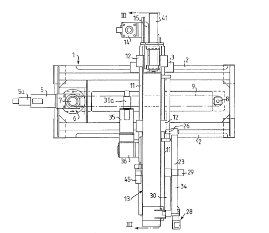
Figure 1 is a fxont view of the arrangement; ::` ~:
Flgure 2 is a side view of ~he arrangement lllustra~ed ln
::'~ ~'-;"
: ,, .": ,
'~
1~1 001
133~
Figur~ 1J and
Figu~e 3 ~ a seotional viewl~aken on th~ line I~ in
Figure 1.
The inven~iv~ arrangement ~llustrated in the dra~ings
~n~ludes a st~n~ 1~ which in,~hQ aa8e of the illu~trated
embodi~ent i~ intended ~o ~e.~ounte~, e.g. o~ a pre~
(not sho~n in ~he draw~ng). ~e stand 1 is provid~d with
guides ~ or rail~ which are Idicated ve~tically one a~ove
th~ other ~nd whl~h ax~en~ h~r,izontally alonq the
longitudinal ~dg~ o~ the stin,d 1.
The inventlve a~rangement fu~ther ~ompr~6e~ an elongated
carri~r 4 on ~hich carriag~ 3 are moun~ed ~or ~vement
along the guid~3s or rails 2, ~uc:h ~.; to ~nable the
elongatBd oarrier ~ to b~ mo~e~ along the guides 2 on tha
stand 1, with th~ aid of th~.c~r~iageB 3. This move~ent
o~ thé elongat~d carri~r 4 i~ acaompli~hed by mean~ n~ a
drlve motor 5 connected to a g~ar 6, whiah in turn
æQ carrias a driv~ roller 7~ A tObth~ b~lt ~ exten~ o~er
the drlve roller ~ an~ over a guide roller or pulley 8
l~cated At t~e oppo~ite ~nd o~ thg gt~nd 1~ ~aid bel~ 5
boing ~ttached ~o ~n attachme~ 10 on ~h~ ~lon~a~ed ;::
carrier 4.
' ,
Th~ elongated oarrier 4 i~ pr~vide~ with guida~ 11 whioh
ext~nd perp~nd~cular ~o the ~ e~ 2 on th~ stand l, but :~
in a plane parallel with th~ ~lane of said guldes 2. : ~
Runnin~ on th~ guides 11 are par~l~geB 12, which are ~: i
att~oh~d to a slide a~zmbly ~3 which is capable o~ ~
moving rectilin~a~l~ alonq the gui~es ll on the ~lo~ated ~.
carrier ~, with the ai~ of thq ca~iage~ 12. ~hi~
rec:tllinea~ movement of the ~;~ld~ assembly i~ , ;
Accompl~he~ by a drl~e mo~or 14, whlch is conn~cted to a
~ ~s
-
133~
gea~ 15 ~nounted on the elon~a~ed aarrier 4. The drive
motor 14 and the gear 15 drive ~ drive roll~r 16.
Ext~nding over ~he dri~e roll~r 16 and a guide roller or
pulley 17 located at the oth~r ~nd of tha ~31Ongated
5 cllrrler 4 i~ a tooth~d helt ~ B, which i~ attaahed to the
~;lide a~3~embly 13 by mean~; o~ an att~chment l9.
The slide aE~6embly 13 i8 pro~rid~d at its lGwer end (E;een
in the d~wing) with a ~ran~ver~e shaf~ 20 which extend~
parallel to ~he guide~ 2 on ~he ~tand 1. The ~h~f~
pro~ects laterally rom the slide a6semb1y 13 and one end
of a f irs~ link-arm Z1 is non-rotatz,bly at~ached ~o thi~
pro~ecting part of the e;haft 20. ~he o~her end of the
~ir~ link-arm 21 i~ pivotally aonnected ~o the centre of
1~ a ~econd link-a~m 23, by means o~ a pivot pin 22. The :~
~ir~t end o~ tne link-~rm 23, whlah is ~ free end, i~
provided with a pivo~ pin 24, where~s the other end of
ssld link-ar~ i~ provided with a pivot pin 25 for a slid~
piece 26 ~ournalled ~or m~vemqn~ along a r~d 27. The ro~
27 i8 ~ttAChed ~0 the ~lide ussem~ly 13 in a manner ~uch
~ to extend parall~l with the di~e~tlon of movement o~
the slide a~sembly 13, and ~uch tha~ the geometric axi~
o~ the rod will interse~t th~ geometr~c axi~ o~ the shaPt
20. ~he length o~ link-~rm 23 located b~tween the plvot
pin~ ~4 and 25 is twic~ as grea~ a~ ~he length of the
~lr~t link-arm 21 between the sha~t 20 and ~he pivo~ pin ;~
2~
~ho a~ore-d~scribe~ conotrUction Of the link ~ystem
3Q compri~lng the link-~rms 21 and 23 ~unction~ to i~part a
rectilinear movement ~ the ~irst~ ~ree end 24 of the
¦ ~econd lin~-arm 23 when ~he shaf~ 20 rota~esO Thi~
r~ct~linear movem~nt extend~ ~long a path which i~
p~pendicu~ar to b~th tne gui~eB 2 ~ the ~tand 1 and the
~ .,''
1~ 006
,, ~ .
133~
guide~ ll o~ the elongat~ad carrier 4.
-
Mounted at tha free end 24 oi~ the second linlc-arm 23 iB a
device 28 for the
attachment of a grippin~3 deviae. The gripping device i~
in~ended ~o grlp and carry ob~ac:ts, e . g . pressed sh~et-
metal oompohent~ or tran~;Perence o~ said objects
between two predetermine~ poin~. In order to ~n~ure that
~che atkachment device 2~ and the gripping device ~eaured
thereto do not ~ot~te when moved by ~eans o~ the 1 ink-
ann 21 and 23, the ~ir~i~ link-arm 21 forms part of a
parallologram-link sys~m which, in addition to the fix~t
llnlc-arm 21 C:omprises a link arm 2~ whose one end i8
conneated to the pin Z2 and whose o~her end i~ oonnec~
to one end o~ a link-Ar~n 30 by mnans o~ a pin 31. The
other ~nd o~ the link-arm 30 ~ ~onn~cted to an
attachment 33 on t~e slide a~sam~ly 13 by ~De~n~ of a pin
32. ~ho par~ o~ the ~ec:ond link-arm loc~ed between the
pin 2~ and the~ ~ree end 2~ al~o Porms part o~ a
;LQ p~r~llelogram-link systam, which also in~:ludes the :
~
chment device 2~, th~ link-arm 2~ and a link-arm 34 ;:
locJlted betwe~n the pln 31 ~rld the attaahnent device 2
Irhe shaf~ 20 15 rotated ~y mean~ o~ a drivq moto~ 35
.2E aonnected to a ge~r 3fi, which i~ bol~d on the 61ide .
~ombly 13 by m~3an~ o~ l;olts 36a and which carries ~
drive roller 37. A too~hed belt 38 extencl~: over the d~ive
roller 37 and also ovor a guide roller or pulley 39 which
~ attached to the i~ha~t 20. As will be seen ~rom Figure
3, the gu~de r~ller 39 has ~ mucn larg~r ~ia,meter than
the drive roller 37. Co~ querltly, any pl~y in the gear
3~ will decr~a~ed in ~o~r~spondence with ~h~ transmiisisi~m
ratio between ~le drive ~oll~r 37 and the guide roller
39, ~io that the accuracy o~ the angular po~ition o~ the
~0~7
, ,
13319~
~ha~ 20 will be increa~ed ~o ~ ~orrespon~ degree.
one condltion ~or achieving ~hi~ increase in aocuraay is
th~t the toothed b~lt 38 i~ ~ensloned wlth a force of
such magn~tude ~h~ ~he bel~ will remain tight
irrespective of the load ko w~ich the belt con~eivably ~-
can be ~ubjected during norw~l opera~on. ~his tensioning
of the belt can be e~ected 1~ va~iou~ wAyS, ~or instance ~ -
by pa~ing tha bol~s 3~a ~olding the gear 36 to t~e sll~e
assembly 13 th~ough elongated holæs which ena~l~ t~ ~e~r
36, and ~herewith also ~h~ driv~ roller 37, ~o be moved
tow~rd~ ~nd ~way ~rom the shaft ~0 and ~h~ guide rollcr
39.
' :,'`,.".-..
1~ The mas~ ~o be mov~d when moving the slide as~mbly along
the guide~ 11 is quite con~iderable. This ma s i~
compri~ed of thq slid~ aæ~e~bly 13, the link sy~tem 21-
27, 29-34, the attachmen~ device 28, the gripping device .~
and the objeat (no~ æhown) csrrl~d by the gripping .: ::
2Q de~ice. Por the pUrpOB~ o~ r~ducing ~he ~or~e6 requirod :;
to move thl~ ma~, the ~lide as~embly 13 i~ provi~ed with :~ ~:
n counterbalance arrangement comprising a gas spring 40 ~:;
~nd aa~o~lnted preæsure accu~ula~or 41 coupl~d between
~h~ 511de a~embly 13 and the ~longat~d cArri~r 4. ~h~
pres~ur~ accumulator 41 is ~ttached to the elongated
cArrio~ 4 an~ en~bles a balancing force to be exerted on
the ~lide assembly 13, this bAlanaing fo~ce b~lng changed
to only a relatlvely small ~xtent, ~e~pite the long
length of stroke of the ~lide as6embly 13. By a~justing
3~ the ~ressure in the pre~sur~ ~acu~ tor 41, it i~
po~ible to p~ovide a balancing ~f~ec~ whlch is adapt~d :.
to prevailing condition~, ~or ins~an~e ~or ~o~penfiating
f~r changes in the welght o~ the attachment d~vice and
th~ ~ripping device and th~ wei~ht o~ the ob~cts to b~
-
133~
tran~ferre~ By using ~he pr~ure accumulator 41 coupled
to th~ gas ~pring 40, whi~h ~ans that the counterbalance
arrange~nt will form ~ clo~ y~t~m, it ~s po~ibl~ ~o
~tilize a much higher pres~ur~ than i~ th~ system were
connect~d, for inotana~, to a co~pre~d-air ne~work. ~-
Thi~ enables the gas sp~in~ to be given smaller
~imen~on~, whioh in turn ~ean~ that the ma~s to be moved ~:
will al~ be ~maller.
0 ~or th~ purpo~e of balanoin~ ~he torque of the link
system 21-27, 2~-34 actin~ on the shaft 20, one end o~ a
ga~ ~p~ing 42 is pivotally conne~ted to the slide
a~embly 1~ and the other end o~ sa~ gas sp~ing is :~
pivot~lly aonnect~d to a pin 43 on the g~i~e roller 3~
lg in th~ nity o~ the par$phery thereor. A& will be seen
~rom ~i~ure 3, t~e pin 43 is ~o arrang~ that it~ ran~e
oi mo~ement 44 will lie ~y~e~ricall~ around a line which
conneot~ the ~ir~t end o~ the ga~ ~pring 42 to the ~ha~t
20. Con~equently, ~he gas spring 42 will o$~er increa~ed
~Q resl~tanco to rota~ion o~ the shaft 20 ~n eaah direc~ion,
~rom a centre positlon which corr~ponds to ~ centre ::
po~itlon o~ ~h~ attachment device 2~ wh~n ~a$d a~taahmen~ :
de~ce doe~ nut ap~ly torque to ~he ~ar~ 20. ~y using
pre~suro accumulator 45 whose pressure ~an be adjus~ed,
~g the d~sired balan~ing forc~ ~an be o~ta:ined wi~h th~ ald
o~ tho ga~ ~pri~g 42, such as to enable the drive motor ~:
35 ~nd the ~ar 3~ to have ~lativ~y small dim~n~ions,
daspite th~ ~act ~hat tha attachment ~evic~ 28 and the
gripping devic~ may ~e load~d ~lth relatlvely heavy
~Q ob~ect~. At ~h~ ~me time, the ~ce generated by the ga~
sprlng 42 a~t~ on the movea~l~ p~rts of tho driv~
arrangement in one and the same direction, 50 a~ to
inarease po~l~ioning ~ccuraoy. The qas ~prin~ 42 and ~e
p~e~ure accumulator 45 ~150 for~ a closed ~ystem which
.
,:
1~ 0~9
13319~ ~
ennble~ hi5~h pro~9ur~g to bQ u~ed, ~herowith ~n~bllng -
s~naller dim~n~;lon~3 tc be choE~en. Thl~3 also af~ord~ the
advantage of a ~3maller ma2:s to be tranQf erred .
:
5 'rhe use o~ il gear 36 having a rela~i~rely high
transmia~ion ratio and t~e u~ of a particular .
tran~mi~sion ~atio between the drive pulley 3~ and the
guide p~lley 3~ enable~ the drlve mo~or 35 u~ed to be ~ :
~igh-~peed motor. Thi~ mo~or will have ~mall dimensions,
lo and thu6 also a ~all ma~ and A low moment of i~ertia. ~ :-
ConQequen~ly, t~e drive motor 35 is able to accelerate
very qui~kly, ~hich is e~6ential in order to obtain the ~:
de~ired ~hort time period~ for ef~ecting moV~mQnt of the
llnk ~y~tem 21 27, 29-34~ Furthermore, the aforementioned ~ :~1~ reduction in the play in the gear 36 i~ al~o ac~ieved, so
a~ to enha~ce the ~ccur~cy.
. . .:
The rs4yrLs~Qn~i o~ the a~re-d~scribed ar~an~ement
will be apparent ~om the above description. The
~Q arrange~ent enables the atta~hment device 28 to be moved :.
along thre~ mutùally perpendicular path-~. Thu~, the
a~achment d~viae 28 aan be moved t~ any selected points
wi~hin the working range o~ ~he arrange~ent and an o~e~t :
aan be tran~err~d ~rom one point to another point along
predeter~lned movement pat~ when the three driv~ motors
5, 14 and 3~ ~re contr~lled in an ~pproprlat~ manne~. To
t~is cnd, the d~iv~ mot4re may be provi~ed with pulse
emttter~ 5a, 14~ and 3sa r~peotively adapted to transmit
in~ormation rela~inq ~o movem~nt of the mo~ors ~o a
~Q programmable control device (not ~hown) con~t~ucted ~o
control the mo~ors in ~ manner to obtain de~lred
move~nts. This con~rol d~vl~e may bR constructed in
vnrious WA~5 well known to those akilled in this art, and
a~noe auch a de~iae ~orm~ no part o~ the pr~ent
" ':
(i~l 010
-
1333 9~
invention, it will no~ be de~;cribed in ~.~3t~il here.
The invention is no~ re~tric~ed to the afo~e-desCribed
exempli~ylnq ~ odimer~t, and 3aodific~ionE3 c~n be ma~e
within the ~aope of the ~ollowing Claims. Fo~ ex~mple,
the inventive ~rrangement can he u~ed in widely d~f fering
fiel~ for holding ~nd movin~ dif~rent objec:ts in
acaordanc~ wlth de~:ir~ mov~men~ patterns.
~ ., .. . ~ ......
:,' ~' :. ,