Language selection

Search

Patent 1332006 Summary

Third-party information liability

Some of the information on this Web page has been provided by external sources. The Government of Canada is not responsible for the accuracy, reliability or currency of the information supplied by external sources. Users wishing to rely upon this information should consult directly with the source of the information. Content provided by external sources is not subject to official languages, privacy and accessibility requirements.

Claims and Abstract availability

Any discrepancies in the text and image of the Claims and Abstract are due to differing posting times. Text of the Claims and Abstract are posted:

  • At the time the application is open to public inspection;
  • At the time of issue of the patent (grant).
(12) Patent: (11) CA 1332006
(21) Application Number: 587726
(54) English Title: LIQUID WASTE TREATMENT SYSTEM
(54) French Title: SYSTEME DE TRAITEMENT DES DECHETS LIQUIDES
Status: Deemed expired
Bibliographic Data
(52) Canadian Patent Classification (CPC):
  • 362/12
(51) International Patent Classification (IPC):
  • C02F 3/02 (2006.01)
  • B01D 21/00 (2006.01)
  • B01D 21/01 (2006.01)
  • B01D 21/08 (2006.01)
(72) Inventors :
  • WERNER, ROY H. (United States of America)
  • GALGON, RANDY A. (United States of America)
  • DECKER, CLIFFORD J. (United States of America)
(73) Owners :
  • HAZLETON ENVIRONMENTAL PRODUCTS INC. (United States of America)
  • W. & P. INVESTMENTS, INC. (United States of America)
(71) Applicants :
(74) Agent: FETHERSTONHAUGH & CO.
(74) Associate agent:
(45) Issued: 1994-09-13
(22) Filed Date: 1989-01-09
Availability of licence: N/A
(25) Language of filing: English

Patent Cooperation Treaty (PCT): No

(30) Application Priority Data: None

Abstracts

English Abstract


ABSTRACT OF THE DISCLOSURE
A method of treating and progressively densifying liquid waste.
It comprises thoroughly mixing and aerating by a continuous mixer and/or
aerating raw water and chemical treating materials, discharging the
resulting mixture downwardly into a reaction compartment, thence
drawing the resulting material upwardly by means of an impeller and
gravity flow, then allowing a portion of the resulting denser sludge
to descend downwardly by gravity into a floc tunnel, thence in a
horizontal portion, further densifying and separating takes place. The
remaining portion is directed horizontally against inclined, closely
spaced parallel plates to clear the resulting fines mixture. Thereafter,
there is still further densifying the sludge. By this method, a
very dense sludge is obtained in a relatively small space.


Claims

Note: Claims are shown in the official language in which they were submitted.

I CLAIM:
1. Apparatus for treating water comprising a structure having
a plurality of adjoining compartments, inlet means for introducing and mix-
ing means for continuously mixing raw water, air, and chemical treating
agents at the top of a first compartment so as to move the mixture
downwardly through a reaction area in said first compartment, a second
compartment, a partition between the first and second compartments having
means defining a bottom opening through which mixture is led from the
bottom of said first compartment to the bottom of the adjoining second
compartment by means of gravity, a third compartment, an impeller fan
in said second compartment for hydraulically aiding the lifting through
gravity flow of material from the bottom to the top of said second
compartment, thence to the top of a third compartment, a floc tunnel
in said third compartment for classifying the sludge particles, and
additional sludge removing apparatus in said third compartment for
progressively densifying the sludge, and discharge means for the clar-
ified liquid together with a vertical baffle in said third compartment at
the end of a horizontal settling passageway prior to said sludge
removing apparatus, whereby some large solids are accumulated to trap
small size solids, and a recycle pump for removing said small size
particles and seeding the incoming mixture.
2. Apparatus for treatment of water as recited in claim 1
wherein said third compartment contains a plurality of parallel
spaced settling plates at the top thereof for settling fine particles of
sludge and other deposits exiting from said floc tunnel.
3. Apparatus as recited in claim 1 wherein said additional
sludge removing apparatus is together with a sludge removal means
at the bottom of said third compartment, comprising a network of
pipes which are perforated and supported in spaced relation on a
floor of said third compartment, and a pump connected to said pipe
network for further removing sludge from the third compartment.

Description

Note: Descriptions are shown in the official language in which they were submitted.


-` ~ 332006
LIQUID WASTE TREATMENT SYSTEM
This ~nYention relates to a liquld ~laste treatment system for
raw water or sludge.
BACKGROUND OF THE INVENTION
. .
In the past, llquid waste treatment systems comprised a number
of separate facilities for effesting different prscesses, involving
very h~gh cost and extens1ve land sites.
SUMMARY OF THE INVENTION
.
An object of the present invention is to overcome the above-named
disadvantages of existing liquid waste treatment systems by prov~ding
a compact, unitary construction completely enclosed in a single
building or module wherein the various steps of treatment are contained
in separate compartments which ad~oin each other and which steps
constitute substant~al improvements.
DETAILED DESCRIPTION OF THE DRAWINGS
__
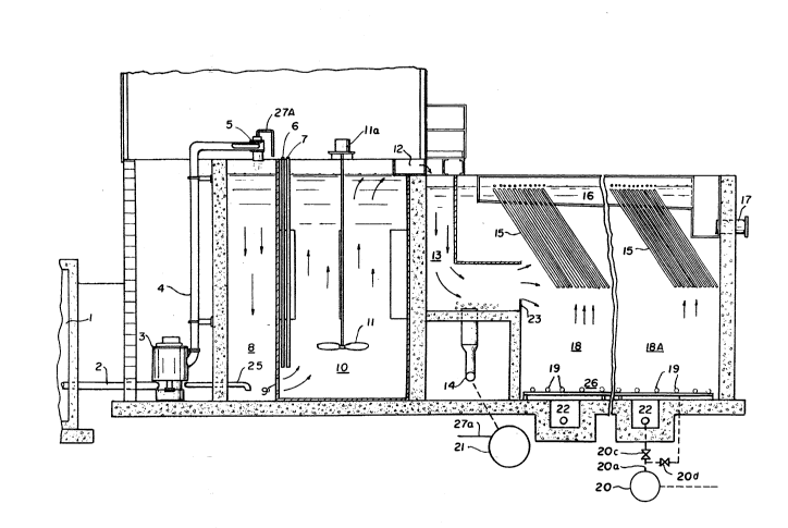
F~g. 1 is an elevational view, in vert~cal cross-section of a
liq!~id waste treatment system embodying the present ~nvention;
Fig. 2 is a transverse cross-sect~on taken at the right of
Flg. 1 and Figs. 3a and 3b are top part~al views and Fig. 3c ~s a control system.
OETAILED DESCRIPTION OF THE PREFERRED EMBODIMENT
Referring more particularly to Fig. 1 of the drawings, numer~l 1
denotes a' waste water storage or impoundment which is pumped by means
of pump 3 through pipes 2 and 4 to a mixer 5, often referred to by
applicant's trademark Turbo-Jett. Alternatively, such raw water or ';
waste water could be introduced into the mixer 5 by statlc head pressure.
The funct~on of m~xer 5 is for mlxing of reagents from reagent
pump 27 and pipes 27a (F~g. 3a) connected to the ~eagent storage tank'24a and pump 24
and/or aeration as will be described more fully hereinafter. Although most
reaction takes place in the mixer, additional reaction takes place in ~-
the reaction area 8 from which the mix leads through open~ng 9 leading
to the bottom of a floc tube 10. I.ime slurry caustic or other neutralizing
chem kals are pumped by reagent punnp 27 through pipes 27a to the mixer
~nlet,-the mixer 5 being capableof diffusing the chemical over the full
t area of the bore of the mixer. A typical mixer is shown in Roy'~- h'er~eP
Patent No.
~ .

~ 33~0n6
4,~74,477 ~ated Oct; 2, 1984,
Polymer introduction takes place through pipe 6 at the bsttom of
floc tube 10 at wh~ch preclpitates come ~n ~ntimate contact w~th the
polymers. At the same t~me, a proport~on of the sludge can be recycled
back for retreatment ~n mixer 5 through ~nlet l~ne 25.
The other portlon of the solids cont~nues to ~row 1n size and dens~ty
as they flow up through the floc tube 10 by means of ~mpeller 11
driven by a motor 11a, or by any other means for mechan kally induc~ng
upward current and/or gravity flow.
Once the sol~ds enter upper hor1zontal condu~t 12 and move
downwardly and hor~zontally ~n floc tunnel 13, the growth of the slze
and density of the solids continues to take place along with pr~mary
separation of water from solids once the slurry reaches the verticalty
ad~ustable baffle port~on 23 of the floc tunnel, wh~ch tunnel serves
as a part~cle class~fier. Reseeding or re~ntroduct~on of the sludge
to any precedlng area of treatment ~s possible by means of ~nlet dra~n
or suction l~ne 14 of sludge recirculating pump 21 wh~ch draws sludge ln
a downward direc,t~on and redistr~butes it to the desired locat~on. The
suct~on of the pump 21 ~s connected to the bottom of the floc tunnel
through 11ne 14. The discharge of pump 21 pumps to the ~nlet of the
m~xer 5 through p~pes 27a and 7 and~r fiottom'~f't~e ~l~c'tu~'la,
Beyond the end of the horizontal portion of the floc tunnel,
vert kally and angularly ~ncl~ned settling plates 15 a~d natural gravity
type settl~ng through d~recting the solids downwardly through areal8~18A
towards the sludge removal system. The seml-clear water is d1rected
outwardly and upwardly for further processlng and clar~f~cat~on 1n the
~ncl~nc~ plates 15. The fine particles move upwardly through area 18
andl~.A to be settled through area of settling plates 15. Once the
f~ne particles are removed~ the clear water enters collector trou~h 16
and passes out of the system through discharge pipe 17.
The concentrated sludge settle~s through 18 and 18A areas downwardly
towards the sludge removal area and 1s then sent for d~sposal or further
process~ng by the sludge removal sylstem 26, Recycl~ng sludge from the
sludge removal area to any previous portion of the system ~s poss~ble.
-2-

1 332006

The sludge removal system 26 comprises a piping network 1~ of a
multiplicity of parallel pipes supported on a pluralfty of supports
for spacing the piping network from the ~loor surface. The pipfng network.
l9 ~s connected to the suct~on side 20b of a pump 20(F~g. 2a having a
valve 20d (F~gs. 1 and 3a.) so as to suck sludge into th.e network through
inlet orifices, preferably at the bottom of the pipes and prefera~ly
spaced 2 or 3 feet apart. Pump 20 has an outlet 20a. The pipes may
be made of metal, fiberglass, or plast~c material.
While the entire network of pipes may be connected directly to
the suct~on pump, it is preferred instead, as shown in Fig. 3c, ~y
means of a control panel 28, density meter 29 and timer 30, to partit~on
the plpes into segments, each leading to a separate control valve 31',
thence to the suction side of sludge, backfla~h or'recycle pump 2lc:F~g. 3
By manually, or preferably electrically controlling the res~pecti:ve
control valves, such as by a timer 3Q'or sludge den~ity measurement
device., a sludge withdraw pattern ~hat more closely matches the pattern
of the settled sludge is obtained. Each valve 31'in the settling area
may be programmed to open for a different length of time by fully
automatic control operation. ThusD sequential operation o~ the control
valves select~vely connects the pump suction to variou~ segments o~ the
pipe. Overs~ze'd particles or foreign material discarded in the settling
area remain in place on the bottom of the basin until withdrawn from'
the floor drains 22 through valYe 20c.' The sludge system descrihed
includ~ng network 1~ does not'force oversized ~ater~al tnto the pump
inlet such'as to cause system blockage or damage to the sludge removal
system. Even if some of the ortfices become blocked,.there are
sufficient inlets to permit continued operation with min~mal chan~e tn
efficiency. Backflushing would remove overs'tze'parttcles frqm Qrifices
to ~e w~thdrawn with floor dra1n 22. Even thou~h segment inlets are
at varying distances from the suction'source,'the'or~ces'are small
in comparison with. the piping so that the flo~'rate into eacfi'ori~ice
~s controlled by the orifice siZe.

~ 332006

ThuS 1t w~ll be seen that a h~ghly efficlent and compact llqu~d
waste system has been prov~ded wh k h occupies only a fract~on of the
space of present l~qu~d waste systems at a fract~on of the cost.
Wh~le~jehave ~llustrated and descr~bed a s~ngle speclf~c embod1ment
of ourlnvent10n. 1t w~ll be understood that th~s 1s by way of lllustratlon
only and that var~ous changes and modif~cat~ons may be contemplated ~n
~ur 1nventlon wlth~n the scope of the follow~ng cla~ms.

Representative Drawing
A single figure which represents the drawing illustrating the invention.
Administrative Status

For a clearer understanding of the status of the application/patent presented on this page, the site Disclaimer , as well as the definitions for Patent , Administrative Status , Maintenance Fee  and Payment History  should be consulted.

Administrative Status

Title Date
Forecasted Issue Date 1994-09-13
(22) Filed 1989-01-09
(45) Issued 1994-09-13
Deemed Expired 2003-09-15

Abandonment History

There is no abandonment history.

Payment History

Fee Type Anniversary Year Due Date Amount Paid Paid Date
Application Fee $0.00 1989-01-09
Registration of a document - section 124 $0.00 1989-03-20
Registration of a document - section 124 $0.00 1991-05-07
Registration of a document - section 124 $0.00 1994-07-15
Maintenance Fee - Patent - Old Act 2 1996-09-13 $50.00 1996-06-06
Maintenance Fee - Patent - Old Act 3 1997-09-15 $100.00 1997-07-10
Maintenance Fee - Patent - Old Act 4 1998-09-14 $100.00 1998-09-14
Maintenance Fee - Patent - Old Act 5 1999-09-13 $150.00 1999-09-09
Maintenance Fee - Patent - Old Act 6 2000-09-13 $150.00 2000-08-22
Maintenance Fee - Patent - Old Act 7 2001-09-13 $150.00 2001-09-12
Owners on Record

Note: Records showing the ownership history in alphabetical order.

Current Owners on Record
HAZLETON ENVIRONMENTAL PRODUCTS INC.
W. & P. INVESTMENTS, INC.
Past Owners on Record
DECKER, CLIFFORD J.
GALGON, RANDY A.
HAZLETON ENVIRONMENTAL PRODUCTS INC.
WERNER, ROY H.
Past Owners that do not appear in the "Owners on Record" listing will appear in other documentation within the application.
Documents

To view selected files, please enter reCAPTCHA code :


To view images, click a link in the Document Description column. To download the documents, select one or more checkboxes in the first column and then click the "Download Selected in PDF format (Zip Archive)" or the "Download Selected as Single PDF" button.

List of published and non-published patent-specific documents on the CPD .

If you have any difficulty accessing content, you can call the Client Service Centre at 1-866-997-1936 or send them an e-mail at CIPO Client Service Centre.


Document
Description 
Date
(yyyy-mm-dd) 
Number of pages   Size of Image (KB) 
Office Letter 1991-02-19 1 17
Prosecution Correspondence 1993-01-05 1 26
Examiner Requisition 1992-11-18 1 54
Representative Drawing 2000-08-16 1 41
Drawings 1995-08-30 5 239
Claims 1995-08-30 1 49
Abstract 1995-08-30 1 35
Cover Page 1995-08-30 1 33
Description 1995-08-30 4 168
Fees 1998-09-14 1 49
Fees 1999-09-09 1 37
Fees 1996-06-06 1 44