Note: Descriptions are shown in the official language in which they were submitted.
`
13~202~
60/28~6~/01
Polymeric F~lm Ma~erial and lt~ Produ~tion
Wh~n forming bags and other articles from orientable
thermoplastic polymerle film material, varlo~s way~ are
S known and us~d for en~urln~ that the ~il~ mate~ial has
adequate stren~th for th~ p~rpo~es to which the ~ag will
be subjected. Pe~pi~e this, there i5 always a rlsk that
the ~in~l arti~le wil~ rupture during use when it is
:~ s~e~ted to sudden forces. ~r instance ~ sack ~hat has
be~n ~illed ~ith powder or granules may rupture when
dropped, ~he ~enden~y i~ greater with relati~ely rigid
polyme~s (considering the ~odulus of elasticity) such ~-
~polypropylene or high deneity polyethylene than ~ith less
rigid polymers such as low dens$ty pol~ethylQne~ but even
the low rigidlty polymers have a tendency to r~pt~re when
~ubjected to imp~ct. ~.
It would be desirable to ~ind a way of reducing ~e -.
tendencv for the ~ilm materi~l ~or article formed ~rom
it) to rupture undar impact, and to lncrease the energ~
20 absorption properties of th~ article. ~:
The prQsent ln~ention is concerned with ways Of ;:~
~preading ~he ten~ion and other ~o~ces in a ilm material
in ~uch a wa~ AS to mini~lse the rlsk of rupture. ::
In so~e instances, it would ~e desirable fox a ~ajor
2S proportion of the article, or even the entire article, to
~: be ~o~fied in th~s ~anner. ~o~ ;ns~ance it ca~ be ~:
~esirabl~ to modify. strapping formed fro~ ori~ntable film
~: mat~ri~l, especially strapping for parachute~, in order
to ~ini~isc the risk of ~pture under impact or to reduce
the 1 ~ act on the loa~ which the strapping is ln~end~d to
carry, or for si~ila~ reasons it can ~e desirable tO
~od~fy the entire sur~ce area (o~ parts o~ the entire
surfac~ are~) of large sheets, such as the hood of a :
pa~achute.
3S
133202~
In oth~r cases it i5 desira~le to modify ~inor
proportions of the film in selected areas. Thus
particular problems a~ise ~ith sacks or bags since
generally there is a particular zone in the bag ~t which
5 the bag is liable to star~ rupturin~, ~nd I re~e~ to this :~
as the rupture 20ne. It ~ould be p~ticularly ~esira~le :~
~o mod~f~ the bag in the rupt~re zone. Once ruptur~ng
has b~en initiated, the rupturing is l~able _o be
:propogated out of the rupt~e zone. The rupture zone, I
~ 10 ~or any partlcular con5truct~o~ ~f bag, can be postulated
: from theoretlcal consideration~ or, in a ~ore practical
aspect, can be deter~ined exper~entally bv dxopping so~e ¦
f~ ag~
The rupture zone is often a~soc~ated wi~h a seam in ;
15 the bag ln that the fil~ m~terlal ~d~acent tO a se~ is :~
often more liable to rupture than ~ aterial elsewhere
in the bag. It appears that the act of forming the seam
can adver~ely af~ect the propertles of the ~ material
ln the areas adjacent to the 6eam. Howe~er lt should be .~
ZO~ noted~ tbat the rupture zone may not extend acros~ the i,
ent~re length of ~he ~eam slnce in a conventlonal ~ag the .:~
r~pture zone ~ay be locatQ~ pri~ar~ly ln the ar~a mid-way
etween:the ends of the seam.
WSen the bag ls ~ g~ssetted bag that h/as an end 52al ` ;;~:
and tha~ compxise~ oppo~ea ou~er facesfinterconnQcted at
t~e~r side jedges~ b~f side ~u~sets,there tends to be
particula~ rupt~e 20~e at the junc~ion bet~een ~he side `~
gusset6 and the seam.
bag ma~ have ~ore than one rupture zone. For --
30 instance ~ ~ the ~ag is 6ea~ed at top and bottom then
: there wS 11 generally be a r~pture ~one associated with
each sea~ ~and at ~hl~h rupture is liXely durlng edge
drops) and if the bag ha~ side gussets then there will
generally bc a particular rupture zone also a~ ~he
~:
'~ 3 1 3 3 2 0 2 4
junction between the side gussets and the sea~ ~and at
~ich rupture is likely during flat ~rops).
It i~ of cou~ very well known to su~c~ the film
material from which the bag is made to v~rious
S oxientation and other treatment steps ~o as to impart
optimum propertles to lt but conventionalt~ the film
throughout the entire ~ag is of substantially unif4r~
properties, I~ i5 aleo ~ell known to em~oss the surface
of the fil~ either or visual app~arances or to
fa~ilitate ~t~cking of the fllm. Rowever conventional
ov~rall emhossing technl~ues do not give the ~mp~ovements
that would be de~ira~le~
Ori~ntable ther~oplas~ic poly~eric ~ aterial
a~cord,ing to the invention has at l~ast one stretched
lS zone in whiçh the material has ~een s~retched in a ~irst
direction and adjaeent to oppo3ite sides o~ this or each
zone, unstretched zones that ex~end ~,bstantially ln the
said ~lrst direction a~d in which ~he material is
3ubs~antially ~n~tretch~d.
~h~q in the ~vention ~he ~ilm ma~e~al i5 not of
unif~r~ stretch but is ins~ead given ~arlable de~rees of
stretch so ~s to provld~ the ~t least one stretched zone
and the plurAlity of substantially un,stretched zones.
~:~ These unstretched zones have a degree of stretch
significantly less than the stretch of the stretched
~ zone, ~ut they may be stretc~,ed slightly more ~han tha:~ origin~l fil~ ~aterial, before the stretchlng in the
stretch~d ~one. ~refera~ly there are a plurali~y of
these unstretched zones, eaah located betw~en a pair of
stretch,ed zone~.
! Generally the degree o~ stretch in stretched 20ne is
at least 10~ and genQrally a~ l~ast '0~, for in~tan,ce ~p
to 30 or 40~ or more relative ~o the initial film
materlal and preferably ~he ~ilm ~aterial in the
substantlally unstrstched, zones has little or no stretch,
1~32024
relative to the initial film material. The initial '~1
material must be orientable, but it may already have ~een .
oriented to a limited extent.
It is therefore necessary that, within each :
~tretched zone, the fi~m materlal ~hould have a longer
length than the adjacent unstretched zone. ~he film
material in thc st~etched z~ne ~ay co~pri~e a ~eries of
regularly or irregularly ar~anged pleats that extend
trans~erçel~ to the length o~ the stretched zone. A ~:
10 convenient way o forming each stretched zone comprises ~-:
pro~idlng a series of transver6ely extendinq positions at :
which the fil~ materi~l is stretched (i.e. it is
~tre~ched ln the said first dire~tion of the st~etched
one). In parti~ular, thi~ is ~est a~hie~ed by
15 ~tretching each zone by embo~sing the film material in - :`
that zone with tec~h that ~xtena tran3versely to t~ne first
direction. Often the ~tretched zones ~re longitudinal
and extend in the first d~rcct~on. :~
he invention can be ~ppliea to the e~ti~e area of a :~
sheet material in which e~ent, as indicated, there are
preferably a pl~rality of the stretched and uns~retched ~ ~
~o~es alternat~ng with one another. Each unstretch~d ` .
: zone may be in thQ form of a ri~bon that may ~e
rectil~near or zi~-~ag and which ~ay have a wid~h
25 typically of 5 to 150~ of the width of each stretched -~:
zone. Typically each un3tretched 20ne ~s a~ 'east O.~m ~:
wide and each stretched zone is ~t least 2mm and
preferabl, at leas~ 5mm ~-ide. When the unstre~ched ~anes
~: ~ a~e alt~rnating with the stretched zones, the unstretched
30 zones are generally not ~ore than abou~ Smm or ~ometi~es :~
10~ wide although they can be ~ide~, whilst the :::
st~etchea zones car. fre~uently be up to 20mm or 30mm
wid~, or mo~e. ;~
:~ The in~ention is of particular ~alue when applied to .
the avoidance of rupture of bags ~hat may be sacks1.
...~.
s 1332024
In ~his aspect of the invention, tubular orien~able
thermop~astic polymeric film matexlal th~t is or can be
s~aled ~o form a clo~ed bag havlng a ruptu~e zone at
which Xupture is lia~le to occur when th~ ~ag is
S s~bjected to rupture force~ by beln~ dropped when full is
provid~d and
the film m~terial adjacent the rup~ure zone in~ludes
shocX absorbing zone compri3in~
at 1 east one str~tched z~ne that e~tends in a
directlon leading sub~tantially away ~ro~ the rupt~re
zone and in whioh the film material has b~n ~tretched
s~bstantially in that tirect~on, and
a plurality o~ sub~tan~ially unstret~he~ zones
~d~acent ~o and extend~ng in subs~antially ~he sa~e
d~rec~ion as the or each ~tretched zone,
whereby the r~pture forc~s are tran~mitted away from
~: the rupture zone by the un~tre~ched zone~ and in'o the
: stretched zone or zone~.
~he tubular material of the in~ention ma~ be a
clo~ed bag, an open bag or an open tube that can ~e
sealed ~o form an open bag. ~or lnstan~e it may be a~
ena:ess tube that can b~ sealed and cut to eor~ a
pl~rality of tubes. The material is generally e~ended
in tubular form, ~ut if ~esired a shee~ ~ay be ~ide
~S seale~ ~o ~or~ the tubul~r ~aterial.
In ~hi~ aspect o~ the inven~ion the rup~ur~ 20ne is
preferaSly along a heat ~eal0d o~ stitched sea~ in the
final b~g, and thc shock a~sor~ing zone is pre~erably a
shoc~ absorber band t"SAB") tha~ ls separated from the
sea~ by ~n unstretohed area thro~h whi~h the rupt~re
force~ can ~e trans~itte~ in~o the shocX a~sorbe~ ba~d,
: and the band comprise~ a plurality of ribbons of
~ub~tantially un6tretched ma~erial extending
sub~tantially in th~ dire~tion of ~orce~ ~eting on the
~eam ~which norm~lly will ~e substantially perpendi~ular
6 1332o2~
to ~he seam) separated by strips of f ilm materlal that
ha~e be~n stretched s~bstantially in the sa~e direction
(i,e. nor~all~t 6ub~tanti~11y pcrpendicular to the seam).
~he ~idth of each unstretched ribbon does, for optlmum
p~operties, depend upon the partic~lar fil~ m~ter~als
being used but is typically in ~he ran~e 5 to 150~ of the
width of each adjacent stretched strip. As mentioned,
the direction of force~ ac~ing on the seam is ~ormall~
substa~t~ally perpendicul~ to the ~ea~. An e~ception to
this are seams made on the ~a~ in gussets.
Each ~stretched ribbon preferably e:~tends
cont~nuously ac~oss the entlre depth o~ the shocX
absorber band, in the diversion of the band perpendicular to the associated
seam. It may extend as a substantially straight line or as a zig-zag line
15 provided the changes of direction within the zig-zag line are not so great
as to prevent the transference of the load forces along the length of the
line.
~ hen the ~upture zone is the se~, it ~s desirable
fo~ the shoc~ absor~e~ band to be displaced ~ short
di~ance, for instance at lea~t l~m and o~ten at least
3cm $rom the seam, in order th~t the rupture forces at or
~djacent the sea~ can be dictributed over a ~seful width
of the shoek absorbing band. ~enerally, good ~esults are
obtained uhen th~ di~placem~nt is for instance not more
2S than lOc~ and often not more than 5 or 6cm. The depth of
the shock abso~bing band, i,e., the distance from ~ts
edge adjace~t the seam to its further~ost edge, is
typically ~n the range 3 to lOcm.
:: ~he parts of the seam where the ruptu~e forces are
30 most liablc to cause rupt~re are ~hose that are inwardly
displ~ced ~ro~ the side edges of the bag, in con~entional
bag desiqns, and eo it ca~ ~e ~nnecessary for the shoc~
ab~orbing ban~ to ext~nd to the o~termost edses.
Instead it ~ay ext~nd be~ween side positions tha~ are
displaced ~nwardly from the edge~ of the ba~.
~ 1332~2~
n ~ seco~d aspect of the invention, th~ orientable
~ilm materi~1 is in the form o~ a bag compri~ing opposed
o~ter fa~es in~erconne~ted at thcir ~ide edges b~ side
gussets. In thi4 case th~re ~s a par~icular rupture zo~e
5 at thc junction betweon the side gusse~s and a heat
scaled or s~itched end se~m tending to cau~e rupture ~hen
the bag is dropped on one of its f~at face3. Part or all
of the side gussets ~ay be in ~he form of one or more of
th~ described ~retched zones of logitudinally ~tret~hed
material whilst the uns~ret~hed zones of su~s~antially
unst~etched material may be ~it~in the gussets, ~or
instance alternatlng with s~retchea zones or at ~he
cent~e fold of the g~siset~, or may be at the extreme
edges of the ~us~ets or at the edges of the outer faces
lS of the ~ack, or may be displaced inwardly fro~ the outer
ed~e~ of the sack. This cons~ruc~ion means that load is
taken by ~he unstretched long$tudinal zones in o~
a~acen~ to the gussets but the otretched l~ngitudinal
zones in the gusset6 absorb shock and so protect ~he
ju~c~ions fro~ ruptu~e.
I now dlscuss in ~ore detail the avoldance of
rupture along a sea~. ~he i~pact strength of a seam in
~: a bag u~ually is one of the ~ost critic~l propext~es of
the bag. "Impact 6trength" here re~ers to drop test~
;~ 25 ~erfor~ed on th~ ~a~ filled wi~h the powaer or granule~
: for whlch ~t is ~nt~nded. ~orm~lly it will n~ ~e
possi~le to produce an adequate, simple "peel-type" heat
6eal (as opposed to the ~ore co~plicated "shear-type~
: he.at seals) in bags ~de 4ro~ relativel~ rigid poly~ers
I(re~errlng to the modulus of elasticity) such as
polyprop!rlene or hi~h densitv polyethylene, even ~hen the
mentioned ~o polymers have ~een modified ~y addition of
elastomer~ in amounts econo~ically and practically
acceptable,
~:
. ~ 1332024
The peel strength of ~uch heat seals, measured at
th~ l~w veloel~ie~ ~7hich are customary for tensile
testing, normally ~111 show v~lues at g~nerally th~ same
level or e~n hi~he~ than a h~at seal of low densi~y
polyethylen~ o~ slmilar thicknes~, while the impact
strength o~ ~he polypro~lene or high density
polyethylene seals is very inferior comp~red to low
density polyethylene ~eals.
By a study o~ these problems, I have Lound that the
1~ poor impact ~trength is conne~ed wi~h a pheno~enon that
may be e~uivalent to notch effect, namely, the
conc~ntration o4 peelin~ forces in a ~arrow linear are~
around the boundary of the contact-ace of the seal.
Add~ionally, th~re will often be a real no~ch effect due
~o imperfection in the shape o~ the ~eater bars ~sed for
formlng a heat seal. Where ~he ten~ile for~es are
concentrated, orien~ati~n will star~. If the peeling
action i3 slow this orien~ation will gradually de~elop
aw~ from the ~tarting line and will improve the stren~th
i~ this area. If, however, the rate of th~ peelin~
action e~ceeds a certaln ~rit~cal range, dependent on the
....
~aterial a~d of paxam~ters of the pre~ious heat seal -
operation, the progres~ of the orie~tation ~which is a
time dependent process) will ~ema~n co~flnad to a very :~
limited line~r zon~ in~tead of qradually w~de~ng this
zone. ~h~ high ~nergy action on an extre~ely limited
zone almo6t instantly causes a rupt~re~ .
I believe ~h- d~ 4ferent character o~ the o~ientation
proces~ when e~ected ~elow and above th~ ~ritical range
of peeling rates m~inly is a ~atter of heat developed ~y
,: ~ the ~tretching, the heat produced by the internal
~riction being high when the polymer is rigid. ~t ra~es
be~ow the critical range I believe there is tlme fo~ the
heat to be condueted into adjace~t por~ions of the film
60 as tO ~elp the orlentat~on to develop gradually and
'~. ..
1332~24
smooth'y. ~Qntrar~W~se~ a~ rates abo~e the critical
ran~q thQre ~ ~ not time enough 40r the heat to be
conducted away from th~ narro~ zone which is under the
influence o~ ~notch ef~ect~ (or similar) and the polymer
S will al~ost iD~tantly ~elt ~ithin this zone.
2crforat~ on8 c~use~ by the ~titchin~ ln a stitched
seal ~ay also ca~se wea~ne3ses a~d in ~his c~6e the
resifitace to rupt~re ~s very dependent on the velocity.
In the in~en~ion I ~ttempt to alter the
~haracterist~ of the bag material in a region near to
.. the sea~ with the aim that the energy released by
dropping the fllled bag sXould be guided to attack
another, prede~ermi~d and less sensitive ~a~t of the bag
~; conatruction.
It should be note~ that the described deficiency in
heat sealed bag~ from ri~id materials i9 particularly
pronounced i~ the ~aterial i~ oriented ~y stretchinq
below its melting point. I~ ~his connect~on it is known
that cross lami~ates of ~niaxially oriented high density .
poLyethylene or poly~ro W lene ~wh~ ch may contain minor
~: ~mounts o elastomer) with a suita~le, not too strong
bonding establlshed b~ween the plies, exhi~it high tear
propagation and impact stren~th ~alues in the film
t3elf, and glued bsgs ~ainly valve ba~s) o~ such cro~s~ ~ 25 laminates have ~ouna ~mportant commer~ial uses. It is
noted that xigidity, per se, is a desirable praperty for
a baq ~aterial. It is also Xnown that heat sealslin
these cross laminates ~how good peel strength when
~easured at thc rates normally used in tenslle tes~ing,
however, the imp~ct-peel-stre~th ~f such seals is
:~particularly lo~ maXing these otherwlse verr usef~1 :
materials comple~ely u~eles~ for simple ~elded ~ag
co~structions.
By ~tudies and theoretical ~ork ~ith oriented film
35 mate~ial, I have found thlat the above mentioned notch ~
;:
- lO 133202~
effect (or similar) is adversely co~ple~e~ted by the loss
o~ orientation in the area i~ediately adjacent to the
heat sealed area. ~he orientation, of co~rse, i.s also
lost in the ~eale~ a~ea itself, but sinc~ this area is
thicker this seems to be immaterial in this connection.)
In ~he oriented material i~self there is a hlgh
resistance against ~ur~her orlentatlo~ de~eloping, but
not so in the unoriented lineary zone adjacent to the
seal. ~herefore, not only the notch e~fect (or t~e
like) b~t also the ruin~ng of orientation ca~ses the
impact action or rupture forces to be confined to a very narrow zone. As
a re~ult, even material ~uch less rigid than high de~sity
polye~hylene or polyprop~lene, but in oriented state,
~ecomes useless for the sealed ~ag constructions here
1~ dealt with. -
U,S, patent no.4,039,364 concer~s a ~ethod o
prs~ucing ~ cross laminate of a type 2i~iferent rom theC~055 la~lnates mentioned ~bove. Rere each ply is
biaxially oriented, and instead of criss-crossing of
2~ direc~ions o unia:~ial orientation there is established
c~iss crossing of "graln of polymer~, which grai~ is
primarily proa~ced during the extrusion, but then through
the sequence of stretching steps, deflected to a
desirable zig~ag cou~se. As stated in the mentioned
patent, ~hese cxoss lamlnate6 generally are ~lell suited
~or heat sealing, a matter ~hich can be explained partly
the shrin~abil~ty ~ h~oh the heat sealed and the
a~jace~t areas increase in thickness, and pa~tly by the
special zig-~agging ~ra~ n of polymer. Nevertheless,
i~provement of ~he heat seals of such cross laminates are
sti~l de~irable, ~s the examples of ~hei pre6ent
zpecification will sho~.
F~rther, ac to ~he adverse ~ole of material r:gidity
in co~ection ~ith the impact strength o~ a seal, it
~hould ~e borne ln mlnd that what ma'~ers here is the
33202~
ri~idity at the temperatures exis~ing when the filled bag
is dropped, by inten~ or ~ccident. Thus, ~ven nor~al
low dsnsit~ polyethylene ls relativel~ rigid, e.g., at
-20C, and the drop strength ~ simple heat seals of lo~
S den6i~y polyeth~lene ~ags a~ that t~mperatures has been
fo~nd significantly inferior to tha~ esta~lished at roo~
~emp~atures. How~ver, -20~C and even lower
temperatu~es in many cases are normal ~or handling of
bags and, thereforeO there also exists a n~ed to
r~$nforce ~he seals of low density polye~hylene bags.
~ preferred ba~ (or tu~ula~ material for orming a
bag) ao¢ording to the in~entlon ~omprises, in combination
wtth a s~am, a ~rlpe pattern o~ embossmen~ along the
s~a~ adjacent but spaced ~rom the seam. The embossed
pattern consi~t~ of row6 o~ ~eeth-like indentations, in
~hich the fil~ is elongated malnly in the direction of
~he ~orce~ o~o~rring during a cr~tic~l type of drop, i.e.
nor~ally mainly perpendicularly to the seam, separat~d ~y
ri~bon~ of ~ubstantlally unaltered ~ material, ~o
~ause a shock abso~b~ng affect which protects the seam
~tself, when ~he filled bAg is dropped. The embossment
cau~es stretching.
The rlbbons of subst~ntially unalter~d film material
should b~ 6ufficiently narrow loo~pared to the teeth-like
indentations), and the degree of local elongation
produced by ~he embossment should be sufficiently high,
to ~ecure ~hat the descrlbed shock ab orbing effect
really is establishod a~d acts to retard the peeling
action, so that a certa~n orienta~ion can "calml~
d~velop in the area jus~ ad~acent to the seam. The
optimu~ design of thQ pattern ~which will hereafter be
callsd n tho shoc~ ab60rber band") depends on the
per~ormanee ~quirement~, the film chara~teristics, the
dimen~ion~ of the bag, ~he material which will be filled
in~o the ~a~, ~he degree of filling, the sealin~ or
133202~
- 12 -
~ewin~ procQ~s and the temperature at which the drop~ are
envisaged to take place. In any case, however, this design will
cau~e no principal problems for a skilled person working by
trial and error.
S In the accompanying drawings:
Figure 1 ahowR, on ~cale about 1:3, an open-mouth
pillow-bag, oupplied with two ~hock-absorber-bands, one near the
heat-~eal at the bottom, and one at the top near the region
predetermined for closing either by heat-~ealing or by sewing.
Figures 2A and B are details on approximately true scalo
of the bottom of the ~ack of Figure 1, A being a horizontal vlew
of the bag, and B a longitudinal, vertical section pas~ing
through a row of indentations.
Figure 3 i8 a modification of the shock-absorber-band of
Figure 2A, al80 shown in horizontal view and on about true scale.
Figure 4A are strain/stress diagrams taken on 5 specimen~
from the shock-absorbQr-band zone of a sack produced a~
described in Example 4.
,
Figure 4B ar- strain/stress diagrams for aompari~on, taken
on 5 specimen~ f:rom the samQ sack, but out~ide th
~shock~absorb~r-band~ zone.
;~ Flgures 5A and B on the same sheet as Figure 1 ~how
dlfferent sections of a set of embossment whee}~ (rollers)
~`suitable for making the shock-absorber-band. Figur SA is a
~` 25 ~ection through b-b of Pigure SB, and Figure 5B i~ a section
through a-a of Figure 5A.
Figure 6 i8 a per~pective view on approximately true ~cale
showing a corner of a gussetted bag, in which the gusset i~
supplied with an embossment to eliminate the critical ten~ion
which otherwise occurs at the intersection between the seam and
the innermost fold of the gusset.
The ribbon~ of unaltered fil~ material may be generally
~traightline ribbon~ (reference to Figures 1 and 2a) or may be
generally sig-sagging a~ by staggered embossment (referena- to
.
133202~
- 12a -
Figure 3) The former ~ake6 the machining of embos~mQnt tool~
easiQr, while the latter enables the ~ost e~ficient ~hock
absorption effQct, which may be needed wh~n th~ material i~
particularly rigid or particularly oriented
S In the dQscription above, the invention has been de6cribed
with a particular view to "peel-type~ heat seals However, a
similar problem of low impact strength often exist~ for
~ovorlap~ ~Qal~ in ca~e~ wh-n heat sealing of th ~atorial i~
diffieult, in particular whon the polym~r is oriontod Probl~
of a ~imilar nature can also ~ccur with overlapping seam~ bonded
by a ~elt adhesiv- and with super~onically produced soams The
invention therefore is useful in all such cases
Furtherf the invention i8 very advantageous in connection
with a sewn seam The strength of a ~ewn seam is essentiaily
lS~ dependent on the toar propagation strength in the film, which
aqain for stiff and/or oriented material is critically dependont
on th~ voloGity of tearing Thi~ also i~ true for tho abovo
~entioned two kind- of Gro~s laminates, which both show a high
toar propagation strength up t~ a certain critical range of
tearing rat-, but genorally poor tear propagation strength above
thi~ rang- The ~hock absorber band~ therefore ean
advantaqeou~ly be used to take up tho top of the impact aetion,
redueing the toaring rat- to a valuo below the critical rango
~;
,,, i I ~ ' ` '
"':~ ' ;
:
.'~ ,.
~' ~
` '?~ " ~
~ _~ 13 1332024
The shock abso~be. band is applicable to top and
bottom seams as well as side seams~ It hls been 'ound
~hat the forces exerted n~ar the corners of a ~illed bag
when the bag i~ dropped are alway~ xelatively small,
~onsequently ~he "shock ab~orber band" neQds not evtend
right to the ~dge~ of th~ ba~.
~ he in~Qntion further concerns the ~e~hod of
combining ~ea~ing o~ a bag with embossment in the
specific pattern which appears from the above d~scription
of the product, and ~o the combination of Seaming and
em~o~sing apparat~l~ for ¢arrying o~ ~his ~ethod.
Th~ shock ~bsorber band can be produced prior to,
simultaneous with o~ subsequen~ to the seaming process.
Thus, the shock absorber b~nd can ~e em~ossed either (al
on ~ilm be~ore tubing, or tb) on tube before bag making,
or ~c) on ~he bag before $illing, ox (d) on the filled
bag before thG f~nal sea~ is made, or ~e) after ~aking
: the ~inal seam. The invention also cover~ bag~ and
pre-stages of a bag (e,g., tubes for ~orm-and-fill) with
shoc~ absorber ~and alone, correctly located in relation
to a seam ~hich i 8 not yet made but intended to be made
later, ~his will us~ally be the top seam or both top
and bo~om seams ~ade in connec~ion with the ~illi~g
process. ~ag machines or form-~nd-fill ~achines using
pre ormed tu~e wi~h ~hock absorber b~nd can be supplied
with qy~ch~onisation devl~s SO as to ma~e the sea~s a~
the corr~ct locatlon~ in relation to the band~.
As mentlonod, a ~hock absorbe~ ~nd for the ~op seam
o~ an open mouth bag c'an be made a~ter the ~illing
process, in connection ~ith sea~ing of ~he bags. The
seami~g will ~s~ally take place by a conventional band
sealer or a conventional sewing machi~e, and in su~h
cases the shock absorber band is prefera~ly produced
continuou~ly between a set of emboss~ent wheels oÇ which
one can be ~upplied with a ~ala sur~ace pattern and the
14 1332024
oth~r with ~ corresponding female surface patt~rn. (See
Figure 5a nd b.) In other case~ it will often be
preferable to carry ou~ the embossment $ntermittently,
e.g., by use o~ a hydraulic or pneumatic pre~s, still
between male and ~emale formed sur~ace patterns.
If a transver~e 6hock absorber band is made b~l
embos~ment of tubular ~ilm, it may be dif~icu~t, witho~t
special measures, to open the ~ube for filling.
~heref~re, it is often advan~ageous to make at least the
s~ock absorber band ~or the top seam o~ an open mouth bag
whll~ the ba~ material i~ a fl~ film, and then convert
the flat film ~o B tube. In su~h cases, the m~chinery
~or embossm~nt ~an convenien~y be combined and
nchroniJed either wlth a printing machine or directly
15 with the bag making ~achine.
In this ca6e th~ slde seam i6 formed subseque~t to
the embossing of the shock absorber band for bottom
~: andlor top s~am~ and when the 6ide seam i~ produced
either by appli~atlon 0~ hot melt adhesive ar by heat
:20 seallng~ the applicat~o~ of hea~ will eause ~he
embos6ment to di~appear ~t the ~pot where the shoc~
abso~ber band Lnt~r~e~t~ with the side seam. Ho~er,
~his dQes not h~e ~n~ adver~e e~e~t provided the side
s~am i~ located very close to one edge of the ba~ since
. 2S ag ~entlon~d above the impact actlon is relatively 10W
~ .
nea~ to the corners of the ~aq .
he fact that only the unalt~red ribbons in the
shock-a~sor~er-band have to carxy the tensions
perpand~cula~ly to the ~eam, mean~ that the coefficient
of elasticity in ~hi~ band appears to be ~i~nificantl~
reduced, so that the band so to say acts a~ a rubb~r
band, and at the same time the all-over yield force in
he band will be red~ced. Both features wlll be further
explai~ca in conneet~on with Figure~ 1 to 4. ~he
reduction of yiald force can lead to permanent
- 1332024
. 15
deformations of the m~terial within the
shock-absorber-band ~v~n durin~ normal handl~ng or
storage of the bag, bu~ these deformations no~mall~ will
be r~latively un~mpo~tar~t, Aince they ~re con~lned .o the
5 rlaxrow band and, g~nerally speaking, terminate when the
bo~ses have be~ome straightened out. The ~alance
between the ne~ds for good drop performance and
sufficien~ resistance to yield is an intpor~ant factor to
consider in ~he choice of optlmurn pat~ern.
If the bag is intende~ to be carried ~anually and
maint~in ~ts ~hape a~ter this, the shock-absorber-band
6hou~d preferably ~ot traverse the bag sur~ace ~rom edge
to edge, but portion near the edges shoula be left
unembossed, ~hese ~eing of a width su~ficient to avoid
any sub~tantial deforma~ion when the filled b~ is llf~ed
a~ the corner~. As ~entioned earlier, there is no
essential need ~or ~hock~absorption effect at these
locat~ons, since in any case the peel forces will be
relat~vely lo~ ~ere when the bag is dropped.
In order t~ achieve a sufficiently important
shoc~-ab40rbing ~ffect, the pa~ern and depth of
exbos~mQnt should be adapted to give no l~ss than 15~ and
prefexably ~ore than 2$~ i~pro~emen~ of ncritical drop
height" for one drop cycle. ~Critical drop height" here
~:~25 ig de~ined as the drop hei~ht ~hi~h, statistically, is
the li~it be~een no-failu~e and failure, ~hen One bag
:~ith the relev~nt contents o~ powdere~ or granulated
: ~goods is dropped 6 time~ in the fol~owing cycle~
lat surface, ~) 2nd flat surfac~, (3~ 1st edge, (4)
2nd edge, (5) ~ot~om, ~6) top~
~`~owe~ex, w~th suita~le selection of pat~ern and
dep~h of embossment ~guidelines ~or this ~e~ection given
~:in sonnection with Fig~res 1 to 4~ th~ incr~ase in
critical drop helght for one drop cycle can in many cases
~e 50~ or 100~ or even more, withou~ causing any
~':
' ` 16 ~33202 4
essential damage of the capability to resiQt deormation
during handling and ~torage of the bag, ~mbossment of
the film materi~l in ba~s is ~nown ~or the purpose of
improving the anti~sl~p ch~ra~tQristlcs, which are
lmportant for stacking. For this purpose, how~ver, it
is important to select a type o e~bossmen~ whi~h onl,r
creates ~inimum reduction in coefficient of ela~ticlt~
and yield ~orce ~refer~ing ~o the apparent values as
further explained in connection wi~h Figures l ~o ~). A
1~ bag with the ~hock-absor~er-band can also, in order to
~mprove ~he anti-slip praperties, be supplied with an
additional embossment in other ~elected areas or
generally all-over, b~t in ~uch c~ses the pattern a~d
dep~h of emboss~ent ~n the shoc~-absorbcr-b~nd ~ust be
lS adapted to produce ~ subst~n~lally higher shock
absorption e~fec~. ~T~e basic features of ~hock
a~sorption ef~ect are expla~ned ~ore quantitativel~ in
: connection with the graphs in Figur~s 4A and 4~.)
A~ mentionQd in the introduction, gussetted sacks
~ith button and/or top heat seals have a particular,
: spot-~ormed rupture zone in or im~ediately adjacent to
each of he interse~tlcns between the lnnermos~ folds of
the gussets and ~he bottom o~ top heat seal. The rupture
in ~hese zones mainly occur3 when the fille~ sacX is
~S dropp~d on one of its ~lat ~aces. There are two reasons
for the tendency ~ pture in these spQts~ one ~hi~h one
~ i~ the ~udden ch~nge in th~ckne6s hetween the gussatted,
: 4-ply, part o~ the s~ck and the part which i~ not
: gusse~ted, i.e. ~s 2-ply. This change o~ thick~ess makes
thc heat-sealing particularl~ critical. Ano~her reason
,~. wh~ ruptur~ tends to occur in these ~pots is that, when
~he sack h~s ~een filled and the gusset there~ore has
unfolded to g~ve the sac~ brick-form, the p~ll on the
gusset at each corner o~ the sack has to ~e taken-up
m~inly by th¢ narrow spot ~here the heat-seal int~rsects
1~ 1332~2~
with the in~er~os~ ~old of the gusset. Then ~hen the
sack i8 dropped on o~e o~ its fl~t faces, the contents
becomes thrown out against ~he corner o~ the sacX, and
ths re~ultant pull on the ~usset in this corner
concentrates ln ~he narrow spot of intersec~ion.
Consequently, gussetted sacks ~annot ~ithstand ~lat drop~
from the sa~e maximum h~ights as simple "pillo~ 6acks" of
~imilar materi~l, unl~os sp~cial precautions are taken.
Th~s applies ~lso to gussetted sacks fro~ soft and
read~ly heat-seala~le materi~ u~h as ~DPE or LDP~.
In the known art, this problem i9 solved by
supplying each gussetted corner with two extra,
rectilinear heat-seal~, each one sealing one si~e of the
gusset to th~ corresponding outer ply of the ~a~k, and
1~ ~ach s~arti~g in the mentloned spot of intersection and
extending on bias, normally inclined 4S~ to the
: longitudinal direc~ion o the sack. ~ith these extra
heat-6eals, the gusset ~ill still ~old in the normal
way in the corner and ~ill give the sack ~ri~k-shape
durlng ~illing, but now the ~orces on the gusset in the
corner dur~ng a fl~t ~rop will become distributed ove~
th~ ent~re len~th of the two e~ra heat-s~als instead of
concent~ating on one spot.
A drawba~k of th~s com~only used precaution is the
r~latively long ti~e needed ~or the special ex~ra
~ heat-6ealing, which necessarily ~ncludes a ~ool~ng step
`~ before the ~wo ~ide6 of ths gusset meet each other again,
slnce otherwise they would fuse ~o~ether and f~rm one
~ngle se~
` 30 Therofo~e, the ext~a sealing procedur/ 3s more
conveniently, accordinq to this invention, su~stitut~d by
ap~lication of S-A-B to the gusse~s in the co~ne~s o~ the
sa~k~ Th~s S-A-s shoula not, in ~ssence, e~end into the
two outer plie6 of the sack, but be confined ~o the
3S
~ ~ la 1332024
gusset near the corner (hara refer~ing to the structure
' o~ the sack hefo~e unfolding of ~he gus~et).
Ideally, the unstretchQd ~ones or ~riSbons" in the
S-A-~ should all poin~ in the direction of the spot of
S interscction ~o as to point the same wa~ as the tens~ons
in the un~olded gu6~et ~ut in order to make the
con~truction of the toolG ~mplex the pattern of
embossm~nt can ~e li)ce in example 3, in which t},~
~ribbons" all ~xtend in the logitudinal direction of the
10 saclc. At least the "ribbons" near the innermost fold o~
tho gusset then malnly point towards the spot of
intersection.
A3 an add~ional advanta~e, the apparent s~rong
reduction of coeffi~ient of elasti~ity effe~ted by the
15 eTnbossment of the gusset~ near the corners of the sack
helps th~ ~ontents better to ~ill out the space ln the
corners and there~y the bri~k-shape becomes perfected.
Shoc3c-absorber band~ can optionally be ~sed in
:~ combina~c~oJl ~ith the em~os~ment of the gusse~ here
20 descri~ed. Thus, the oombined use of "gusset
embo~smen~" ~na ~ sho~k-absorber-band" described in
example 3 gave improv~ment ln critical drop height b~ a
fa~tor exceeding thr~e. The "gusse~ embossMent" i5
preferably carried out on ~lat ~ilm b~fo~e tubin~ or on
~lat tub~ before gussetting, but can also be calried out
: af~er gussetting, and even a~er bag maklng, provided ~he
~nte~nal o~ the bag is convenientl~ a~cessible.
An alternat~ve, and in so~e cases slmpler
precaution, which doe~ not t~uly fall under the above
montioned definition of shock-absor~er-band but utili~es
an analogous effect consists in stretching by e~bossment
the innermost fold o~ the gus~et lmmediately adjacent to
the bot~om andtor top seals, Thu~ tha gusset and the
adjacent ~aces of th~ ba~ can be cons~dere~ to be a
special form o~ the shocX a~sorblng ~on~ o~ the
.~",
~ :;
19
invention, which may extend from ~ position at or close
to the junction betwee~ the seam and ~he side gu~sets and
~hich need not extend substantially acro~ the width o~
the gusset~. The edges of the outer f~ces o~ the bag
and/or parts withln the gus~ may ser~e a~ the
substantially unstretched zone9 adj~cent t~ the stre~che~
zone, that i6 part or all o~ the area within the gussets.
Simultaneous embossment of the outer pli~s of ~he sack
may do no harm, but ma~es the procedure ~impler. This
embossm~nt in ~he gussets must be sufficientl~ deep
and/or ~ufficiently close to the seal, to pro~uce the
~ffect that a tension applied to the fold is essen~ially
~arr~ed ~way from the spot of intersection ~whe~e the
heat-s~aling as mentloned tends to be critical) and into
a part Oc the heat-~eal closer to the ed~e-face o~ the
sack.
Prefera~ly, this e~bos3ment should gradually
fade-off in the direction to~rds the edge in s~ch a
~nner as ~ distrib~te the forces up on the ~nnermost
fold of the gus~e~ over a wider part of the bottom or top
seal .
In ord~ ~o ensure a preclse location o~ this
embossm~n~ relati~e to the ~pot of int~rsection bet~een
~he inn~rmost fold and the bottom or top seal, this
e~ossment is mor~ convenicn~ly ~arried o~t
slmultaneously with the heat-sealing on the ~ame
apparatus, whlch may compri~e m~ans to detect the
tran~verse location of the innermost ~old and accordingly
~or auto~atic transv~rse ~djust~en~ or the loca~ion of
embossment.
~ 3 alrQady ment~oncd, the shock-ab~orb~r-band is
very suited for bags made ~rom the cro~-lam~na~e~
described in U.8. patent n~.4,039,~4. The ~ame ls true
~or the "gusset embossment~ desc~ibed above. u.S.
patent no,4,629,525 discloses improved compo~io~s for
133202~
cross-laminates of this type, consisting of two or more plies, of which
each normally has a main layer, a layer to facilitate lamination, and a seal
layer. The two embossment systems according to the present invention
can advantageously be used, separately or in combination, on bags from
these compositions. Thus, a particularly preferred main layer for use in
such laminated sheet for the bag of the invention is formed of a blend of
high molecular weight high density polyethylene with significantly lower
molecular weight low density polyethylene, the latter preferably being
selected from copolymers and/or branched polyethylenes which have the
io same or higher elongation of break (tested at room temperature under
slow s~retching) as the high molecular weight polyethylene and which are
capable of distinctly segregating, while forming a distinct microphase,
from the high molecular weight polyethylene on cooling of a molten
homogeneous blend of the components. The blending ratio of the
;~ 15 polyethylenes is preferably 25:75 to 75:25. The inclusion of
polypropylene having significantly lower molecular weight than the high
molecular weight polyethylene can also be advantageous, in amounts
from 0 to 70%, based on the combined weight of polypropylene and
both polyethylenes.
> `~
21 ~332024
The high molecular weight high density polyethylene (HMHDPE)
preferably has a melt flow index of about 0.2 or lower by ASTM D1238
condition E, and the low density polyethylene is preferably linear low
density polyethylene (LLDPE).
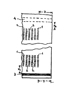
In Figures 1 through 3, (1) are rows of teeth-like indentations and
(2) unaltered (or substantially unaltered) ribbons~ (1) and (2) together
forming the shock-absorber-band (hereinafter abbreviated to S-A-B). (3)
; is the heat-seal at the bottom. At the top, (4) indicates the zone where
the bag is predetermined to become closed either by heat-sealing or by
0 sewing. There are relatively long distances X, and X2 from the S-A-B's
to (3) and (4) respectively, the lengths of which will be discussed below.
At each corner of the bag, a zone Y is preferably kept free of
embossment. Y should be calculated so that
::
,
~ .~
2~ 1332024
it is sufficient to avoid any essential deformatisn when
the filled bag is ~arried by the corner3 in ~he way by
Which it is intended tO be handl~d,
Edg~-droE~ is by ~ar the mos~ cri~ical kind of
5 dropping 'or top - and bo~tQm hea~-seals or sewn seams in
pillow baqs. (For gu~setted ba~s flat drop is rnore
critical due to the ~peci~l problem dealt with in
~orlr~ection with Fig~lre 6, ana for longitudinal seams
bottom-drop and top~drop are most critic~l). When the
ed~e o~ the bag f~lled with powder or gr~nules hits the
g~ound, th~ ~ontents are with great force spread
horizont~lly. A~ the moment ~he bag hits ~he ground,
the spxeading is ~onfined ~o take pla~e almost entire~y
perp~ndi~ularly to the len~h o~ ~he ba~, ~nd near top
and bottom the impaot on the ~lat surfaces o~ ~he bag
the~ will cause a high lon~itudinal pull, that ~eans
~trong peeling action on top and ~ottom seams. I have
found that this peeliny action is hlghest near the middle
of the seams, or somewha~ closer to the edge which hits
the ground. It is ver~l understandable tha~ the peeling
is near zero at t~e oorner. which aO no~ hit th~ g~ound,
but rather suxprising that i~ also is lo~ nea~ tho
corners which d~ hit the g~ound.
~he improYements achie~ed b~ use of the S-A-~ are
25 best understood bS~ ob~a~ation ~ the gxaphs in Figures
4A and B.
~ he ed~es of each of the specimens 11 to 14, of the
inv0n~ion, for the graphs in Figure 4A have been out
through the middle line of two unaltered ribbons (2) ar~d
30 each spe~ilnen comprises two rows o teethlike
indenta~lons ~1) with an unaltered ribbon ~2) hatween.
In total therefore, each specimen con~ists of two rows o~
teethlike indentations (1) and two unaltered ribbons ~2).
~hs speoimen width ~s 22mm~ The initial distance
betw~en the jAWS o the tensile testlng appaxatus is
133202~
23
50m~ and the specimen has S-~-B throughout this space.
~Th~ width o the S-A-B is also ~mm, see exampl~ 4.)
~he testin~ ~eloçity i~ 500mm/min ~ looo~ elongation per
min. In the graph~, lOm~ on t~e abscissa corr~ponds to
20% elongatlon.
~ he comparative set of graph~ Figure 4B ~as als~
made from 22m~ wid~ specimens 16 to 19 c~t fro~ parts of
the sack that are frRe of ~ho~k ab~orber band.
In the ran~e from ZQro to the deflexion point Y, the
~ibbons become elong~ed in el~s~ical manner, but b~gin
to y~eld at Y. In this range, ~mpari~on he~ween ~he
two sets of graphs shows that the 510pe in c~rves A is
almo~t qxactly half that o the curves s, in accordance
~ith the fact that ~ach ~i~bon in the S~A-~ in ~hi~
actual case (see e~a~ple 4) has been made with the sa~e
w~dth as each row of indentations, so th~t al~os~ exactly
half the width o~ the ~pecimen ~s under load. ~he ~lope
in th~ s range i~ a meaq~re of the coef~ic~nt of
el~ticity - for th~ e~bos~ed samples it is more correc~
to ~ay ~ppar~nt coe~icient o elasticity - and t~e
~r~ph~ d~monstra~e how the S-A-B make~ the ma~erial
appear mo~e rubber-like.
~ ith the fllm compositlon ussd in example 4, the
ratio between width o ri~bon and dl~lsion ih the ~-A-
~
could also h~ve been somewhat ~igher ~han the actuallyu~ed rat~o l: ~ and still w w ld ha~e ~iven satis~actory
im~rov~ments, while lt can be nece$sary to make the ratio
much low0r ~n case of m~ch s~ er composition~, e.g., to
: mak~ it 1~10 G~ even 1~20 ~s~e e~ample 1 in ~hich it was
necessary to use ratio 1:10).
!. Between defle~ion point Y and ~he next defl~xion
poin~ A, the ribbons are yielding, while ~.he indentations
still are ~lacX. A~ point A, ~he indentations are
~traightened out and b~gin to ~longate el~st~cally, while
24 ~33~024
the ri~bons continue yielding. ~t the last defle~ion
point B, th~ former Lndentations also start yielding.
The elongation in percent a~ A ~s ess~ntially equal
to th~ origihal str~tch ratio ~n the row of indentatio~s,
S in this case a~ou~ 28~ e~ualling ratlo 1.28
One important factor for the ~unc~ion ~f the S-A-B
i~ the apparcnt reductio~ of coefficient of ela~ticity
and yield poi~t, dealt ~th abo~e, which invltes the
impact to a~tack ~he S-A-B instead of at~acking the se~m.
Another i~po~tant ~actor is the energy absorbed ~y the
S-A-~ from zero ~o deflexion po~nt ~, which I call ~S-A-B
energy". ~his mu~t be sufficiently big to "paci~y" the
i~pact ~aused by the edge drop, so ~hat, after the S-A-B
ha~ng been in effect, the at~ack on the seam will not ~e
strong enough ~o ruin the latter.
The indenta~ions sho~ld pre~erabl~ be made as deep
a$ practically possible ~ ., the stretching ratio in
thc rows of ~ndentations highest po~sible) ~o that ~he
S-A-B ~nergy ~er width of ~he S-A-B becomes highest
pos6~1e Ifor an~ given pattern of embossm~nt) however,
t~ere a~ the fvllowing practical l~mitations:
(a~ the li~ited st~etchabil~ty of ~he film, in
connection with the required high process v~locities,
~b) the weakness of the teeth ~in&~ o~ ~he embos3men~
2~ devices.
~ ith the t~pes o~ cross-la~inates ~hich are
described ~n the examples, and wh~ch already ha~e been
stretchea in both direc~i~ns before the embos~ment in
ratios b~t~een about 1.4;1 and 1.6sl, I h~e fo~nd lt
di~f~cult to exceed rati~s 1.3sl or 1.4:1 when ma~in~ ~he
i n~lenéatlons, unless preheatin~ of the film is used in
th~ areas whlch are to be embossed, and rlormally I would
avold preheating ~hich i9 a complication o~ the proces~.
: Stretch ratios lower than a~out 1.3:1 are also applica~le
when ~aking the ro~s o indentation~, provided at least
'~.` 25 2 0 2 ~
15~, ~ut pre~erably ~ore than 25% i~provement in critical
drop h~ight of the bag (as this term is defin~d above)
c~n be a~hieved.
~he optlmum length of S~A-B an~ ra~io betw~en the
width of e~ch ribbon and the divi6ion in the S-~-B ( to~al
width of a ribbon and a row of indentations) mu~t be
~ss~bli6hed by syste~ati~al ~xperimen~s or general
~xperience, and depends, a3 already mentioned in th~
summary o~ the invention, on the p~rformance
1~ requirements, the ~ilm characte~is~ics, the d~en~ions o~
the ba~, the material which will be ~illed into the b~g,
the degree of filin~, the sealing or sewing process, and
She temp~ra~ure at which the drops are envisa~ed to ~ake
place. As re~axds performance requirements, the ba1ance
be~we~n the neQd for ~ood arop performance and the need
for form 6tab~1ity of the bag is particularly import~nt~
In Figures l to 3, the Lndentations are shown
obl~ng, with t~eir long~tudinal direction pexpendicular
to the lon~itudin~l direction of the ribbons 12). This
structure w~ll normalty be ad~antageous, but it is als~
~o~s~ble to ~ubsti~ute e~ch oblong inden~ation with two
or mor- g~nerally circular indentations, although Shis
: will require more complicat~d apparatus ~or the
~ embo~smen~. In some ca~e5, when only a small S-A-3
: 25 effe~t is ai~ed at, ~inqle row~ of gene~ally circular
indentation~ can be used in al~ernatlon ~rith the ribbons
~2J~
The divl~ion o~ the lnden~at~ on5 in each ro~ should
pr-fer~bly be as small as practically possible, the lo~er
li~it being determined by the obtainable strength of the
~! 1 t,eQth (ribs) in the app~ratus ~or ~bo~sment and~ the
pr~c~i~ally obtainable accuracy of thi~ apparatu~. ~or
bag~ ~rom very thin ~ilm, thi~ division aan be down to
abo~t l.Smm, while suitable values for heavy-duty bag~
~:: 35
. ., ~ .
` `` 26 13320~
gener~ are between abou~ 2.0 - 4.0mm, although
somewh~t bigger divisions also are applicable.
It has already been mentloned that the indentations
mu~ no~ rt immedia~ely adjacent ~o the seam (i,e.,
the di~tance x-O). I~ that ease ea~h ~ibbon ~2) would
pull almo~t with lts full force on a corresponding
po~ion of the seam, and prac~t~ally no improvement w~uld
be achieved.
In order to even out the forces on the seam, x
should never be les~, generally ~peak~g, than abo~t the
same as the dis~ance be~ween two n~ighbour "ribbons",
i.e., ~he width of each row 4 indentations, and
pre~erably x sho~ld ~e a few times, e.g., 2 - 6 times
this d~ ~tance. X can al~o be lon~er, but since ~he
ten~ions, when th~ bag h~ts ~he ground on edge, are
concent~ated near top ~nd botto~, the en~ire S-A-B should
gener~lly be confined to a zone within a dis~ance from
the seam ~or loca~ion predetermined to ~ecome seam) not
e:~ceeding 25e and preferably ~ot ex~eeding 15~ o~ the
total length o4 the bag ~or, in Ga~e the S-A B i5 mada
fox protection of the side-seam, of the ~idth of ~he
bag).
In F~gures 5~ ~nd B, both wheels ~5) and ~6) are
driven with the same ~ircu~erential velo~it~, and ~he
susface~ of both are foxmed as circular fins and ~roove~,
the fins on one wheel fit~ing into ~he grooves of the
other, with ~pace left between for ~he bag material, so
that the bag, wh~n passing between the intermeshing fins,
is stretched perpen2icularly to the direction of
advaneing~ Whil~ the fins on ~5) are continuously
circular, the fins on ~6) are formed in dent-shapes as
6hown. ~ orners and edge~ which get into contact
wi~ the ba~ ~re carefully rounded and ground to avoid
puncturing of tha material.
~33202~
27
The ba~ is pass~d through the embossin~ de~ice in a
direction parallel to the top or bottom seam, whereby the
top or bottom S-A-B shown in ~igure 1 is formed. ~o~h
can of course be formQd ~imultaneou~ly by us~ of two sets
of embossing wheel~.
At the inlet, the appara~us is p~efera~ly supplied
with guide ~he~ls ~rollers~ acting to ~e~p the ~ag
straightened out while aounte~a~ting the dx~gging ~owa~ds
the ~iddle o~ the wh~els (not shown)~
~he set o~ wheel9 ~5 p~e~er~bly made to op~n and
~lose, so that embossing can ~e avolded near each corner.
~ h~ ~eeding of th~ bag into the device, and op~ning
an~ clos~ng of ~he wh~el~, can be done m~nually,
:: semi-auto~atically or fu~ly automatically. Imm~diately
~rior to the embossing and wor~lng in line ~ith the
wheels, there ~ay be provided a pre-hea~ing de~ice ~hich
sel~ctl~ely heats the ~icinity of the ~oming S-A-B.
Thls can, e.g., be a device similar to a band-se~ler, but
operated at a temp~rature at which sealing does ~o~
occur. After the embossing, there may be ~ calendering
step to reduce ~ulk.
The device here described i~ the simplest and
cheapest ~pparatus ~or producin~ the S-A~
Alt~r~ati~e~y, a prcss can ~e used having simllar
intermeshing fins, ~ut of course in rectillnear instead
of circular arr~ngement. Thi 5 will be the apparatus
normally used, if th~ process i~ car~ied out be$sre
bas-m~ing.
With refe~nce to Figure 6, which illustrates the
~ussetted ba~ aspect of the i~vention, the location (7)
1~ where the heat-seal (B~ lntersect~ the innermo~t fold ~9)
:: of the gussQt ~s very critical when th~ bag is dropped on
~: one o the major ~urfaces ~flat drop). ~hlle the
co~tents spread o~t horizontally, the gusset material
adjac~nt to (9) comes under a particula~ly high ~ension,
, . '
28 ' 133202~ ~
which tends to start tearing along the sealin5~ at
location ~7).
I have solved this pro~lem bv stret~hing a por~ion
~10) of the gus~e~ in a dlrection parallel to th~
longitudinal dirRctlon of ~he bag~ This stretchln~ is
çarried out by em~ossment bet~een ~utuall~ in~rmeshing
f~ns, mo~t pract~cally before the gusset has been for~ed.
It is confined ~o plies ~11) and (12) which ~orm the
gusset, ~h~le the two o~termos~ plies ~13) and ~14) are
1~ not ombossed. I refer to ~h~s localised strotching as
"Gusset Embossment~ elimina~es or reduces the
tensions at location (~) and can thereby, in case the bag
: ~aterial i9 a relatively rigid or an oriented film,
incre~se the critical drop helght by a ~actor o~ 2 or
or even more ~bee example 3).
The drawing shows the Gusset Em~ossment as a number
o~ indenta~ion~, and ~o~ as a pat~ern li~e ~he S-A-B,
where row~ of indentation6 al~ernate wi~h unaltered
ribbon~. However, eu~h Alternating ~attern is also
2~ u~e~ul, bu~ not ~andatory, for ~he Gusse~ ~mbossm~nt.
In th~ foregoin~, the invention has bee~ des~ribed
~lmo~t e~tirely with a v~e~ ~o ~ack ~pplicatlons, ~here
the need i~ to build in shock-a~sorbing propcrtie6 in~o a
selec~ea are~ near to a se~m. ~o~ever, it has b~ie~
beon ment~oned that there also can exist a need to modify
a m~or propoxtion of or even the en~ire article,
: espe~ially in connection with manufact~re o~ parachutes.
Th~s applies in pa~ticular ~o cheap, disposable
parachutes for parachu~ing o~ materials such as vehicles
or containers. I~ ifi usually desirahle ~hat the
unfoldln~ o~ the parachute i~ postponed as much as
po8sl~1e, ~ut the impa~t f orce~ on the load and ~n the;~
parachute it~elf when the parachutQ unÇolds sets th~
limit f~r how late thi6 can be. : :
3S
,
133~02~
29
Therefore, parachutes are often supplie~ with
~hock-absorbing device~. The pres~nt invent~on,
ho~ever, enables particularly ef~icient shock-a~orption
by ~imple and cheap me~ns. ~hus, the s~rapping can be
made from film material (prefera~ly as~embled from
sever~l lay~rs, which may be only loosely held together)
which o~er a suitably long length is suppli¢d with a
~sttern of stretched and unstr¢tched zones ~ccordin~ to
the invent~on. Alte~natlvely, the parachute, cloth can ~:
10 be made from p~ly~eric material which is supplied with a ~:-
pattern o~ 6tretchea and un8tretched zones according to
the in~ention over an essenti~l part of its area, which
nay b~ almost the full area.
:~ ~he di~ection of the ~ub~tantially unstretched zone~ :
15 in thl~ patte~n should prefera~ly be mainly parallel to
the local directions of force when the parachute unfolds
~nd ~hould preferably ~e in the form of a plurality of
ribbons. ;
It is w~l kno~n ~hat orient~ble polymer~
20 :especiall~ the highly crystallne and stif~ ones such as
h~gh aen~ity polyethylene or polypropylene, ex~i~it high
: yield poln~ and at the same t~e, if drawn slowly, a high ;:~
elongation at break (up ~o about 10 times) and a high
ult~mate ~ensile strength. Therefore, the energy
~ 25 abso~ption up to She breaking poin~ is also very high
:~- when the polymers are slowly drawn, b~t during very quick
drawiPg they may rupture sImost wi~hout any permanein~
~: de~or~tion. By application o~ the present in~ention, ~:~
the physi~al charac~eristic~ can be changcd very :~
~ign~ficantly 80 ~h~t, e~e~ under the wo~st impact
co~ditions, a permanent defo~ation can s~art at almost ;~
~; zero ten~ion dnd progress in predetermined way ~nder
increas~ l~g resi~tance to a hl~h degree of elonga~ion and
to a f~rce clo~e to the ultimate tensile force obtained .
du~lng slow dra~ng. ~-~
' ~'.
~'~` 30 1 3 3 2
Ecpe~ially for these uses, the substant1ally
u~stretched ribbons should pre~e~ably be very narrow, and
the degree of stre~ching in the ~ndividual bo6s on the
film very smoo~hly v~ied from zero at the boundAry of
th~ ribbon to the ~aximum value nea~ the middle of the
boss ~e~ween two ribbons.
Mate~ial v~ry suited for such strapping is high
densi~y polyethyle~e and polypro~lene, which both may be
used unblended. For the parac~ute cloth ~or hood) oPe
can u~e cross-lamlnates of the biaxially oriented type
and ganexally si~ilar composltion as the sa~k material
used in example~ 3 and 4. Additionally, the blends ~an
contain polypropyl~ne.
ExamPle L
This example demon~ rates the i~provements achieved
with shock-ab~orber-~and on heat-6ealed pillow-bags from
polypropylene-based, b~xially oriented cros~-laminates
at O~C. At this temperature, the heat ~eal will act ~o
~: fragile ~ithou~ a S-A-~, that such ma~erials cannot be
used ~or heavy auty bags wlth simple hcat-seals.
A cross-laminate ba~ed on gas-phase-type
polyp~opylen~ was produced generally as in E~ample ~ of
my ~,~. patent no.l,526,722 ~nd the ~orresponding U.s,
patent no.4,039,364, h~wever with the following es~ential
d~fferences~
:~ (a) 4~ply instead of 3-ply, wi~h the an~les of main d~c~ion: ~45, t~0C~ -300, -450,
(b) Gauge 90gsm inst~ad of 72g~m.
c) The admixture to the polypropylene in the ~iddle
-~- 30 layer o~ the ~oextruded film ~as 20~ lineary low denslty
polyeth~Ien~ ~LLDP~) in6tead of 14~VA.
(d) ~e surface layers of the ~oextruded fiLm were
lends o~ polypropylene and ethylene-propylene-dimer
rubber lEPD~) instead of EVA.
3S
~_~ 31 1332024
The cross-laminate was tubed b~ use of an extruded
melt-adhesive for the slde-seam, and the tube ~as cut
into lengths o~ about l.Om. Flat width: 500mm. The
s~de-seam was positioned very close to the edge. ~he
S ~ottom seam~ for the open-mouth ba~ w~re produced
manually ~y impulse~sealing. In order to allow
shrinkage to take place in the heat-seal and thereb~ a
~rowth o~ its th~c~ness, the cooling period in the
sealing p~ocess was set at ~ero, so that all cooling took
: lO place after release of t~e press~re on the jaws.
The reason for pla~lng the 6ide-seam very close to
:~ one cdge ls that I have found the ln~ersection ~etween
~; ~ hea~-s~al and s$de-seam mos~ prone to ctart o~ tearing
along ~he heat-seal (on edge-dropping). ~ore correc~ly,
lS the weak zone ~s not in the side-seam itself, bu~
immediately adjacent to the latter, where the seal is
adcquate. It was hypothetically assumed that the edge
drop cau~es only low peel-forces near the ~dge which hits
: th- ground co~pared to the peel forces at the middle of
; : Z~ the seal - and of course the peel ~orces ~ill be nearly
zero near the other edg- - so lt was assu~ed ~hat h~ghest
crit~cal drop height~ i6 achieved with the s~de-~eam
:near to one o2 the ed~es. The proo~ hereof is given i~
Examp~e 2. .
25~ach bag was fillcd with 25~g polyethylene granules,
and a pie~e of the top was cut off to leave about 11 -
2c~ free ~pace over the evened-out level of the contents
(b~ag~ stand n~ upright, majo~ bag faces folded over th~
level:of the contcnts~:to the ~iddle, free space measured
h~reover). The ba~ was closed by overtap~ng with
reinforced j adhesi~c t~pe. In practical productio~ it
s~ hould be closed either by heat-sealin~ or ~cwin~, and a
S-A-~ provided also at the top, but it ~as judged that
~; thc effect o~ the S-A-3 Q~ se best can be dete~mlned by
r~ `
~ 2 1332024
investigations onl~ o~ ueh heat-seals or s~wn seams
which are made prior to fllling.
~h~ drop-te~ting was carrl~d ou~ a~ ambient
tempe~ature O~C, and the content~ of th¢ ~ags (the
5 polyeth~lene granules) were precooled to this
temperat~re.
In a series of initial trial~, the applicahle ratios
between widths of "unalter~d ribbons" and "rows of
indentatlons" were determi~ed as ~ollo~s: A primitive
10 laboratory press wa~ made for embossment o~ one row only
of indent~tions, con~isting of 15 single indentation~,
each lOmm long, with row di~i~ion (~is~ance between top
of two neighbour inden ations) ~ing 3.0mm, The S-A-3
was made from ~dge to edge ~y repetitio~ of embossment,
lS row by ro~ The ~ri~bons" were kept ~ constant width
~ithin eaGh bag, but dif~erent rihbon-wi~ths were trie~.
The str~tc~ing ratio, correspo~ding to the depth o.
e~bo~sment, i~ belie~ed to have ~een ~out 1.20:1, and in
any ¢ase was ~he same for all emSo~ment~. The S-A~
20 was s~arted 30mm ~rom the heat^seal.
I~ was ~ound ~hat the w~dth of ~he "r~bbons" had to
~e down at about Zmm to gi~e a significant i~prove~ent,
and lmm was estimated to be the optimu~.
~n embossing apparatus as 6hown in Figure~ SA and B
25 ~a~ made ~or xibbon-width l~mm, ~ow-width lO.mm,
row~len~th (~ width of the S-A-B~ is 50mm, division of
each row 3.mm, and 17 ~ndenta~ions in each ro~. Start
of S-A-B 30mm fro~ the heat-seal, It e~tend~d the wid~h
o ~he bag.
A The em~ossm~n~w~s c~rried out at room temperature,
with the fins/ o~ the wheels practicalltl in full
engageme~t ~exactly the same engagemsnt in all trials)
which i~ believed to have corresponded ~o ~tretch ratic
about 1.2:1.
~3
,. 1 3 3 2 0 2 ~
The strength o the heat~seal wi~h and without
e~bo~sme~ ~as determined as the critical drop heigh~
which statistically, 19 the limit between no-failure a~d
failure, ~hen o~e bag with the relevant ~o~tents is
S dropp~d 6 times in th~ following cycle: (1) 1st ~lat
~ur~ace, ~2) 2nd ~lat su~face, (3) 1st edge, ~4) 2n2
edge, (S) bottom, ~6) top.
However in order to simplify the testing wor~ for
heat-sealed p~llo~-ba~s, the determ~'nation has been
~odifie~ 50 that only one drop is carried out per bag,
~amely an edge -drop on the edge closest to the side
seam. ~he ju~tification ~or this ~implL~ication is my
experience tcon~ined to the bi~xially stretched type o
cross-l~minates) that when a bag has passed one
edqe-drop, ~he ~eak, dlsoriented line adjacent ~o the
heat-sea~ will be rein~orced by an orientation caused by
the drop. Therefore, subsequent drops of the same bag from the same
height will in any case give positive results and are needless. Further,
drops ~1 ) and (2) of the above-mentioned cycle (the flat drops) have been
20 found, practically speaking, neither to weaken nor to reinforce the heat-
seal of a pillow bag. This simplificaiton of testing procedure is not
applicable to either gussetted, or sewn bags.
. ~ l
.,<~ .
34 ~332024
Table of results, indicating for each trial, drop
height in cm, and passed = P or failed = F.
With~ h SA9
Bag No. Drop H~lgh~ Result Bag No. Prc~ Height Result
1 160 F 3 250 F
4 140 P 15 240 P
140 F 17 240 p
1~ 120 F 16 240 F
13 1~0 F 6 220
10 14 120 F 7 200 P
18 100 F 9 290 P
1~ lO~ F 9 ~00 P
~00 F
ll 200 P
lS 2 190 P
Since only one bag without S-A-B has passed, namely
no. (4~ from 140c~, whils 3 bag~ ~rom 120cm and 2 from
lOO~m ha~e failed, it i~ be~ieved that no. 4 wa~ no~ a
straight edge drop but ~hould be disca~ded. The
~0 ~riti~al edge drop value th~re~or2 will be lower ~han
lOOcm ~or th~ bag without S-A-8, while ~t i9 estimat~d to
be about 220cm for the b~ with S-A-~.
Example 2
~he objective of th~s ex~mple is an elaborate
2S drop-strength compariJ~n a~ room tempera~ur~ between
heas-sealed bags with and without S-A-B, made from
biaxially orient~d crOss-~amin2teC of two different
compositiong, one based on p~lypropylene, and the ~ther
on polyethylen~. In each c~se, drop-test comparison are
also ~ade between bags ha~ing the side-seam ;Sc~ fr~m a~
edge, and bags ~ith the side seam adjacent ~o sn edge.
~he polypropylene-based cross-laminate was a 9imilar
4-ply as in Example 1, e~cept ~ha~ the addition ~o the
polypropylene in the mlddle la~r ~f the coex.truded film
3$ no~ was 10~ EPDM. The gauge still was 90gSm, ~he
~5 1332024
polyeth~lene-based cross-lamina~e ~as a combination o ~-
high-molecular-weight-hi~h-den~ity-polyethylene ~M~DPE)
and lineary lo~ densi~y polye~hylene ~L~DPE), namely the
2-ply oross-laminate designated a~ "Rl" in Example 3 o~
U.S. patent ~o.4,62g,5~5.
~u~ing and ba~ making was carried out like in
example 1. ~he bag width was 490mM for the
polypropylene based b~g~ and 560mm for the
polyeth~lene~ased b~gs.
The pattern of 5-~-E, its distance ~xom the
heat-seal, the em~os6me~t apparatus and the en~aqement
between the fins of the lattex were al60 ~xactly as ln
~xample 1. The S-A-3 e~te~ded the bag width. It is
,be,lleved that the stre~ch ratio has bee~ about 1.20-1.
The ba~s were filled with 50kg of PVC gra~ules plus
sand, and the top closure ~s ~ade with a self-adhesive
rein~orc~d tap~ e in ~ample 1.
Free space 11 - 12cm li~e in Example 1.
The critical drop height was determ,ined in the ~am~
8impli~ied manner as in Example 1.
In the ~able below:
Film Typ~ A i~ polypropylen~ 90 gsm ::.;
~ilm Type 9 is polye~hylene 70 gsm :~
Sack T~pe S is a bag without SAB and side ~,eam 15 cm
from edge
Sack Type C i~ a simila~ bag to S b~t wi~h side ~eam
at corner ~
SacX Type C I SAB ~ s a simil ar bag to C but ~ith one:;, -
S~B
Sack Type C + ~SAB is a si~ilar bag to C but with ;~
~wo SA~ , ;' '
Edge ~xop Tests recorded the height OL drop and :
wheth~r the sack pa~sed P failed ~, just ~ailed (F) ; .
with a spli~ below 10~ or split at the SAB, ':~
p~oba~ly due to p~nctu~e ~uring the embossing (F~)
', -'
i::
.. . ...
~ 3~ 1332024
. .
~he seal is formed ~y a Star Impulse Sealer at the
Weld Time and He~t Ra~ing Settings quoted, except for the
o ~erles ~ealed with a Poboy ~and S~ler.
-~ A6 it appears from the ta~1~, the move of the
siae-seam to ~h~ edge genera!ly lead to about 50%
improveme~t of the critical drop height, and the use of
S-~-B fur~her le~d to about 50~ improvement. Use of a
second S-A-~ close to the first one ga~e no significant
extra improvement.
: 25
~ JrRde J~4~k ~
I ~.
.~ ~ ~o " ~ ~ ~ ~32 ~
_~_ . __ ~ --. ---I - - -:
o l l l NOL! l ~ l l ~ l l ~ ~ 1~ l ~
. _ _ ~ _ I _ _ .,., ~;
. ~ l , ~ 1........... ' + '_ ' l l ~ ~1 ~ ~, ~ 8~
a~ ~ ~ l l ~ ' ~ O4 ~ ~ Ih ~ l l O ~" ~ ~ ~ ~ ~ h ;~ ~ ~
_ . _ - ._ _ ,. . _~ . _ __ . ~ _ . _ ~
t~ ~ ~ l l ~ l N ~ P.~ ~ l l 8 r~ ~ ~ 1~ ~ t~. a ~ o --~ P. ~:
. ~ - - - - --t ~ - - - -- ------- -~
~L. ~i ~ ~ 1~ ~L. o ~ l l f~ ~4 ~ 3 N O ,"
- .- - .-- - - - . . - - - .-- . - - - :
Ul ~i4 S ~4 l ~4 ~ ~3 ~ 1'~1 ~4 EL~ 14 D ~ P~ 11~ t~ tLI N .. -
-- y C- ~ ~ 1 ~ o ~, o ~, _ ~ ~ ~ g ~ $ ~ o p, 2 4 3 ~ ~ h ~
. . _ , _ __ _ . ~ . .i~
~, ~,, ~ 0~, 0~ ~ ~ ~ ~ ~ O~ æ~ 3~ o~,
~0 ~ ~ 1~ ON ~ O ~, ~ ~ O ~, O p, O ~ æ ~ ~ ~ ~ ~1 ~ o ~"
...... - - - - .
_1 ~ ~ ~ ~ ~ ~ ~ ~ ~ O ~ ~ ~L ~D ~ ~4 O p, O p~ ~ ~ co ~ O I O
--- ~ . . ~ _ _ _ 1 _ _ _ ..
~ ~ ~ ~r ~ U rl _~r ~ ~ ~ ~ ~ ~
N "
~-~ ~ 7 ~ ~ ~ ~ ~ ~1 ~ `~ ~`3 ~ N ~ ~`I N
. ~ . _ _ l _, . --~
t" u 1~ ~ u~ lu tq ~o u ~ v~ u ~ ,,.,.
_ _ . --r _~ ~
'5 ~1 ~ ~ ¢ I ~ '' ,' a~ g~ a~ a~ I Q la~ I m
~:~J ' ::
, ~~ 3B 1332024
ExamPle 3
The objeetive of th~ example is ~o investiga~e the
improvements in drop-performance of gussetted b~gs by use
of the n Gussett ~mbos~ment" alone and ln com~ination with
S th~ S-A-B. The material for the bags lnve~ti~a~ed ~as
thç ~R1" cross~lamlnate also used in e::ample 2, e~cept
that the ~LDPE of example 2 has Seen the octene copolyme~
of ethylene, but in this example ~as its copolymer with
b~ne. T~e gua~e of the cross-laminate no~ ~as 80 gam.
Tubing was carried our as in ~xamp'e 1, t~ tu~e width
being 56cm before ~ussetting. A 50mm deep gusset was
~olded b~ hand, and hea'c-sealed bags made by use of
lmpulse sealing. The ~onditions ~o~ sealing were
op~imizéd ~d no cooling per~od applied. Tha sealing
condition~ ~ere the ~ame ~or all bag~ tested.
The Gu~set Em~o~sment was carried out on the tube
before gussetting, while the S-A-~ pattern was em~o~sed
into the laminate after guss~tting.
For both types of em~ossment, the same embossment
wheels, and the same pattern was used dS in examples 1
and 2, w~th t~e modification that the wh~els now were
tightly screwed towards e~ch other ~o inc~ease the
stretch ratio. A depth o~ embossment w~s measured
corresponding to stretch ratlo abouk 1,30 : l. The
heat-~eal was made about 20cm from the start of t~e
Gusset Embossment, and the S-A-st which ~omprised gusset
as well as outer faces of the bag, was embossed
immediately adjacent to the Gusset Embossment on the side
of the la~ter which was oppo~ite to the heat-seal.
It should ~e born in mind ~see example l) that the
:~ , width of "unaltered rib~'ons" were l.Omm~ width of rows of
indentations 10 mm, and width of the S-A-B (now aLso of
the Gusset Embossment) 5~ mm.
The bags were filled with 50 kg salt (sodium
chloride). ~t the top, ~he gusset was straightened out
1332024
to ~ive the ~ag its Cull width 56 c~, and the bag was
closed with a reinfox~ed self adhesive tape. Free spa~e
over ~he level o~ contents was 10 cm.
The ollowing test-cycle was appliedz ~1) fla~ drop
one side, (2) flat drop on the other ~.de, (3) drop on
o~e edge, (4) d~op on the other ~dge. It was considered
ne~dless to carry out bottom and top-~rop~, since the
latter would not cause or further develop ruptures,
The first bag kested w~s without a~y emhossment,
neither Gusset Embo6~ment nor S-A~ t was dropped flat
~rom 90 c~ height and the ~ir~t d~op produced a split
about 1~ cm long at each o~ the two critieal location~
~ee ~73 is ~igure 6). ~h~ drop cycle was interrupted
after thls first drop.
lS A second bag tested ~s with out Gusset Embossmen~
and S-A-B, and was ~rled in ~he abo~e men~ioned cycle of
four drops from 400 ~. After ~he two fla~ drops there
was observed very small tea~-~ at the ~wo criti~al
locat~ons, and after the subs~uent two ed~e-drops the
~ length o~ tearLng wa~ measured to be lOmm and 12 m~.
A third ~ag, also with both Gusset Embossment a~d
S-~-B was ~ested in th~ same cycle of four drop~, bu~
~rom 300 cm. ~her~ occured no ~earing at all.
It i~ ~here~ore jud~ed that the Gusset Embossmen~
2~ and S-A-~ together ha6 improved th~ p~r~orman~e of the
bag by a factor higher than ~ou~.
A ~ourth ba~ was produced ~ith ~he Gusset
Em~o~men~, but without 5-A-B and ~a~ tested in one
single fl~t drop from 400 cm. There was observ~d a 5~m
tea~ a~ one and a 8mm tear at the other critical location
w~ich in any case is less than the damage of bag no. 1
! te5ted ~rom 90 cm onl~ and also ~n one flat drop only~
As an interesting further ~eature o~ the bags with
~u89et ~mbossment, it wa6 observed tha~ the filled b~
, 1332024
~ 40
`:; ' !
exhibited clearly better block shape a~ the botto~ than
the gussetted sac~s with the Gu6~et Embossment.
E~amPle 4
The objective of this example is to demons~ra~e the
l~provements which the S-A-3 causes ~n a ~ag with sewn
tOp and/or bottom sea~.
~ he bags were made from the bi.axially oriented
cross-la~inate, which which is designated as ~R2" in
exa~ple 3 of ~.S. patent no. 4.629.525. ~his is stiffer
: 10 than u~l~ u6ed in e~amples 2 and 3, and connected with
this highe~ sti~ne~s ex~ibit6 a higher tear propagation
:resistance. For further impro~ements of stitching
~:~ st~ength, thQ spiral cutti~g angle 45 used in the
~entioned example of the U.S. patent, was substituted by
spiral cutting angle 30. ~he stretching and lamination
of the plies we~e carried out by the improved method
described in example 3 of Canadian Patent 1,316,320. The stretch ratios
were 1.40: 1 in both directions, and gauge 70 gsm.
Tubing was carr~ed out as in e~ample 1, to give bag
wi~th S6cm~ The side seam was positioned 6-7c~ from the
edge, whloh was the closest that could be ~ade
cont~nuously on the tubes actually used. ~he bottom o~
the ba~ sewn, while using over-folding of the bag
mater~a1 ~n the seam and o~er-~aping with crepe paper.
The distance betwecn the stitches ~as 8 mm.
The S-A-B ~as embossed in the pattern and by the
~ app~ratus descri~ed in example 1, e~cept that the pa~tern
-~ wa~ modified so that Uribbon~ w~dth equaled Uinden~ation"
3~ length, b~t still giving the same total, namely 11~ ~the
isiion of the s-A-s)~ and the S-~-3 was stlill 50 mm
~ide. Th~ change of embossment pattern was made, not
particularly because sewing should be applied, but
: because the other pat~ern, which was developed for a
~ 35
... ~
~ . Y
~',~
.. ~ 41 1~32024
polyp~opylene composition, was eons1dered les~ suit~ble
for the p~lyethylen~ composition.
Strain/s~xess diagrams taken in the S-A-B are shown
in Figure 4A and similar di~gram~ fro~ the unembo~ed
~ross-laminate in ~i~ure 4~. Comparison between these
diagrams and e~planatlon of the significance a~e given in
the descript~on o~ these fisure~. As mentioned here, it
appears irom Fig~re 4A that the ~retch ratio ln the tows
o~ indentations has ~een 1.26:1, a ~alue whi~h also with
Rpproxi~ation is estimated from the observed shape and
mea~u~ed di~ensions of the ind~ntations.
The bags were ~ d with 20kg polyethylene granules
and closed by ~ve~taping with rein~o~eed seld adhesive
tape. ~he free space ~etween the top leYel and the
closure, ~easured as indicated in example 1, was 11
cm.
Four bags with, and four without, S-A-B were
dxop-~estea around the val~es ~hich beforehand were
judged to bo their critlca~ drop heights. There was used
the same d~op-test cycle as in example 3. By these
tr~al~, the ba~s ~ithou~ S-A-~ were est1mated to have
critical drop heigh~ 120cm and the ~ags with 5-A-B ~50
cm.
If bags are ~nder a particularly high p~essure in a
stack, the S-A-B can conceiva~ly become stretched so much
thas the embossment disappears, bl~t the latter will be to
some extend rever~ when the pre~sure has been releas~d.
Fu~ther, the stretching cau~ed by the pr~ssure will have
oriented the disor~ented weak line adjacent to the
heat-seal (in the case of heat-sealed bags3 so that the
sea~ in any case is relnforced. With prope~ly ~elected
dimensions for the S-A-B, the deformation when the
~mbossmen~ disappears, will not be serious for the
: ~uality of sta~king. Thus, in ~11 o~ the e~amples, full
3S for~e ~o el~minate the emSoss~ent will ~ause only 20-30~
42 1~3202~
elongation ~ a ~ em wide S-A-~, or with one S-A-B at top
al~d one at bottom, a total ~longation o~ about or less
than 3 cm. Since normal length ~or ~ 50 kg bag is ~out
1 ~ Om or slightly less, the t.otal elon~ation of the bag
5 c~used by ~ull stretching-out of til~e two S-A-~ ' g will be
about 3-43 at the highest, all provided the need for
~-A-B e~fect do~s not exceed the improvem~nts which have
been demonstrated ~y the~e ~xamples.
1~ ''
~ ',
3~
;,
.