Note: Descriptions are shown in the official language in which they were submitted.
: 1332182 ~ ~:
~ .~ ,. . .
This invention relates to an apparatus for
the formation of images as prints on objective bodies
through transfer or images preformed by the sublimation
transfer technique, and more specifically it relates to
such systems as adapted for the formation of images on
any selected objective body, such as cards, clothes,
papers, and transparent sheets, although these are not
limitative to the present invention.
This application is a divisional application of
applicant's copending Canadian application Serial No
457,746 filed September 24, 1987.
Reliance is made generally upon the normal printing
technique for formation of images on objective bodies.
For the execution of the printing technique, provision
and use o printing plates ~forms or blocks) are
requ}site. No ma.ter how simple the image-printing is,
the plate-making is a ver`y time-consuming the laborious
.~ , .
procedure. This is much more so in the printing of ~-
various and complexed image combinations, such as tho.se
of graphic or portrait images combined with characters,
letters or barcodes, as an example, representing
I extremely complicated and troublesome work. ~;-
;~ Purther, in the normal printing operation, various
operating conditions, including ink selection and the
,: . -;:
like, must be carefully considered, depending upon the
kind and nature of the printing ob~ect, thus the best
1 332 1 82
.
selection thereof is highly delicate and not as simple as
expected.
The present invention is proposed upon careful
consideration of the foregoing facts, and an object of
the invention is to provide a unique apparatus for the
formation of sharp and clear images regardless of the
kind and nature of the object to be printed upon, and
: usable and effective materials and apparatUses for
~,
carrying out this unique process.
10The method of thermal image transfer (suhlimation
image transfer) on clothes or fabrics with the use of
thermal transfer dyestuffs has been practiced for a long
time.:~ ~ In thiS ~conventional process, a dyestuff picture
layer~carrying thermal transfer dyestuff is formed on a
5~ substrate~ sheet~ which is then subjected to heat in an
ove:rl~apped ;state ~on a aloth; :or fabric, the dyestuff
;thereby ;~bel~ng~t~ransferred thermally~onto the lat~ter for
formi~ng~the~;deslred image~s thereon.~ By utilizing this
m~ `teC ~ què,~and ~with ~reCent~ development of the image;
f;o~ing t~echnology~co~ncer~ning~fine: thermal prin~ters and
the~ like~var~iou~s~;fine~image~`forming processes have~been
proposed to provide fine images whiCh are comparable to
photographic images and are transferred onto pIastic
films from~ ther~mal~ transfer ~sheets carryinq~: thermal
According to~ ~he3e ~rece tlj~ proposed ~proce~J~s,
varioUs~images~oe ~camera9,: or TVs;, graphic~images~ of
~o~
- 13321~,2 ~
.. .
personal computers and the like can be reproduced easily
in the form of hard copies on the surface of a
transferred material such as a paper or the like sheet
carrying thereon a fixedly attached layer of polyester
5 resin, as an example. These images thus reproduced
represent an amply high level comparable to those
obtained by photography or fine printing arts.
The thermal transfer process so far set forth has an
advantage in that it can form any image in a convenient
10 manner yet entails a problem in that it is limited to
image-transferred products preferably of polyester and
the like materials which must be dyed with thermal
; transfer dyes. On the other hand, the image-transferred
products must be limited to specifically selected shapes,
lS preferably film, sheet or the like configuration, and
thus, such materials as wood, metal, glass or ceramics
i: :
cannot be formed with images in this way. Further, even
~ if the material is plastics such as polyester or the
g~ like, and when the image-forming surface is curved or ~-
~ 20 undulated, or physical body other than sheet, even if it
c. ~ ~
represents a plane surface, it is almost impossible to
reproduce images precisely thereon, which naturally
~ constitutes a grave problem in the art. ~;~
!`'C~ With recent development and enlargement of utilizing
~fields of various card-style products, such as cash-
~;- cards, telephone-cards, prepayment cards; and ID-cards, ~ -
there are increasing demands for providing these cards ~-
, ~ , . ,
~ S~2 1 82
with images, symbols and codes, so as to give various
other functional and/or decorative effects. Most of
these cards are of planar form, but they are frequently
not pliable and/or have uneven rough portions due to
provision of characters and symbols, resulting in great
difficulty in the scheduled image formation relying upon
the thermal image transfer process.
There is therefore an urgent demand among those
skilled in the art for the provision of a unique
technique capable of forming sharp and clear images of
desired patterns on the surface of an objective body of
any preferred kind of material and having any shape and
; configuration and surface condition of any kind, and
ndeed, for combining and uniying image- and decoration
15~ ;effects.
SUMMARY OF THE INVENTION
The present invention is basically based on such a
princl~ple that a~first image transfer pattern i9 formed
on~ an~ image transfer material, preferably an image
20~ ~ tr~ansfer sheet, and in the form of dyestuff images
through~the~sublima~tion image transfer process executed
by first image transfer means, depending upon given image
data, ~preferably including those of letters, characters,
symbols, line~images, graduated graphic representations,
a5: ~ and~then ~the firs~t transfer pattern i5 transferred to
second transfer means for retransferring the images onto
;an objective~body so as to provide a final product.
~332~82 ` ~:
sased upon the image data fed from various image
data input means and at the first image-transfer means, a
thermal head is actuated to execute printing operation
through a dyestuff film ~thermal image-transfer sheet) on
an image-transfer material or more specifically on an
image-transfarable matetial which means an image-
transferable sheet. This image-printing is carried out
according to the sublimation or sublimative image
transfer technique. Thus, in this case, the dyestuff on
the dyestuff film is transferred or shifted under the
influence of heat energy from the thermal head onto the
image-transfer material through sublimation,` thus
providing the first image-transferred means. Since this
first image-transferred means has been thus formed with
the images by the sublimated dyestuff, they are, then,
transferred onto the second image-transferable means
which will be brought into tiyht contact with the object
to be decorated and subjected to heat and pressure for
execution of further image-transfer operation to provide
the final desired product.
In the present invention, the image-transfer
material ~image-transferable sheet) is, as above referred
: : :
to, formed with images by the sublimative image tansfer
~'2 ~, ~ technique for providing first image-transfer means which ;~
has highly sharp and clear images as the operation and
~, :
`~ results of the characterizing feature of the sublimation
~ image-transfer technique. Therefore, because of the
~: :
~` 1332182
transfer of such sharp and clear images onto the object,
it becomes possible to form the images thereon, and
indeed, practlcally irrespective of the kind and nature
of the object. In this way, thus, fine image-formation
is assured onto practically any objective substance.
And further, by execution of control of the thermal
energy applied during the sublimative image-transfer
step, the resulting color effect is superior and the
image quality is good. -
The images sublimatingly applied and formed in the
foregoing way are subjected to a further transfer, and
onto a substrate product, for providing a final
~decorative product as desired. In this final product, it
should be noted that the underlying layer underneath the
lS ~ images during the sublimative image-transfer stage
appears now at the top,~ acting thus as a kind of
protecting layer upon up-and-down positional conversion
during~execution~of the second and final image-transfer
stage, ~resulting in~realization of various and. numerous
;20;~ efeects. ~ As~ an examplei attainment of substan~tial
reduc~tion~of~ co~nt~;amination, improvement of light
resistance, weather rèsistance and chemical resistance;
substantial ~reduction of color fading; provisiolh of
glazing effec:t; easier and simpler introduction of
25 ~ granulqr and/or undulated~image appearance.
Thls ~ prooess is carried into effect
basically in such a manner that an image-reception layer
6-
:, . ~ . ' ,'`. ,,
`` 1332182 ~
provided on one surface of an image-transferable sheet is
subjected to an image-forming step with the use of ;
dyestuff capable of depositing therein depending upon the
fed image data, so as to form the required images, and
then, the image-reception layer of the image-transferable
sheet, having been image-fixed and thus now image- ~; ;
carrying, is stuck onto the surface of the object to be
decorated upon.
The image-transferable sheet adapted for use
10in the image-transfer during execution of the ;
process, it consists basically of a sheet-like substrate
and a reception layer attached, howevert in a separable
man~er, onto one surface thereof. As a modification of
the process from the basic mode set for~h
15~ above, the sheet-like substrate is caused to remain, even
`after comp~letion oE the image-transfer step, as may be
occasionally required. In th~is modified case, it~ is
unnecessary~to~make the lmage-reception layer of the
imàge-transEer~sheet~separab1e.
20 ~Under occasion, the process may be brought
into eEEeot~in~such a~way that the image-reception layer ;~
of~the image-transfer sheet is transferred upon execution
of~ the image-forming step, and indeed, once onto an
ntermedlate~;~image-transfer s~ubstrate which is then
2~retransEerred, together with the ~once transferred image-
reception layer, onto~the surEace of an object to be
de~corated on,~ and thus, in a retransferring manner. -~
3 2 1 8 2
BRIEF DESCRIPTION OF THE DRAWING
In the accompanying drawings:
Fig. lA is a block diagram, showing a preferred -
embodiment of the apparatus according to the present
invention;
Fig. lB is a schematic view illustrating at (a), (b)
and (c), several image-transfer steps for the execution ;
of a process according to the invention;
Fig. lC is a schematic view of an image-transfer ~-
step, using a platen roll;
Fig. lD is a plan view of part of a multi-color
~;dyestuff ilm adapted for use in an image-forming step; -~ -
Fig. lE iS a schematic view for the illustration of
several image-transer steps; ;~
15 ~ ~ ~ Flg. 2 is a flow chart of successive operation steps ~-
~?~wlth use of a data-processor, shown in Fig. 1,
functioning as an operating center;
Fig. 3A is a schematic block~ diagram, showing a
data-processorifor~the printer; ~-
2~0~ Fig.~3B~is a block diagram of a sublimative image- ; `~
transferring printer adopted in the present invention, as
a preferred embodiment thereof;
Fig. 4~is a chematic block diagram, showing a color
correction ~unit showo in Fig. 3A, and several related
25~ parts~cooperat~ing therewith;
Fig. S is a schematic block diagram of a comparator ; ~.
and several related parts cooperating therewith;
~; ~.. : : . . ~ .
7 ~
- 1332182
Fig. 6 is a circuit block diagram of an image-
transfer head shown in Fig. lB;
Fig. 7 is a graph showing operational
characteristics of a color tone or -gradation corrector
unit shown in Fig. 3A:
Fig. 8 is a table for the illustration, as an
example, of picture- or image-elements, as expressed in
binary signals;
Fig. 9 is a table showing a conversion operation, as
;~10 an example, of a parallel/series converter shown in Fig.
3A;
Fig. 10 is a flow chart, illustrating the operation
of the sublimative image transfer printer;
Fig. 11 is a plan view of a final decorative
~"~
lS product prepared according to the inventive technique;
Fig. 12 is a sectional view of the product card
shown in Fig. 11, and taken along a section line A-A
shown therein;
; Figs. 13 through 31 are a series of sectional views,
2~0 ~ respectively illustrating several structural examples of `~
image-transferable sheets, suitable for use in the ~ ;~
invention; and
~'Figs.' 32 (a), (b), and (c) are sectional views,
indicating final transfer steps.
a5 ~DETAILED DESCRIPTION OF THE INVENTION
Referring now to Fig. lA and Fig. lB, (a), (b) and
~ ~c), a basic schema of the inventive image data
'',`~: ' .,
.,~ ,
,
:` , ":,,
~ 332 1 82
.
processing and image formation will be illustrated.
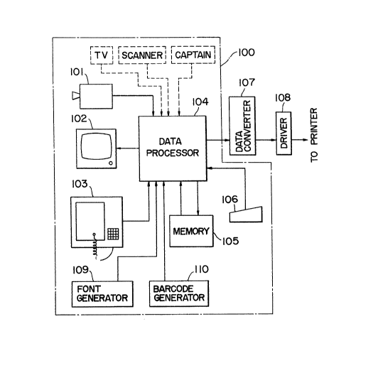
Firstr in Fig. lA, numeral 101 represents an image input
means which is adapted for forming image data based upon
optical and the like inputs delivered from a TV-camera,
line sensor or the like. Other than those above enlisted
only by way of example, video; CD; TV; scanner; personal
computer, captain system, capable of providing R.G.B.-
and picture image and the like signals may also be
utilized in a similar way. The image signal data
delivered from the image input means are fed through a
data processor 104 to a memory 105 for being stored
therein. These stored data can be taken out from the
memory and fed through data processor 104 to display
means 102 for being displayed thereat.
lS~ To the data processer 104, a mouth/tablet digitizer
and/or the like position data processer 103 is
electrically connected for~ introducing position data
;concernlng displayed~images appearing at the display 102.
In~addition, key~board and the like character data input
méans~ lQ6 ~and font generator 109 are provided for
ntroducing character ~data. Still further, a barcode
generator 110 is provided for introducing barcode when
; necessary. By the use of these means and units, various
additional processing modes can be executed.
25~ The~thus pr~ocessed data ~are subjected to conversion
at a data converter 107 into proper data adapted for
,~;,,, ;~: :
~` `.. '.''., ,`',"~
1 3 3 2 1 8 2
operating a sublimation transfer printer and fed forward
through a driver 108 to the thermal head.
In this case, by controlling the current duration
period to the thermal element of the thermal head, the
transfer quantity from the dyestuff film (thermal
transfer sheet) is controlled depending upon the thermal
.
energy of the element for realization of the desired
gradation degree of concentration on the transfer sheet.
',, ~There are two different modes of such control of current
."~ , , ~
duration period as follows~
(a) A method for controlling the pulse l'ength -,~
corresponding to the picture element in the impressed
data to the thermal element of the thermal head or, more ~;
specificallyi a series data introduced as input to the
5~ shift register shown in~Fig. 6 and to be described more '-
speci~fically hereinafter. ~
b) A method for controlling the number of pulses of
th~e:~pulse serles~corres~ponding to the picture elements of
thè~data impre;ssed upon the thermal element in the ,'
~ ~th-~rmal~ hesd ~in~thls case, the~ pulse length being ,' ;
constant~
The deyres of gradation of the transfer,image can be,
controlled in the~above mentioned way by the regulation ~ '
of~ the current-conducting period depending upon the
5, ~desired gradstion degree.~ On the~other hand, the image
concentration can be controlled by adjusting the pulse
length or the number of pulses contained in the pulse
~': ', ~
~ ~ .
,,,.. : :
t 332 1 82
series in correspondence to the picture elements
contained in the data as introduced in the shift register
and depending upon the driving mode of the thermal head.
Further in this case, if the number of gradation of
introduced image data is larger than that which can be
expressed by the printer unit, a proper conversion
operation can be performed by the known strobe control
:
method. As an example, in such case, the conversion of
gradation number 256 to 64 may be executed by a ROM, and ;
;10 the thus reduced gradation number can be used as output.
. . .
Next, referring to Fig. lB at (a) and (b), reference
numeral 121 represents a thermal head which receives ~
~; signals from the driver 108 shown in Fig. lA. This ~h
thermal head 121 is arranged in opposition to platen roll
122, forming the printing position therebetween. The
dyestuff film (thermal transfer sheet) is fed from a
.~ . . .
delivery roll 123 to a winding roll 124 through this -~
printing position, these structural and functional
features being commonly employed in both the arrangements
showll in Fig. lB at ~a) and (b).
In the case of Fig. lB, (a), the mechanism is so
arranged that card or sheet style transfer sheets are
printed with dyestuff images.
On the other hand, in the case of Fig. lB, (b), the vi
2~ mechanism is so arranged that cards are continuously -
produced with the use of a film style transfer sheet and
a dyestuff film in combination.
~,: ~ . , ,: .
:. ,, :,
-12- ;i
': ::, :
..:,.
1 3 3 2 1 8 2
: . -
Now turning back to Fig. lB, (a), a number of
transfer sheets (cards, sheets or the like) have been
stacked and stored within a storage casing 125 and are
being thrust upward from below by a spring so that the
uppermost sheet is kept in pressure contact with a take-
out roll 126. With the rotation of the roll 126, the
sheets are` successively delivered from the casing 125 by
conveyer belts 127, 128 onto a platen roll 122. Each one
of the sheets is fixed on the peripheral surface of the
platen roll, now positionally indexed, by means of a
gripper or the like mechanical attaching and separating
~; means, static attracting means, or electromagnetic
attaching means. Then, the roll 122 is so rotated that
:: the transfer sheet is positioned at the ready-for-
printing-position.
: Next, the thermal head 121 is brought into pressure
contact with the transfer sheet through- the intermediary
of:~the dyestuf film, and then the thermal head 121 is
energized with electric current while the dyestuff film
20~ and ~platen roll ~122 are moved in synchronism ~for the
~ execution of image transfer ~first image transfer).
`.": Upon execution of the image transfer, the platen
: roll 122 ls rotated, the gripper is released and the
take-out roll 129 ~s rotated and brought into pressure
25~ contact for taking out the image transfer sheet onto a
tray 130.
.~.
ii -13- ~
: . ,
~., ,, ', , , ".!.
-- t ~ 3 2 1 8 2 ; ~
The thus taken-out sheet is brought into overlapped
state with a new image transfer sheet, not shown, and
then, both the sheets are fusingly united together by
pressure application of a heated roll, not shown, for
execution of a second transfer step job. The whole
operation has thus been completed. Before the rusion
process, the sheets may be subjected to punching,
trimming and/or the like processing, if necessary.
By execution of the foregoing operational steps, a
monocolor printing operation has been completed.
However, in the case of multicolor print;.ng, use is made
of tricolored or quadruple colored dyestuff film and the
corresponding printing operations must be repeated. In
this case, upon completion of a single monocolor printing
5~ procedure, the platen roll is rotated without contact of
the~take-out roll 129,~until it arrives again at the
printing-1nitlation position, and so on.
In the following, a tricolor printing job~will be
ustrat~ed;with; reference to Fig. lB, (b), and;with use
of three differeAt s;er~ies color zones, of ~cyan,~m-genta
First, a platen ~roll 122 is positionally indexed,
and an image transfer sheet taken out from the roll 131
6nd~ a~-dyestuEf `film~taken out from the roll-~123 are
25~ brought; into~ pre~ssure ;oontact in an overlapped st~ate.
Then~ a the~rmal head l21 is pressed againat the platen
rol 1 122 through the intermediary of the overlapped
r~;
1 332 ~ 82
sheets. At this stage, the platen roll 122 is rotated
counterclockwise while synchronism is kept between the
platen roll 122 and the dyestuff film, and the thermal
head 121 is kept electrically energized. In this way,
the first color printing is executed.
Further, the dyestuff film is fed to the second
color zone position, and then, the platen roll 122, the
dyestuff film and the image transfer sheet are fed
forward clockwise around the center roll 122. Thus a
second color printing step is executed.
Further, the print-serviced two color sections of
the film is fed back counter clockwise around the center
of the platen roll 122 for the execution of a third color
`~ printing step. Then, each card sheet is taken out from
~ lS the stack 200 under the action of take-out rolls or the
:, .. . :, .,
; like, not shown, towards and between a pair of thermal ;
transfer rolls 132, 133, brought into overlapping state
r~
~ With the image tran~fer sheet positionally indexed and
P~ already subjected to image transfer steps as was
20~ described above,~ and finally subjected to a picture
printing operation by pressurizing application of the
thermal image transfer rolls 132, 133 from both sides of
each taken-out card, and so on.
The color-printing step With the use of the thermal
head~is carried into effect in the following manner, as
an example.
(First color printing)
-
.
-15- ;~
t 332 1 8~
Platen roll, image transfer sheet and dyestufE film
perform the printing while they are moved in the
counterclockwise direction.
(Second color printing)
Platen roll and image transfer sheet are moved in
the clockwise direction while the dyestuff film is moved
at the same speed and in the counterclockwise direction
for performing the color printing under consideration.
(Third color printing) ;
Platen roll, image transfer sheet and dyestuff film
are moved in the counterclockwise direction for exe~ution ~
~ of the color printing under consideration. ~ `
-~ In the modified arrangement shown in Fig. lB, (c),
thermal image transfer rolls 132, 133 have been replaced ~
by a flat press type image transfer head having up-and-'A~''~''~''
~down movable flat printer elements 132', 133'. ` ;
It should be noted that in the course of the
foregoing first and second image transfer steps, image `~
reversal phenomenon is necessarily brought about upon
execution of each image transfer step. In other words
and more specifically, when two successive image trans~er
steps in the foregoing sense are executed, reverse images
which have once appeared will return to the original
.~.
normal images. Therefore, when the printed-out products
2~ are to be provided upon execution of the first image
transEer step, it is necessary to provide reversed image
~ data in the signal porocessing system. For this purpose,
,.':~ '
-16-
- ':, .'
--- 1 3~2 1 82
it is only necessary to reverse the addressing order at
the data introduction or readout stage into or from the
memory.
In the modified arrangement shown in Fig. lC, the
foregoing platen roll means has been replaced by a metal
block 141 lined with a rubber plate 142 in an overlapped
manner. The image transfer sheet and dyestuff film are
fed out from respective rolls 131 and 123. With the use
of this modified arrangement, the dyestuff surface layer
of the dyestuff film can be brought into tight contact
with the image-receiving surface layer of the image
transfer sheet, and thermal energy will be transferred
evenly form the thermal head 121 to the dyestuff film.
In this case, the image transfer sheet is delivered
from the roll 131, and the desired zone or region of the
sheet is set underneath the rubber plate 142 (step 1).
At the same time, the dyestuff film shown in Fig. lD
on an~enlarged scale is delivered from the roll 123 and a
se1ected~one of~the different color regions is set
20~ underneath the rubber plate 142 (step 2).
Next,~ the~thermal~head 121 is brought into the rear
-~ ~ surface of the dyes~tuff film which is the opposite
surface to the dyestuff-coated front layer, and the head
121~ is~ driven whl~le it is being translated in the
5 ~ dir~ect~ion; shown by~an arrow A, images thereby being
formed at the specifically allocated zone(s) or region(s)
~; of the image transfer sheet (step 3).
17-
~ ~ ' '.',~ ,,'
` ~ 1 3 3 2 1 ~, 2
Further, the thermal head 121 and rolls 416 and 418
are shifted downwards as shown by arrows B, so as to form
an idle gap between the image transfer sheet and the
dyestuff film for allowing the latter to shift towards
the next following color region (step 4).
Further, the thermal head 121 and rolls 416 and 418
are returned to their original positions, whereupon the
third and further succeeding steps are repeatedly
executed until a certain predesired number of color
printings are completed.
As shown in Fig. lD, the dyestuff film is colored to
have several different color regions denoted by Y
(yellow), M (magenta), C (cyan) and Bk (black). However,
` the arrangement order is not limited to that shown: Y; M;
~::
C and Bk. In addition, as occasionally required, the Bk-
region may be dispensed with. Further, as the color
elements to be adopted in the Y, M, C-system may not be
limited to the three primary colors provided by the
subtractive color mixture. On occasion, a characterizing
20~ color Which means such a color as preadjusted to provide
an objective speclfically selected one may be used to
form the images concerned. As a further modif~cation,
the arrangement shown in Fig. lC may be so modified that
the traveling direction of the image transfer sheet is
selected to be perpendicular to that of the dyestuff
~: .
~ film.
" "~; ~'
~ -18-
~ ~33~1~2
Fig. 2 is an operation flow chart for showing
schematically operational modes taking the data processor
104 adopted in the embodiment shown in Fig. 1 as the
centrum of description. The operational contents of
several working parts downstream of the data converter
107 will be set forth separately hereinbelow. Now
referring to Fig. 2, in combination with Fig. 1 and at
the step of S101, image pickup operation is carried out
by means of the image pickup means 101. For execution of
this step, it may be better to pick up the face of a
person per se which is to be represented on the card, or
alternatively, a photograph, portrait or imagery product
thereof will do. Depending upon the nature of the object,
a TV camera, line sensor or the like instrument may
naturally be selectively utilized.
The data taken by the image pickup means 101 are
" ~ :
stored through the data processor 104 at a memory 105
5102). By the use of these stored data, image or images
, ,c . ~
is/are displayed at the display 102 (S103). Since this
20~ display image is not yet subjected to any processing, it
is~ g~enerally unsuitable for representing on the card.
~` However, under certain circumstances, it may be
represented thereon as it is.
Then, the operator observed the displayed image or
Z6~ images on~ the display unit 102 and adjudges whether
additional processing is necessary or not (S104). If it
is not necessary, he will manipulate the key board 106 to
19
: ` 1 3 3 2 1 8 2
make a certain operation, resulting in the termination of
processing at the data processing unit 104, data being
fed out therefrom to the succeeding data converter 107.
On the contrary, when additional processing is
5 necessary, the operator observes carefully the displayed
image or images on the unit 102 and adjudges whether the
picture image data, or character data or barcode data
should be processed. If the picture image data should be
processed, such an operation is made for selecting the
10 proper mass of trimming or layout within the menu range
of position-data input means 103. By the execution of
this operation, functions and operations at steps S105
, ~
and S106 can be executed at one stroke. If trimming is
taken as an example, the next step is executed in such a
15 way that position data are fed from the position input
f means 103 to the data-processer 104 with the use of a
carsor. When a tablet digitizer is used as the position
data input means, the carsor image displayed in an
overlapped~ manne~r on the displayed picture image
2o~ appearinq~at the dispIay unit 102 by carsor manipulation
is~positionally specified beforehand in registration with
the specified position on the card, for determining the
trimming range. Then the operation is carried out in
such~a way that the picture image data outside the
25 ~ ~ specified trimming range are canceled. By completing
these operations, data processing operations relating to
step 107 are executed, and, then, the mass for completion
-20-
~ , ' '~ '
~` 13321g2
oE the menu range is selected out. By these measures,
steps progress through S109 to S102, and data storing is
executed, and further, display representation is brought
about through step S103. If there is no need for
additional processing, an operation termination
manipulation is carried out as before at key board 106,
and further operations will be made through data
converter 107.
As for the layout, the operation is carried out with
the position data input means 103, similarly as in the
foregoing trimming operation. More specifically, layout
is selected out in the menu range of position data input
~`~ means 103, and the overall configuration of the card and
the display position of picture image are shown at
5~ ~ display unit 102. Then, image inclination correcting
operation and the like are carried out so as to realize
correspondence thereo with the displayed positional
information, the processing operations relating to step
S108~thereby being brought about. After completion of
~th~ese~operations, the~mass for the ending in the menu
range~ lS ~selected.
; In this way, when selection is made from the menu
range by reliance on the position data input means 103,
tr`imming or layout operation can be brought about. At
this~stage, when manual operation is carried out at the
key~board~106, lntroduction of character data is executed
(S110~. As the character data in this sense, in the case
-21-
1 332 1 82
of ID card, as an example, the name and/or birthday,
month and year of the owner may be used. The data
introduced from the key board 106 in accordance with the
output character style from the font generator 109 are
shown at the display unit 102 in the specified positions
on the displaying surface and respectively arranged in
accordance with display items. The operator acknowledges
these items and detailed displays of the represented
images. When he acknowledges them as being true, he will
operate the key board 106 for showing the operation
ending (Slll).
Upon ending the operations as described above, the
~; data are stored in memory 105 (S102) and represented at
the display 102. The operator will acknowledge again
this fact, and upon the execution of this, the operations
are terminated.
As for the barcode introduction, the data are
subjected to inputing at steps S112 and S113, as in a
manner similar to the character data introduction as set
~forth above. The barcodes and the like data may be
ntroduced separately through printing or other
mechanical method.
In Fig. 3A, a data processing circuitry usable in
the sublimation image transfer printing method is shown
only schematically. As shown, the circuitry 107
comprises a picture element density converter 3; a color
corrector 4; a gradation corrector 10; a memory 11; a
.~;
-~ -22-
~` ,;
~ ,:
3 3 2 1 8 2
switch 12; a buffer 13 and parallel/series converter 14.
The picture element density converter 3 is connected to a
picture image input unit 100.
The unit 100 serves for generation of three primary
color data of R.G.B.- or Y.M.C.-mode from original
picture images and is connected through the picture
element density converter 3 to the color corrector 4.
The converter 3 conv2rts the picture element density of
the image data fed from the unit 100 to the desired one,
~i 10 by subtracting or supplementing, as the case may be,
- .~:~ -,:. - .
image data for each color element. It should be ;~
mentioned that for attaining high quality hard copies,
conversion of the picture element density to at least 10
lines/mm or so is preferable. -
15 ~ Color corrector 4 consists preferably of a color ~;
decoder, level adjuster or color converter, and serves to
correct~three primary color data converted to those of a
p~rede~termined den~sity of picture elements in ~`
ccn~sideraticn of characteristics of the image transfer ~-~
ink~in ~the image~ transfer sheet and in addition to ;~
prov~ide~black~color~data.
The data processing circuitry 107 is connected
through; a driver 108 to the sublimation image transfer ;-
pr~i~nter.
25 ~ ~ In~Fig. 4, an example of the color corrector 4 is ~
shown schematically in structure. As shown, it comprises ~ j`
adders~`~6Y; 6M and 6C, a black color data calculator 7, --
23~
`"- ! 3321 82 `
and primary and secondary color correction circuits 8 and
9. Primary color correction circuit 8 serves for making
correction of turbidity of the image transfer ink, while
secondary color correction circuit 9 provides a
capability of arbitrary and selective correction control
relative to speciEically selected color hue.
The gradation corrector 10 is so arranged as to make
correction of the gradation of the data for each color Y,
M, C or K (representing black color) fed from the
foregoing color corrector 4 when necessary. For this
purpose, the corrector 10 includes a gradation circuit
(not shown) and the like, whereby a certain mode of i~
highlight stressing or shadow stressing is introduced and
realized.
15~The memory 11 functions to preserve temporarily the
data of each color delivered Erom the gradation corrector
lOr a selection ~switch 12 being provided at the output
side o the memory for selective writing-in of the data ;~
oE each color to the buffer 13. The buffer 13 is
capable Oe wr~iting-in the data of one line of the image
transfer~ head~ 16 and kept in connection with the
parallel/series converter 14 adapted for converting
parallel data into series data. Additionally, in the
simplified machine, black color data series is dispensed
25 ~ with~ in some instances. ~ ~-
In Fig. 5, a schematic construction o~f the ~ ~
, j . ., ~ ~
parallel/serles converter 14 is shown. As shown,
24
3~2
parallel data delivered from the buffer 13 are fed to an
input side of a comparator 22, while outputs from a
counter 23 are fed to another input side of the
comparator 22 which delivers the converted series data to
the driver 15 for driving a thermal head 121.
If necessary, however, the comparator 22 may be
replaced by a converter table, not shown, utilizing a
parallel/series converting ROM.
In Fig. 6, a detailed circuit schema of the ther~al
head 121 is shown. As shown, series data delivered from
the comparator 22 are fed into a shift register SR and
thence, after being subjected to latching at a latch
circuit LT, fed to thermal elements HE through NAND gates
NA which are fed at respective one side inlets with
15~ strobe signals.
Next, referring to Fig. 3A, the operation of the
;data~ p~rocessing circuitry 107 will be described more
specifically.
First,~ when three pr~imary color image data are fed
from ~the picture lmage inlet circuit 100 to the -picture
element~density converter 3, the latter converts these
three primary color data to those which represent a
;predetermined picture element density and then are fed to
the~color correction unit 4. In this case, it is assumed
~;~that~the unit 4 is fed with three primary color data
expressed in respective concentration signals, which are
25-
j ! ', ~ : '
-- ~ t 3~2 1 82 ;
, .
of yellow: Y0; of magenta: M0 and of cyan: C0,
respectively, in the present example.
These data: Y0; M0 and C0 are, as shown in Fig. 4,
fed throu~h respective adders 6Y; 6M and 6C to the black
color data calculator 7, to provide a K-output as
expressed mathematically by the following formula:
:,
K = min (Y, M, C)
10 wherein, "min" represents a function which provides a ;~
possible minimum value.
These data: Y0, M0 and C0 are fed from the converter
3 to the primary color correction circuit 8 to provide
prlmarily corrected data Yl, Ml and Cl which are thence
15 ~j fed to the secondary color correction circuit 9 to
provide, through calculation, secondarily corrected data: t
Y2, ~M2 and C2, respectively. These are then fed to -~
respective~adders 6Y, 6M abd 6C, which add them to
re~spective :data YO~, ~MO~and C0, to provide respectively
20~ added~output~data~Y, M, and C to be fed to the gradation
correcter~ circuit lO,;;~respectively, after being utilized
for calculation Oe the K-output signal value.
The primary color correction circuit 8 serves to
calculate~primarily~oorrected data: Yl, Ml and Cl which
5; ~are~necessarily~ utilized for~oorrect-out of transfer ink
~ turbit. ~In~ this case, the original data: Y0, M0 and C0
$~
-26-
., ::
: . .
- 1 3 3 2 1 ~ Z ! : ~ :
are subjected to matrix calculation to provide the
primarily corrected data Yl, Ml and Cl, as folows~
Yl = kll C0 ~ kl2 M0 + kl3
Ml = k21 C0 + k22 ~ M0 - k23 Y0
Cl = k31 C0 + k32 M0 - k33 u yo . .
where, kij represents weight coefficients: `~:
; i = 1 - 3; and
1 0
The secondary color correction circuit 9 serves to :~
calculate secondary color correction data Y2, M2 and C2 ,-
from primary color correction data Yl, Ml and Cl by
modifying the latter to make certain thereto by . .`.`~
~ performing~ matrix calculations so as to~ provide a
capability~ for making an ~arbitral and selective color
contr~ol~at~a~certain spe~cifically selected-out color hue, ` ~?~ "~
in~:the~following manner~
2`0~ Y2~= Y1 +~e~ B + el2 ~ aC + 413
aG ~-t:~ el4 - ~y + el5 ~R + el6
M2 - Ml + e21 ' ~ aB + e22 ~C e23 ! ~ ` .` . -` .
aG + e24 ~ ~Y~+ e25 ~ aR + e26 aM~ and
C2 =~Cl + ~e3~ B~+:~e32 ~C + e33 ~ .` ~`-
25~ ; aG + e34:; ~Y:+ e35 ~ R + e36 aM ;~
:wh~rein, eij represents weight coefficients~
: `i = 1 - 3;
l ~
: ~: 27 ,:
1 332 1 82
.. .
':.';. ! ' ~
j = 1 - 6;
~B, ~C, ~G, ~Y, ~R, ~M:
characterizing color data.
Thus, when these secondary correction data Y2, M2
and C2 are added to the corresponding original data YO, -~
MO and CO by means of respective adders 6Y, 6M and 6C and
- under proper selection of weight coefficients kij for
primary color correction circuit 8, any color discrepancy
,,
of the ideal color of the ink appearing on the printed
,;
~;~ picture images under the action of the sublimation
transfer printer can be arbitrarily ammended. In this
case~ when the weight coefficients ei j for the secondary
oorr~ection circuit 9 are selected out properly, the color
5~ tone: of the printing~picture images~can be modified to an
ar~bitra~ry degree.
Fùr~her~, as for the~black color data K, correction
data~K2~can~be~c~lLul~ted~by~the ollowing formula. With
Us~e~of;~these;~correction data K2,~which are added to the
iginal~black~color~dàta~K, the~ desired oorrection can
be~ exe;cuted~ in a~ similar manner.
K2. = K + ml ~B ~ m2 ~C ~ m3 ~G + m4
Y~ m5 ~ ~R ;~:: m6 ~M
5~ wherein,~mi~r~epr~esents~ weight ~coeff icients~
28-
i~ : . :,'
- ~ 1 s32 1 82 :: ~
In this way, output data: Y, M, C and K delivered
from the color correction circuit 4 are introduced into
the gradation corrector 10 as inputs thereof, and each
constituent of these data can be subjected to correction
as desired.
Fig. 7 shows several characteristic curves
illustrating corrections by means of the gradation
corrector 10. More specifically, fO represents a
standard characteristic curve; fl a highlight-stressing
operation curve; f2 a shadow-stressing operation curve;
f3 a highlight-and-shadow stressing operation curve; and
f4 a medium tone stressing operation curve.
As indicated in Fig. 7, by presetting, as necessary,
the tone-reproducing characteristics, which determine the
~relationship between that concentration of color data and
that~ Oe the prints printed by means of a sublimation
image transferring printer, a color tone similar to that
pos~s~essed by~ the original image can be reproduced. More
speeifically, when no~correction is adopted, the curve fO
s~ùsed, while~ln the case of correction, any selected
one~oE these curves fl~to f4 may be utilized depending
; upon the part of gradation to be stressed. Further, it
should be noted that the tone reproducing characteristic
cur;ves are not exclusively limited to those which have
5 ~ ~been specifically shown and described above. As an
example, ~the control of gradation correction by color
tone reproducing characteristic mentioned above is
29
,:
~: . ; ,.: , .
~2~82
. .
executed by a gradation circuit, not shown, and the
setting of the color tone reproducing characteristic is
brougnt about by manipulation of any selected one of the
control knobs, not shown, which are provided separately
for "highlight"; "medium tone" and "shadow".
Y.M.C.K.-data subjected to correction by the ~ ~-
gradation corrector 10 are once stored in the memory unit
11. The thus stored data may be read out from the memory
for each color by manipulation of the selection switch 12
and, after provisional storing, per one line of transfer
head 16, at the buffer 13, introduced into the
paralleltseries converter 14 for conversion thereby into
corresponding series data.
~; Another example o~ the data processing circuit for
the subllmation transfer printer is shown only
; ~ - schematically in Fig. 3B. As shown, the processing
circuit in 107' comprises a level regulator 503; a color
converter 504: an A/D converter 505 and a parallel/series
converter~l4.
~ ~As the image data introduced into the processing
circu~it 107', those which have been subjected to . ;
conversion into R.G.B.-signals in the color decoder 502
from composite video signals delivered from a T.V.
camera, VTR ~or the like are used. On the other hand,
R~G.B.-signals delivered from a personal computer,
captain System or the like means are introduced as input
into the level adjuster 503.
30~ ~
~ .
~ ~` 1 332 1 82
; ,,," " ;; ,
As the color correction method with the use of the
foregoing arrangements, it is possible, more
specifically, to adjust the hue saturation and/or
brightness in the color decoder 502, or to adjust the
signal level of each color light of R.G.B.-system in the
level regulator 503.
As an example, the color conversion from R.G.B.- to
Y.M.C.-system can be executed in the color converter 504.
The simplest possible method in this color conversion is
to procure the opposite color to each of the normal
colors.
The thus produced color signals of Y.M.C.-system is
; subjected to A/D conversion and then fed successively
through the parallel/series converter 14 and the driver
S ~108 ~to the thermal~ head, not shown, to carry out
;printi~ng in the sublimation transfer principle.
Addltionally,~ ln normal cases, with the use of the
for~egoi;ng system composition, input image data must be of
stat1c mode. However, by provision of memory means in
20~ E}ont~ of~;the color~decoder or at an intermediate position
bet_ en ;the~A/O converter~and parallel/series converter,
anlmating images can be processed.
The aeriés data converted in the foregoing manner in
the~data con~verter ~107 or 107' are fed to the shift
25~; register sR~shown in Fig. 6 by n-image elements~and then,
upon being subjected to latching in the latch circuit LT
are further delivered to NAND gate~ NA as its inputs.
-31-
~332182 : ~
When a strobe signal ST is fed as input to the NAND gate
NA, the foregoing n-image element data is fed ~o the
thermal element HE.
Fig. 8 is a schematic diagram, showing signals for
S respective image elements. The gradation has been so
selected that the first image element is at the highest
gradation level, while the n-th image element corresponds
to the lowest gradation level, and that the second to (n-
l)th image elements vary linearly in gradation levels, so
as to provide representatively a better understandable
example of the invention.
Next, the operation of the parallel/series converter
14 will be described.
First, as shown in Fig. 5, image elements data A,
consisting of parallel data, more specifically,
i~comprising parallel eight bit data A0 - A7, are fed to
cne-side inputs of comparator 22, while another side
inputs thereof are fed with outputs B, comprising eight
b1t increment outputs B0 - B7, of counter 23. The
~counter 23 counts clock signals in increments, the
;, . ;; ~ ~ -
outputs B0~- B7 being successively varied.
;The comparator 22 performs comparison between the
two inputs A and B, so as to deliver successively outputs
of~binary "1" until the increment output B is brought
2i5 ~into coincidence with image elements data A, or more
speciically, under the condition of A>B~and A=B, while,
thereafter, binary "0"-outputs are delivered therefrom.
.~, ~ . .
~ 32
; ~ A ;, ", . ,;; .
~32182
More specifically, comparator 22 will continue to deliver
binary "1" until an increment value which corresponds to
the weight of concentration of image element data A is
given thereto. As an example, if the image element data
:., :. :.
A has a concentration of gradation 128 of a total 256,
output "1" will be repeated to deliver 128 times first
and then, output "0" will follow after again 128 times,
so as to provide in total a specific series data
peculiarly in this case.
These series data are taken out from the comparator
22 in the form of A>B- and A>B-outputs and of A = B-
outputs through an attributed OR-gate 24, and in the
present example, the gradation consists of 256 steps or
-~ ~ increments. However, in practice, the gradation may
represent a smaller number of steps. As an example, if
the incrementing bit is Bl instead of hitherto employed
B0, the gradation will have 128 steps; and if B2 is
employed, it will have only 64 steps. In this way, the
gradation setting may be varied in a simple manner.
20 ~ When in the foregoing way, the output B from the
counter 23 is stepwise incremented, such series data
~ i consisting of a first series of "1" will be delivered
- ~ until the relationship between the image elements data A
and the output B from counter 23 becomes A = B, and of a
second series of "0" issued thereafter, as shown in Fig.
- ; 8.
J' ~
~ 33- ~
~ r
t332182
In Fig. 9, a conversion mode at the parallel/series
converter 14, which, however, is different from that
shown in Fig. 8, as an example, is shown again in the
form of a matrix. As shown, when the image data are of
8-bit parallel kind, as an example, the gradation data
are ranged from O to 255, providing, therefore, binary
series data from "00 ...... 00" to "11 ...... 11".
In this way, the data, per line in the transfer head
16, kept preserved in the buffer 13 are fed to the
; 10 parallel/series converter 14 for providing as outputs
therefrom into corresponding series data which are then
delivered through the driver 15 to the transfer head 16
~`and thus recorded on a print paper P supported on the
,~:
transfer drum 17.
Fig. 10 represents a flow chart illustrating the
` ~ ; operation of the sublimate printer as employed in the
present invention.
; At the first step Sl, print papers are set in
pos~ltion and the prlnting ribbon is also set in position
ready for performing~the required procedure.
At the second step S2, printing operation is
initiated, and line printings are executed, line by line,
accompanying necessary intermitte`nt line shifts, !with
relation to any selected one of four colors: C (cyan); M
(magenta); Y ~yellow) and K ~black) being carried out.
Ree~r ~to S3 and S4. When line printings wlth the
selected-out single color have been completed ~S5), the
`~ ~34~
.
: .
1332182 :
';" :.
image transfer sheet is replaced by another color sheet
(S6) and so on. In this way, line printings are
completed in all four colorsr In this case, it is ~-
naturally most preferable to use a long extended single
5 transfer sheet on which four color ink regions are --~
repe~tedly printed in a certain predetermined pattern. ::
The image reception paper is initiated to make print from
. - , .: :.
a certain prescribed position for each of these colors
(S8). When all of the printing steps have been completed
with the four colors, the paper is discharged from
position (S9) and the printing operation is terminated to
be repeated.
In Fig. ll, a card style sample of the final
products according to this invention is shown in front
15view at 200. Fig. 12 is a sectional view thereof.
Numeral 201 represents the substrate material of the
card; 20~ a display layer; 203 a surface protecting
layer; and 204 a display image as an example. Depending
upon the kind of usage and when necessary, the protecting
layer 203 may be dispensed with. It should be noted that
the display image 204 on the display layer 202 is
. ~ ~
; ~ represented by a sublimative dyestuff, as a - -
characterizing feature of the present invention.
~ As the main and substantial material of the image
`~;25 transfer sheet, various plain papers, converted papers,
,
c~plastic resin sheets or the like may be used Per se or in
~ .
combination. When a plastic resin sheet which can be
;
~35~
1 3 3 2 1 8 2
colored directly with a sublimative dye or dyes is used,
these image transfer substrates (articles or objects) as
a. 201 can be united each with the display layer 202.
Each of these substrate materials, when it is of the card
style, may have generally such dimensions: thickness of
0.68 to 0.80 mm and size: ll to 8 x 8 to 5 cm.
As the material of the display layer 202, various
known materials which may be colored with sublimative
; dyestuffs, such as polyethylene, polypropylene,
polyester, ABS, AS, polyvinylchloride, polyvinyl/vinyl
acetate copolymer, polystyrene, polyacrylate, polyester,
polyamide, pulyurethane and the like plastic material,
may be advantageously utilized. As will be more
specifically described hereinafter, this material layer
15 ~ can be united with the~substrate material layer 201. In
the case of such unified structure with substrate layer
201,~ the thickness and size dimensions may be
substantially as ~the sams as before. However, when
~ normal ;and/or converted papers or metals, which are
k ~ 20~ p~rscti~cal1y ~impossible to color with sublimative
dy99tuef9l ~are ussd ag the substrate layer 201, various
methods can be utilized for desired coloring. As an
example,~a solution including at least any selected one
of~ plastic resin~ materials capable of coloring with
25~ sublimative ~dyestuffs may be coated on the substrate
surfacs, or~ alternatively used in the form of a film
which i9 laminated thereon. This kind of film preferably
36-
~ 332 ~ 82
~......
has à thickness of about 3 to 50 ~m or so. One of main
characterizing features represented in and by the final
products 200 is that the appearing display image or
images as at 204 is/are formed at least partially or
wholly with a sublimative dyestuff or dyestuffs.
Additionally, the process for formation of such images
can be executed in the conventional art.
As an example, the processing method may be executed
conventionally as follows.
10As an example, a sublimative image transferable
sheet, such as a pa~er sheet, plastic resin film or sheet
capable of acting as the carrier is coated on its surface
with any suitable binder resin carrier carrying
~; sublimative a dyestuff or dyestuffs under heat, is
: , .
~ 15 overlapped on the display layer 202 and then subjected to
~ .
heat from behind the heat-transferable sheet, preferably
in the pattern mode, so as to transfer the dyestuff or
dyestuffs into the display layer 202. It is proper to
select the molecular weight of 250 or larger of the
~ dyestuff, for improving the fastness thereof. However, a
molecular weight higher than 370 is more favorable. In
the case of provision of the surface protecting layer,
there is practically no limitation to the selectability
~ . ~
of the dyestuff molecular weight.
The sublimative image transfer may be executed
directly on the surface of substrate 201 provided with
,-
~ the display layer 202. Or alternatively, a ca~rrying, -~
'`' ~
~37~ ;~
:,
image transferable sheet is prepared separately and,
after formation of the image 204 thereon, may be stuck
onto or laminated on the substrate 201.
Imaqe-carryinq and imaqe-transferable sheet
In the following, structure, material, usage and
application purpose of the image-transferable sheet to be
employed in the present invention will be described in
detail~
Fig. 13 illustrates only basically and in schematic
sectional view the image-transferable sheet adopted in
the present invention, while Figs. 14 through 19 and 22
through 24 illustrate preferable embodiments thereof.
!.. : ~ ' . -' :
The basic structure of the image transferable sheet
310 is characterized in that, as shown in Fig. 13, a
~sheet-like substrate 301 is provided at its one surface
with an image-reception layer 302 capable of peel-off
from the substrate. By adopting such a structural
; conf~1guratlon of the image-transferable sheet, the image-
reaeption layer 302 can be ormed with the required image
or ~images ~with~ the use of an image transferable sheet
having thermally~shiftable dyestuff, and then, the image-
formed, image-r~eception layer 302 is peeled off from
substrate 301 and attached firmly, preferably as by
sticking, on the surace of any selected object or
25~ artic~le~ with use of any suitable means. In this way,
various convention~al drawbacks inherent in the
-38-
- t332182
comparative conventional technique can be basically
overcome.
More specifically, as the material of the
aforementioned image-reception layer 302, limitation must
be imposed to those which can be colored with thermally
shiftable or transferable dyestuff. ~owever, upon
formation of necessary images and upon peel-off from the
sheet-like substrate 301, the image-reception layer 302
may be attached fixedly onto the surface of glass-made,
metal-made or wooden-made products or plastic-resin made
ones which are very difficult to color with thermally
shiftable and transferable dyestuffs, indeed, by reliance
on conventional sticking techniques as properly adopted
in consideration of the specific nature and kind of the
lS material of decorative products to be ornamented.
:,
Further, the image-formed and peeled-off, image-reception
layer 302 from the sheet substrate 301, is highly thin
and thus sufficiently pliable so~that it may be applied
even onto any uneven and complicated surace of a product
to~ be decorated or ornamented, having undulations,
convexities, concavities, recesses and projections.
Therefore, a maximum possible better fitness of the
" k ~ image-reception layer to be ornamented is attained and
guaranteed by the~present invention. Thus, practically
~;~; 25 ~ no limitation in the attaching use thereof may be
encountered. Further, in sharp contrast to conventional
sealing seals and the like, the very thin image-reception
-39-
7 332 1 82
layer bearing necessary images can be applied easily to
the product per se in a very uniform manner, thus
providing no raised and thickened feeling, and giving
rise to no foreign feeling upon attachment.
Fig. 14 shows a further example of the image
transferable sheet 310. In this case, there is provided
a partiny agent layer 303 on the surface Oe image-
reception layer 302. Between the latter and the sheet
substrate 301, there is provided a parting agent layer
303'. If necessary, however, any one of the two layers
303; 303' may be dispensed with.
The first parting agent layer 303 is provided for
prevention of thermal fusion between the image-reception
layer 302 and an image transferable shee;t, not shown, as
S~ may~ occur during image transfer and formation on the
fi~rs~t ~layer~ 302 through transfer ~ of thermally
;transferable dyestuff~from the said transferable sheet to
the~ eirs~t~;layer. ~If there is no risk of such thermal
us~lon ;of the ~above;~ nature, ; or when the image-
0~ ;transferable sheet has b~een already provided with such a`parting agent~layer~the present provision thereof may be
unnecessary. As for another parting agent layer 303', it
is~ Eor~ the purpose of making the latter peel-off
- ~ ` operatlon~,~ to~ be~ executed after ~image-forming ~step,
2b ~ easier~ When t~he ~sheet-like subgtrate 301 ig~ made~o
polyeste~or t~he lik~e material which has, as it is,
suffioient separability from image-reception layer 3~02,
~-
~ ` - t 3 3 2 1 8 2 . -~
provision of parting agent layer may naturally be
dispensed with.
Fig. 15 illustrates a still further example of image
transferable sheet 310. In this case, between the image-
S reception 302 and the sheet-like substrate 301, an
intermediate layer 304 and/or parting agent layer 303'
is!are provided. The laminating order is optional and
thus not binding. The intermediate layer 304 will serve
to assist the image formation to be rather firm and
beautiful, the image formation being carried out by
transferring the thermally shifting and transferring
dyestuff from the image transfera~ble sheet to the image-
reception layer 302. For this purpose, the intermediate
layer 304 may take, for example, the form of a cushioning
lS~ layer~or heat insulating layer. When a cushioning layer
is provided as the intermediate layer 304, the 'cohesion
` ' ;'~- between the image ;transferabIe sheet and the image
recept~ion~layer ~30Z~is greatly improved and the thermal
shlft~and~tran~sfer~oE the dyestuf during image fcrmation
with~ the~use~o ~a ~th~rmal ;head ls evenly executed, the
'image~ formatlon~thereby being ~càrried out amply in
correspondence with the supplied image signals. Further,
when~a ~heat insulating layer consisting of a highly heat~
~J~ ` ' 'insulàt1ve~ma~t~erial is~used as the intermediate~layer~
5~ 304,~inefective release;of the heat applied durin~g shift
and ~trans~fer ;of the ~dyestuff from the image transferable
sheet to~the image-reoeption layer 302 can be reduced to
41
~ 3321 ~2 : ~
. ~ ~ .; .
, ...:
a minimum possible, the eEfective thermal efficiency
thereby being correspondingly improved and ample image
formation being accelerated. If necessary, however, ~ ;
these cushioning layer and heat-oinsulating layer can be ;~
prepared independently and arranged concurrently in any
arranging order.
Additionally, when the intermediate layer 304 is
arranged at a higher level than the parting agent layer
303', the intermediate layer 304 will be conjointedly
peeled off in the case of peel-o~f of the image-reception
layer 302. On the contrary, when the intermediate layer
304 is arranged at a lower level than the parting agent
layer 303', the intermediate layer will remain on the ~;
sheet-like substrate 301 aEter execution of the
separation of 1mage-reception layer 302. In this case,
therefore, the intermediate layer 304 may be made
prefer~ably and at least substantially transparent, when ~
the peeled-off image-reception layer 302 is stuck on a n-
;decorative product,~ wbile directing the surface of
~parting agent layer 303 towards the latter
In the modifications shown in Figs. 16, 17, and 18,
modified from the foregoing embodiment shown in Fig. 15,
. .
` ' ` a furtherl pfotecting layer 305 is provided between the
image-reception layer 302 and the sheet-like substrate ~ `
5 ~ 301. This protecting layer 305 serves to prevent ~1
deterioration of the formed images in the image-reception
layer 302 when the latter is stuck on the decorating
J~ "; ' ,; ~
-42~
. ; ., . ~ .
- ~ 332 1 82
product while directing the surface (more specifically
the image-formed surface) towards the product. For
eY.ample, this protecting layer 305 is prepared from a
superior material which exhibits at least one of desirous
properties such as antiwearing, light-fast, weather
proofing and anti-chemical qualities. With the use of
the protecting layer 305 having these superior qualities,
the images can represent improved fastness in the above
various aspects, even after execution of the foregoing
sticking procedure.
In the modification shown in Fig. 16, the protecting
layer 305 is arranged between the intermediate layer 304
~; and the parting agent layer 303'.
In the further modification shown in Fig. 17, the
protectlng layer 305 is arranged between the image-
reception layer 302 and the parting agent layer 303'.
In still another modification shown in Fig. 18, the
intermediate layer 304 takes the role of the protecting
layer 305.
20~ In each of these modifications, the protecting layer
305 is arranged in~ neighboring relationship with the
partition agent layer 303', whereby the image-formed and
re~motely arranged, image-reception layer 302, kept in its
up-and-down reversed state, is capable of adhering
; ~ 26 securely to the decorative product, so as to be
positioned as an uppermost layer, as may be required. In
a still further modification shown in Fig. 19, derived
~ 43
~ 3 3 2 1 8 ,~ ~ ~
from that shown in Fig. 1~, a sticking layer 306 is
further provided between the image-reception layer 302
and the partition agent layer 303. It should be noted,
however, that such a sticking layer as at 306 may be
5 provided in any one of other foregoing examples and B ;~
modifications, if necessary, in neighboring relationship
with the parting agent layer 303'.
-~ The provision of such a sticking layer as at 306 is
; highly valuable when the image-formed and peeled-off,
image-reception layer is adhering without position
reversal onto the decorative product. With this -~
. .
arrangement mode, the protecting layer 305 shown in Figs.
16, 17, and 18 may be dispensed with. If, however, the
protecting layer 305 is composed of a material in the
S~ form of a sheet-like substrate, the part to be peeled off
is thereby strengthed, the peel-of~ procedure thus being
gr~eatly facilitated.
By prev~oUs~provlsion of the sticking layer 306, the
image-formed and peeled-off, image-reception sheet 302
àan ~;be~caused to adhere as it is onto the decorative
product w1thout use~of a separate sticking agent. As the
; sticklng layer 306, an ordinary sticking agent which is
active at room temperature can be used. Or
alte~rnatively! a heat-sensible or light-sensitive
25~ ~sticking~agent may be used, if necessary.
In ~the foregolng, the main structure of the image
trans~erable sheet employed in the present invention has
44
. i. ' !
,';; ' 'i",. `'";''''
- ~532182
been described in detail. However, other structural
modes than those set forth hereinbefore which occur
easily to those skilled in the art may be employable in
the invention, and thus they may be included within the
scope of the invention without departing rrom the
appended claims.
It should be further noted that, in the present
invention, the sheet-like substrate may be provided on
its one surface with an image-transferable layer capable
of peeling off through the intermediary of only one
weakly sticking layer.
Eig. 22 shows only schematically in a sectional view
` a preferred embodiment of such an image-transferable
; sheet, denoted with same reference numeral 310.
As shown in Fig. 22, the image-transferable sheet
310 represents a basic structural characteristic such
that any suitable sheet-like substrate 301 is provided on
one of the surfaces with an image-reception layer 302
through an only weakly sticking intermediate layer 402,
~ . : .
the layer 302 thus being easily peeled-off when desired.
By providing the image-transferable sheet with such a
structural characteristic as set forth above, desired
positive or negative images are formed by transferring
thermally shlftable and transferable dyestuff from the
image heat transferable sheet to the image-reception
.... ~ .~
i layer 302, and the thus image-formed layer is peeled off
i~ .
~ from the sheet-like substrate 301 and then attached onto
:: :
~ 45
.;;,~'`
- ~332~82 ~:
any suitably selected product with the use of proper
means or attached per se thereon without the peeling-off
operation, the substrate then being peeled off, whereby
an image-formed final product can be obtained.
In the foregoing example, it should be noted that
the image reception sheet 302 per se has only a thin
thickness and thus represents only poor feedability
during the sheet-feeding period within the printer at the
time of image formation, insufficient cushioning effect
and only insufficient thermal efficiency during the
printing operation, and further, it is very dif~icult to
treat ln advance of as well as after execution ~f the
image formation. Therefore, the coexistence of the
~;~ image-reception layer 302 and the sheet-like substrate
301 is absolutely necessary. In addition, it is a
requisite requirement that the image reception layer 302
be easily peeled off from the sheet-like substrate 301
upon execution of the lmage-forming operation, and thus,
the layer 302 and the sheet 301 should not be stuck too
~s~trongly together. In order to satisfy this requirement,
provlsion is made of weakly stuck layer 402 therebetween.
Thus, it should be noted that the term "weakly stuck"
~' ~employed in this specification and appended claims may be
defined as "to be separable by finger's end and the like
`25 means from each other without entailing destruction or
f~breakage of the parts originally stuck together". It is
worthwhile to say, in considering the relative
,\~ ;~ -
~ -46-
;:
` ~ ~332182 :
. .~ .
relationship between the image-reception layer 302 and
the sheet-like substrate 301, there is no necessity to
provide the weakly-stuck layer 402 if the aforementioned
peeling-off is very easy to bring about.
Fig. 23 illustrates still another modification of
the image-transferable sheet 310 denoted by the same
reference numeral 310 only for simplicity and
convenience, wherein a further parting agent layer 303 is
provided on the surface of image-reception layer 302.
This layer 302 is provided for occasional thermal
~ sticking between the thermal image transferable sheet,
:~ not shown, and the image reception layer 302 in the
progress of thermal shift and transfer of the dyestuff
from the sheet to the layer 302. This provision of:the
il5 parting agent layer 303 may be dispensed with if there is
no~risk~o occurrence of :such disadvanta~geous sticking
attachment or the sheet under consideration has already
been fitted~with~such a~ parting agent laye:r.
A~modi~ficatlon~shown in;Fig. 24 from that shown in
;20 ~ :Fig.~2:3 has such a~ modified structure that a protecting
layer 305 i5~ provided~:between the image-reception layer
302 and the weakly stuck layer 305. This layer 305
se~rves to prevent otherwise occurring deterioration of
the~ 1mages ~a:t~:the image-reception layer 302~which has
25~ been;formed with~pr~eferably reversed~images and subjected
: ::: to-~peeling-off, ~together~ with proteoting layer 305,
: preferably a plasti~c sheet layer, from the sheet-like
~;: 47.
~ ~
~3321~2 ~
substrate 301 and finally stuck onto the decorative
product, while directing the image-formed surface of the
im2ge-reception layer towards the product. The
protecting layer 305 is made of a material having various
excellent physical properties, such as anti-wearing-,
ligh~-.astness and antichemical characteristics.
Provision of such a protecting layer improves various
fastness performances of the formed images after sticking
attachment of the image-reception layer 302.
When necessary, a separate parting agent layer, not
shown, may be provided between the protecting layer 305
and the weakly stuck layer 402 for providing easy peel-
off capability between these two layers 305 and 402, as
being applicable to the example shown in F1g. 24. If the
surface of the protecting layer 305 should have
su;eficient peel-off capability, it is natural to provide
such an int6rmediate~parting agent layer as above.
Purther, in~the case of the image-transferable sheet
310~ it is natural1y ~easy to separate from~ each other
20~ through~ a peel-off operation, upon the formation of
neces6a~ry images~thereon and before practical use thereof
as the image-transfer sheet, and a cut-out slit as at 407
n the sheet-like substrate 301 may be provided for
attaining such an easy s~eparation as stated above at a
25 ~ port1on of the sheet 310 in proximity to one end thereof.
Upon the provislon of such a cut-out slit as at 407, the
thus formed 1ap-like portion can be easily folded out by
~`"
-48-
., ~ .
1 332 1 82
the operator's finger-tip, thereby affording convenience
in a peel-of~ operation.
The usable materials and composing methods of the
foregoing image transferable sheets will now be
described.
As a material usable for the sheet-like substrate
may be any one or any combination of the following -~-
categories:
~; (1) synthetic paper (polyolefin-series; polystyrene
series and the like); ~-
(2) fine quality paper; art paper; coated paper; cast-
coated paper, wall paper; back-up paper; backing
paper; resin-, emulsion- or synthetic rubber- j-~
imprignated paper; resin-admixed paper; paper ;~
15 ~ board; cellulose fiber paper;
(3) polyolePin , polyvinyl chloride-, polyethylene
terephth~alate; polystyrene; polymethacrylate
polycarbonate and the like plastic film or sheet.
Use of the synthetic paper belonging to the
;20~ foregoing ca~tegory (1) is highly suitable for the purpose
oE~ the ~present lnvent;ion since the surface thereof
;gene~rally represents a microvoid layer which provides a
low heat iconductivity and thus a high heat-insu~ating
;peEormance. A laminated material representing any
~combination of the; forego~ing categories (1), ~2) and l3)
aan~be used in the present invention. A representative
and~recommendable example of such a laminate is that of
~ ' ' `'~ ~ ' '
-`- 1 3321 82
cellulose fiber paper and synthetic paper or that of
cellulose fiber paper and plastic resin film or sheet.
Among others, use of the first mentioned kind of laminate
will provide an advantage in that the thermal instability
such as thermal elongation or shrinkage possessed by the
synthetic paper component is compensated for by the
cellulose fiber paper, whereby a high thermal sensibility
is demonstrated during the printing step due to low
thermal conductivity of the synthetic paper component.
Further, in the case of the present paper combination,
however, a further modified combination of a three-layer
laminate: synthetic paper-cellulose fiber paper-synthetic
paper may be more advantageously employed for making the
: . :
frequently appearing lesser by providing a well-balanced
structure between both the surfaces of the final
laminate.
As the synthetic paper mentioned above, any
suitable one usable as a synthetic paper substrate used
as a component of the image-transferable sheet layer may
be used. As a recommendable example thereof, having a
Line porous fine paper structure layer, the synthetic
paper called "YVPO", manufactured and sold by Oji Yuka
Goseishi Kabushiki Kaisha, Tokyo, may be mentioned. This .
paper layer having a fine pore structure may be prepared
25 in such a way that a suitable plastic resin material -i `
containing a filler of finely divided state is subjected
to a mechanical elongation step. When the image~
, :~
-
~:
3 2 1 8 2
transferable sheet composed of the synthetic paper sheet
containins finely divided air as above mentioned is
formed with images through a thermal image transfer setp,
the concentration of the thus formed images is
surprisingly high and no fluctuation of image
configuration and concentration is encountered, thanks to
the heat insulation effect provided by the very existence
of fine air pores, in addition to the improved thermal
energy efficiency. Especially, due to the advantageous
cushioning effect provided by the air-filled fine pores,
the image-receiving layer is supposed to be rather
advantageously affected during the image formation step.
As an alternative measure, the paper-like layer
containing the above-mentioned fine air pores may be, if
desired, provided directly with the core material
,
consisting of the cellulose fiber paper or the like. -~
It is further possible to use plastic film in
add1tion to the cellulose fiber paper in the laminate
descr1bed above.~ Still further, a laminate of said
~ ce11u10se fiber paper and plastic film composed together
Gan be used. ;~
As the method for co-sticking of synthetic paper and
~;~` cellulose fiber paper, use of a known adhesive agent is
naturally adopted,;as an example. Or alternatively, the
5~ ex~trus1on-1aminating, heat-adhesion, or the like process
may be relied upon, as the case may be. On the other
hand, as the sticking-process between the synthetic paper
~ ~''''"'',`"-;,'
~ 51- -;
~",
:- ,. :.
. 1332182 : :~
... .. . .
and the plastic film, the lamination process to be ''''
carried out simultaneously with the formation of the film
:
may be adopted. Calendering or the like method may be '
utilized for the same purpose. Selection of any suitable '
5 one of the several foregoing sticking processes depends '~'
upon the kind o' material or the like condition of the
partner member to be stuck together with the synthetic
paper. As for t'he adhesive agent mentioned above,
emulsion adhesive such as ethylene-vinyl acetate '~
10 copolymer, polyvinyl acetate or the like, aqueous ' -~
solution type adhesive polyester containing carboxyl '
radicals or the like may be mentioned. On the other ~ ~ ~
; hand, as the laminating use adhesive, organic solvent ''~;
solution type one such as polyurethane-, acrylic- or the ~;'
like, may be mentioned.
The material for the image-reception layer must be
sui;table for rec~eptlon of heat-transfer dyestuff, such as
subllmative disperse dye from the image transEer sheet -'~
and holdlng and maintaining the thus formed images
20 ~the~reon. ~From the view point of image-holding and `~
blocking preventlon, use of such synthetic resin as ` ~
having glass transition temperature higher than 40C may ~;;
be;advanta'geous. For example, the synthetic resins set ~'
Eor~th in the following items (a) through (e) may be used
26 separately or in combination.
(a) Ester bond-bear'ing resins:
,.: ~ :;.
1 332 1 82
Polyester resin; polyacrylic ester resin;
polycarbonate resin; polyvinyl acetate resin;
styrene acrylate resin; vinyltoluene acrylate resin
and the like.
(b) Urethane bond-bearing resins:
Polyurethane resin and the like.
(c) Amide-bond carrying resins:
Polyamide resins (nylons).
(d) Urea-bond carrying resins: ''~
' Urea resins and the like.
(e) Other high polar-bond carrying substances~
Polycaprolacton resin; polystyrene resin;
polyvinylchloride resin; polyacrylonitrile resin and the
like. ;''~
`15 ~ The image-reception layer may be prepared from a
resin~ mixture of saturated polyester and ;;''"~'
vinyl~chlorid~evinyl~acetate copolymer. As the saturated ''" ''
polyester, ~such commercialized products: "Vylon 200"; ' ~ ~ ''''
"Vylon;~290~ Yylon 600~ "Vylon 103" and the like,~
~Z0~ manufactured~ a;nd~sold~ by ~Toyoboseki K.K., Osaka,
Japan;~"KA-1038C"~ manufactured and sold by Arakawa
Kagaku`~K~.K., Osaka, ~apan; "TP 220"; "TP 235", ~
manuEactur~ed'and sold by Nippon Gosei K.K., Osaka, Japan; ' ';'
ma~y~ be~;~advantageously used. The vinyl chloride-vinyl `~;'
Z5~ acetate~ copolymer~ -ay have preferably 85 - 97 wt.
vinyl chloride component, the polymerization degree being ' >~
;between about 200~and 800. The vinyl chloride-vinyl ~ '
''"'''
.'~'. .- . - ':
i~'~
`t 1332182 ~ :
acetate copolymer may further contain a vinyl alcohol
component, maleic acid component within the purpose of
the invention in addition to the main co~ponents.
According to our experiments, it has been found that
S these modified copolymers should have rather superior
compatibility with polyester resin. The image-reception
layer may be, if necessary, composed of polystyrene
resin, for example, in this case, styrene monomer,
preferably styrene, a-methyl styrene, and vinyl toluene
may be used separately or in the form of copolymer or
saying in general sense polystyrene resin. Further, such
styrene copolymer resin may be used as specifically
, . .
recommendable material in the above sense, comprising
said styrene monomer(s) with other monomer, preferably
for example, acrylic acid ester, methacrylic acid ester,
acrylonitrile, methacrylonitrile and the acrylic or
methacrylic monomer, or further styrene copolymer resin
; comprlsing maleic acid anhydride.
It should be noted, however, that among others,
20~ po~lyester~ series resin is especially superior for the
purpose of the present invention.
~; In any of the foregoing embodiments, however, white
pigment is preferably admixed with the material of the
image-reception layer for improving the whiteness thereof
and further accentuating the sharpness and fineness of
the images when transferred thereto and to provide a
~` manually writing-on performance. As the white pigment
.. . .
54 ~
1332182
,
for this purpose, the following materials may be used
separately or in any combination: titanium oxide; zinc
oxide; china clay calcium carbonate; finely divided
silica and the like.
5For further improving the whiteness fluorescent
whiteness-increasing agent or -bleaching agent may be
added to. Further, for improving the light fastness of
transferred images, ultraviolet absorption agent and~or
photostabilizing agent may be added to, preferably in a
.,,
: 10quantity of 0.05 to 10 and 0.5 to 3 weight parts per 100
weight parts of the material resin composing the image-
reception layer.
The image-transferable sheet used in the present -~
invention is preferably constituted for improving the
15 ~ ~separability from the image-transfer sheet in such a way ;;
that the surface of the image-reception layer is formed
with a partition agent layer, or instead, such agent is - ~-
a~dmixed to the image-reception layer. As for the -~
partition agent to be used for this purpose, polyethylene -
~wax; Amido Wax, Teflon Powder or the like solid wax;
surEace aative agents Such as fluorine-contained agent or
phosphoric acid ester series surfactant; silicone oil or
; the like may be selectively used. Among others, siIicone
oil may be advantageous}y utilized.
25 ~ The silicone oil may be used in oily state, but a ~ -
hardenable type thereof may be rather advantageous. As `~-
the hardenable silicone oil, reaction-hardening one, `
55-
~:
~ 1 332 1 82 ~
-
photo-hardening one, catalytically hardening or the like
one may be used selectively according to necessity.
However, use of the reaction-hardenable one is most
highly recommendable. Silicone oil of this type may be
obtained, as example, by reacting amino-modified silicone
oil with epoxy-modified silicone oil to obtain a
reaction-hardened product. As for the amino-modified
silicone oil, "KF-394", "KF-857", "KF-858"; and "X-22-
3680"; "X-22-3801C" (manufactured and sold~by Shinetsu
Kagaku Kogyo K.K., (Tokyo, Japan)) and equivalents
thereof may be used. As for the epoxy-modified silicone
oil, "KF-lOOT"; "KF-101"; "KF-60-164"; and "KF-103"
(manufactured by Shinetsu, above mentioned) and
equivalents thereo may be used. Further, as the
l5~ catalytically hardenable and photohardenable silicone
oils in the above sense, "KS-705F"; 'iKS-770" of the
eatalytic hardenable or hardened silicone oils,
manufaotu~red by~Shinetsu; and "KS-7ZO" and "KS-774" ~of
the~;photo-hardenable or ~hardened silicone oils
20 ~ (manufactured equally by~ Shinetsu) and equlvalents
thereof may be used. ~ The adding quantity of each of
these hardenable or hardened silicone oils may
advantageousiy range from 0.5 to 30 wt.% depending on the
materi~l of the resin eomposing the image-reception
layer.
At least~ a~ part of the image-reception layer is
coated with a solution or dispersion of any of the
~ -56-
`.` ~:`
~ 332 1 82
foregoing partition agents in a suitable solvent and
dried and further treated, a suitable parting layer being
provided thereon. A particularly suitable partition
agent for the formation of this kind of partition layer
is the aEorementioned reaction type hardenable one
obtainable by reacton of an amine-modified silicone oil
with an epoxy-modified one. The thickness of the
partition layer is 0.01 - 5 ~, preferably 0.05 - 2 ,u.
It should be noted that when silicone oil is admixed
during formation of the image-reception layer, the
silicone oil will bleed out after coating and the parting
- :.,,
agent layer can be formed by the hardening even after
such bleeding. In order to improve the parting ability
between the image transferable layer and sheet-like
lS~ substrate, it is possible to provide a parting layer
; co~nsisting of a heat-hardenable resin, preferably of the
melamine series,~and having better affinity for the image
tran~sfe~rable layer compositions. For the same purpose as
abov~e,~ however~, without special provision of the parting
1ay~er,~ a; protectlng layer consisting of polymethyl
methac~rylate resin or cellulose acetate propionate can be
provided.
For the formation of the image transferable layer, a
solution or dispersion of a material composition suitable
26~ ;;for~the~purpose is applied on the sheet-like substrate
through conventional coating or printing. As an
alternative wa~, a separate film or sheet for the image
;
- ~332182
transferable layer 302 is formed preparatorily on a
provisional carrier sheet or film and then, as a
succeeding step, subjected to an image-transfer onto the
substrate.
The intermediate layer is made of either a
cushioning or a porous material. In some cases, the
intermediate layer may additionally function as the
adhesive layer.
The cushioning layer is mainly composed of such a
resin which has a value of lO0~-modulus as defined at
JIS-K-6031 (Japanese Industrial Standard) of less than
~; lO0 kg/cm2. If this value should exceed the above
prescribed value, the rigidity will become much higher
. ~
than that recommended for the intermediate layer. When
~ the layer is formed with such disadvantageous material
resin, sufficient adhesion between the heat image-
transfer sheet and ~the image-reception layer cannot be
;`maintalned during the printing step. The lower limit of
the prescribed lO0~-modulus is of the order of 0.5 kg/cm2
20~ n actual practice.
Preferable hinds of resin to be used for the above
purpose, may be enlisted as follows:
polyurethane resin; polyester resin; polybutadine
resin; polyacrylic acid ester resin; epoxy resin;
25~ polyamide resin; rosin-modified phenol resin;
terpene phenol resin; ethylene/vinylacetate
copolymer resin; and the like.
.. . .
~ -58- ~
3 3 2 1 8 2 ! ~ ~ ~
These resins can be used independently or in ;;
combination of two or more kinds. Since these resins are
rather viscous and tend to give rise to manufacturing
troubles inorganic additives may be admixed, such as, for ~
5example, silica; alumina; clay; calcium carbonate; amide ; ~;
. . ~ . .
series substance such as amide stearate; and/or the like.
The cushioning layer is preferably formed with the
use of one or more of the above specified resins,
occasionally with the addition of suitable additive(s);
10solvent or diluent, prepared into a coating agent or
printing ink which is then applied on, according to a
k~nown ooating or printing process and then subjected to
dryi~ng to provide a coating. The thickness of the
coating should be between 0.5 - 50 ~um, preferably 2 20
~15~m or so. With a thickness less than 0.5 ~m, the coating
wi~ not ~be~ able to compensate for the surface
irregulari~ties on~the substrate, thus being lneffective
Eor~ the deslred purpose. On the other hand, when the~
tllickness~exceeds~the~above ~speclEied maximum value or
more`~spec-~f~i~cal~ly 50~m, the overall thickness of the
ima~ge-transferable layer becomes much too large, so that
handling troubles may be encountered during wind-up and
ove~rlapping~procedures, without attaining further effect
as~ desired. ~ ~ In~ addition, in this case, a loss of
5~ production~economy~will~be inevitably introduced.
The thus obtainable improvement of intimate adhesion
between~the heat-image transfer sheet and the thermally
1332182
.:................................................................ ..
... . .
lmage-transferable sheet by the provision of the above
intermediate layer may be conceivably attributed to the
lower rigidity of the intermediate layer ~ se, whereby
it is liably to be deformed under the influence of the
printing pressure, and further to the generally
relatively low glass transition temperature and softening
temperature of the aforementioned kinds of resin
resulting in further lowering of rigidity and tendency to
deform than at room temperatures upon reception of heat
energy during the image printing step.
The porous layer may be formed generally in the
following four ways: 1) through 4).
lj Emulsion of polyurethane or the like resin,
methylmethacrylate-butadiene~ series synthetic rubber
15 ~ ~latex is foamed by mechanical agitation, coated, and
drled on the sheet substrate into a layer.
2) The synthetic resin emulsiosl or synthetic rubber
latex is admixed~ with a foaming agent and the liquid
mlx~tùre ~is coated and dried on the substrate into a
20~ ay;er. ~ ~ ~
3) Vinyl chlorlde-plastisol, polyurethane or the
like synthetic resin or styrene-butadiene series or the
like syntshetic rubber is added with a foaming agent and
the liquid mlxture~ is coated on the substrate and
5~ ~;subjected ~to heating to provide a foamed layer formed
thereon.
~," ~
~ 332 1 82
4) A thermopla~tic resin or synthetic rubber is
dissolved in an organic solvent to provide a solution,
and a non-solvent (including that containing aqueous main
component), and the latter solution are mixed together to
provide a liquid mixture, said nonsolvent being less
volatile than the organic solvent and having a
considerable mutual solubility with the solvent, and
showing, however, non-solubility with the thermoplastic
resin or synthetic rubber. The thus prepared liquid
mixture is then coated on the sheet-like substrate and
dried, to provide a porous membrane upon micro-
coagulation of the constituents. The resulting
microporous layer can be utilized for the above purpose.
, - :, ~ .- ~ ` :
It should be noted that the layers produced by any
of the foregoing three processes 1) to 3) have rather
large foams contained therein, and thus when the foaming
solution for the image-transferable layer is applied
; thereon and dried, the latter may exhibit excessively
coarse surface conùitions. ThereEore, in order to obtain
20~ ;an optimumly image-transferable smooth surface capable of
providing transferred images of high uniformity,
provision of the micro-porous layer prepared by the
process as set forth in the foregoing item 4) is highly
., ~ ,. -., - .
recommendable. - i;
~ As the thermoplastic resin suitable for the
formation of the above porous layer, saturated polyester; ~ ~`
polyurethane; vinylchloride-vinylacetate copolymer; l ~
: ~ : , -,
.
-61-
- 1 332 1 ~2
cellulose acetopropionate and the like can be used.
Further, as the synthetic rubber usable for the same
purpose, those of styrene-butadiene series, isoprene
seriesr urethane and the like series may be used. Still
urther, as the organic solvent and non-solvent liquid
used for the formation of the microporous layer, various
known substances may be used. Generally speaking,
however, methyl ethyl ketone; alcohol and the like are
representatively used. On the other hand, as the non-
solvent, water is mostly used.
The thickness of the porous layer usable in the
present invention is preferably greater than 3 ~um,
. ~
especially preferably in the range of 5 to 20 ~m. With
the use of a porous layer having a thickness of less than
5; ~ 3 ~um, the desired cushloning and heat-insulating effects ~
cannot be attained. ~ -
As was referred to hereinbefore in the description
s ~ stage for the formation of the image-transferable layer,
the ~intermediate layer may act simultaneously as the
20~ sticking laye~r~ in some~cas~es. - ~;
This kind of intermediate layer(s) may be provided
on one or both of thé surfaces of the thermally image-
transferable sheet.
In ~practice, howeverj an electrostatic charge may ~;;
25 ~ ~accumulate ~in the material of the thermally image-
transferable sheet during its processing step or during ~-~
running through the printer. As a countermeasure, a
62-
i;,, , ~
1 332 1 82 ~
proper antistatic agent may be applied on one surface of
the image-transferable layer or on the bottom surface of
the thermally image-transferable sheet or it can be
included in the material of the image-transferable layer.
As the antistatic agent in this sense, a surfactant such
as a cation-exchange agent (for example, a quaternary
ammonium salt, polyamide derivatives and the like) may be
advantageously used. Further, an anion exchange type
surfactant, such as alkyl sulfonate may be used.
Otherwise, amphoteric ion type surfactants or even, non-
ionic surfactants may be used for the same purpose.
On the other hand, the antistatic agents may becoated on the surface of image-reception layer by
gravure-coating, bar-coating or the like process or
` 15alternatively, these agents may be kneaded with the
material resin and then subjected to transfer towards the
surface during the coating formation and drying step for
preparing and providing the image-transferable layer. As
the antistatic agents to be admixed with the image-
tr~an~Eerable layer material resin, cation-type acrylic
polymers may be employed.
`~ The protecting layer is peeled off together with the
image-transferred layer, from the sheet-like substrate,
and then stuck, in inverted reversed state, onto any
, .... , ~:
desired decorative object, the protecting layer thereby
being positioned at the uppermost position, for improving
the anti-wearing-light-proofing and anti-chemical
-63- -
; ~ '' ~''`
133218~ -
performances of the image-bearing layer. As the material
adapted for the formation of the protecting layer, for
example, alkyd resin; phenol-modified alkyd resin;
aminoalkyd resin; phenol resin; urea resin, melamine
resin; silicone resin, thermosetting acryl resin,
thermosetting polyurethane resin and the like
thermosetting resin or normal temperature setting resin:
further, ultraviolet hardenable resin; electron ray
hardenable and the like activating energy flux hardenable
resins or thermoplastic resins such as polyester~
polyurethane-; polyvinyl acetate resin; vinyl chloride-
vinyl acetate copolymer resin; polyolefin resin, acryl
~ resin and the like, can be used.
i~ Preparation and use of a protecting layer comprising
~ 15 one or more of the above-mentioned resins are made in
,~ .
such a way that the material resin is dissolved in a
properly selected solvent according to the necessity, so
as to provide a coating liquid or ink, as the case may
be,;which is p~rovided between the parting layer and the --~
~; image trans~erable~ layer. The thickness thereof is
` ~ generally 0.5 to 20~m. It is also possible to form the
protecting layer with the use of a resin film which
consists of polyester-; acryl-; acrylpolyol-; polyvinyl
chloride-; olefin resin or the like resin. It iSr further ~;~
~25 ~ possible advantageous1y to admix an ultraviolet ray
absorbing agent and/or photostabilizer to the material of ~
the protecting layer. ~ ~;
~: ~ ~.,.
s".~
~ 64-
.. ~,: .
^:1 3 3 2 1 8 2 ~ ~ `
The protecting layers prepared and formed in the
foregoi.ng way are thus not made integral with the sheet-
like substrate or parting layer and, therefore, the peel-
off operation of the sheet-like substrate upon execution
of the image transfer is very simple and easy.
It is further recommendable, if necessary, to
provide a slip-promoting layer on the bottom surface of
the sheet-like substrate, which surface is naturally the
~ .. ~..
one opposite to the image-transferable layer side, so as
~-~ 10to properly adjust the friction between the image~
transferable sheet and feed roll paper or carrier belt
-. .. .
acting during passage through the printer and to improve
the running performance of the thermally image-
transferable sheet in the printer.
15~ The slip-promoting layer can be formed by adding an
organic powder such as polyethylene wax fluorine resin
powder or an inorganic powder such as talc, according^to
necessity, to a resin such~as polymethyl methacrylate
r~esin; vinyl chloride-vinylacetate copolymer; vinyl
;~ chloride copolymer; cellulose acetate butylate; cellulose
acetate propionate; styrene-acryl series or the like
resin -and kneading the resulting mixture to prepare a
composition, applying this composition as a coating on
the sheet substrate elther directly or after application
of a suitable primer treatment, and drying the coating
thus applied. A suitable quantity of the slip-promo~ing
layer is 0.5 to 5 g/m2 after drying.
-65-
` 1 332 1 82
In the embodiments shown in Figs. 22, 23, and 24, as
the adhesive agent to be used in the slightly weak or
weak adhesive layer, it should be noted that those
conventionally used adhesives for adhesive tapes and
seals can all be used. Preferred examples are
polyisoprene rubber: polyisobutyl rubber; styrene
butadiene rubber; butadiene acrylonitrile rubber and the
like rubber-series resins; (meth)acrylic acid ester-
series resins; polyvinyl ether-series resins; polyvinyl
acetate-series resins; vinylchloride-acetate copolymer
series resins; polystyrene-series resins; polyester-
series resins; polyamide-series resins; polychlorinated
olefin-series resins; and polyvinyl butyrol-series
resins. To the suitably selected adherent may be added a
~`~ lSproper quantity of a stickness improver, such as rosin;
dammar; polymerized rosin; partially hydrogenated rosin;
ester rosin; polyterpene-series resins, terpene-modified
substances; petroleum-originated resins; cycropentadiene-
series resins; phenol resins; styrene resins; xylene
20 ~resins; and coumarone-indene resin. Further, when
necessary, to the mixture may be added a softening agent,
filler; antiaging substance or the like conventional
agent(s).i As the material for the formation of slightly
or weak-adherent layer said above, emulsion type
adhesive, preferably of acryl acid ester series can be
used. As for the part.ing function after a long time of
~ ~preservation, emulsion type adhesives are highly
! 6
1332182 :~ :
- `
recommendable. These adhesive agents are easily
procurable from market.
When necessary, these adhesives are added with
proper organic solvent~s) for the adjustment of the
viscosity, and then applied by roll coating, die-coating,
knife coating, gravure coating or the like conventional
technique on the surface of the sheet-like substrate,
image-reception layer or protecting layer, so as to
provide an adhesive agent layer. The thus formed
adhesive layer is preferably of a thickness of 1 - 50 ym,
although this is not limitative.
~ Formation of Imaqes
; ~ ~ In the following, the decorating process according
to this invention will be set forth in detail.
Utilization of the image-transferable sheet according to
this invention constitutes an important main feature
thereof.
In Figs. 20 and 21, basic practising processes will
be described first.
2;0~ The embodiment shown in Fig. 20 is a result of the
use of the transferable sheet shown in Fig. 13. First, a
known transfer sheet 320 is applied onto the image~
transferable sheet 310 in an overlapped manner such that
t~he dye-carrying layer 321 is kept in opposition to the
25~ image-reception layer 302 of image-transfer sheet 320,
and heat energy is applied, as schematically shown by a
plurality of arrows, in accordance with image signals fed
-67-
` 1 332 1 82
at a thermal head, not shown, from the side of image-
transferable sheet 310, or preferably, from the side of
the image-transfer sheet 320, thereby forming the desired
images as at 307 in the image-reception layer 302. Next,
the image-reception layer 302 formed therein with the
desired images 307 is peeled off from sheet-like
substrate 301 and stuck onto the decorative product 306.
~;~ Or alternatively, both the sheets 302; 301 are stuck onto
the product 306 without preparatory peeling-off. In the
latter case, the peel-off step may be executed after
. ., ~
execution of the stickingly attaching step. In the above
former case, and in such a case where an adhesive agent
: :
layer 306 has preparatorily provided between image-
reception layer 302 and sheet-like substrate 3Cl as was
15 ~` set forth hereinbefore, the sticking attachment is
carried into effect in such a way that the adhesive layer
306 i~s kept in opposing contact with the product 330, and
then the sticking operation is brought about by
application of heat and pressure or light and pressure,
20~ depenùlng upon the nature and structure of the layer 306.
~ In~ this ~way,~ the decoration according to the present
I ~ invention is completed as a preferred one mode thereof.
On the ~other hand, if there is no preparatory
provislon ~of~the adhesive layer, either the surface of
2~5 ~ produot ~330 ~or of~ the peeled-off image reception layer
302,~may be coated with the adhesive agent, and the
latter layel 302 ~ se or otherwise in the up~and-down
68-
1 332 1 2 ~ ~ ~
reversed state may be stickingly attached onto the
product 330 ~refer to Fig. 21).
Since the image-reception layer 302 is composed
generally of such thermoplastic resin material as is
liable to be colored with thermally transferable
dyestuff, it can be thermally and fusingly attached to
plastic resin-made formings, clothes or metals even with
provision of an adhesive layer, if necessary.
In this case, the image-bearing layer 302, the image
thereof having been formed in the aforementioned way, is
stuck on, through the intermediary of the adhesive agent
layer 306 as shown in Fig. 25, while retaining the sheet-
like substrate 301 on the surface of the image-reception
layer 302.
A modification of the last-mentioned mode is shown
; in Fig. 26. In this case, sheet-like substrate 301 is
formed on the surface of the product 330 and the image-
reception layer 302 is formed as the outermost layer.
Further, in this case, sheet-like substrate 301 and
20~ `;product~ 330 may ~be stuck together, and, through the
intermediary of a suitable adhesive layer, sticking layer
~; or heat-sealable sheet or the like.
As for the transparent film usable as the said
sheet-like substrate, it must be transparent to such a
5 ~degree as not to conceal the images formed in the image-
reception layer, and, in addition, it must have superior
surface properties such as, for instancej antiwearing
.;", ~.,
-69-
- ,
.. ~ ' . . h ; , ;, . ~
1332182
characteristics. As an example, polyolefine; polyvinyl
chloride; polyethylene terephthalate; polystyrene;
polymethacrylate; polycarbonate and the like plastic
resin-made films may be used upon variously surface
conditioning. If these transparent films should be too
thick, the images will be raised, and the unitary
feelings may be lost when these are stuck on respective
products to be decorated. Therefore, the film thickness
is preferably of the order of 0.5 to S0 ~m.
In the case of a further embodiment of the present
invention, the image reception layer of image
transferable sheet which has been, however, formed with
necessary images is sub~ected to image transfer treatment
onto an intermediate image transferable substrate, the
lS latter is then subjected to an image-retransfer with the
images, and the thus retransferred images are again
transferred onto the surEace of the product to be
decorated. In the following, this image transfer mode
will be set forth in detail.
20~ Embodiments shown in Figs. 27, 28 and 29 represent
such a~process for execution of image transfer operation
~as by the intermediary of intermediate image transfer
sheèt 510. First, as shown in Fig. 27, a thermally
imag~e-transfer sheet 320 having a thermal transferable
2~ ~ dyestuff layer 321 is overlapped to image-transfer sheet
510 which is, at this stage, not formed with images 307
and thus consists oE a thermal image-transferablo sheet,
~;~` 70
1i 82 ::
in such a way that the dyestuff layer 321 or more
specifically the parting layer 322 is in opposition to
the image-reception layer 302 of the foregoing sheet 510.
In such a case, however, that heat energy is supplied in
accordance with image-forming signals delivered from the
thermal head, not shown, and, indeed, preferably from the
side of the sheet 320 as hinted by a plurality of double~
line arrows for thermal formation of desired images
~positive images) as at 307 in the image-reception layer
302, it is highly recommendable to provide an adhesive
layer 402 between the layer 302 and sheet-like substrate
301.
-~ Then, with the use of the image transfer sheet 510
:~ formed with positive images 307, the images of layer 302
;:: 15 are transferred, as shown in Fig. 28, to a separate
in~ermediate substrate 501, which is, however, fitted
with a ~protecting film layer 305, thus, the transfer
being carried out, in fact, onto the latter, and indeed,
with the correspondingly inverted images, attached with
20 : ~same: reference numeral only for convenience, from the
foregoing layer 302. In this case, it is preferable to
subject the adhesive layer 402 of the image-transfer
sheet 510 ito the image-transfer operation, together with
the image-reception layer 302. Further, as for the
~intermediate image-transfer substrate S01, it is
~ recommendable to provide the protecting film layer 305
.~; through the intermediary of a weak-adhesive layer 402' as
, -. .
71
- 1 332 1 82
shown. The thus provided intermediate image-transfer
sheet 610 represents generally the image-transferable
sheet.
Fig. 29 illustrates the step for transfer of the
image-reception layer 302 now carrying positive images
307 onto the object 330 to be decorated and under
utilization of the previously described intermediate
image-transfer sheet 610.
More specifically, the intermediate image-transfer
sheet 610 iS overlapped onto the said ob ject 330 in such
a way that the adhesive layer 402 of the former in
opposition to the surface of the object 330 and
pressurized together. Then, the intermediate transfer
;substrate S01 together with the weak-adhesive layer 402'
15~ is peeled off from the remainder of the thus-pressurized
:, . ,.:; :. ,
assembly, the now image-carrying layer 302 formed with ~-
po~sl~t1ve ima~ges~ 307 covered With~ protecting the film
;layer 305 thereby remaining in the transferred state on . :: `
the~ product~330.;~ ~In the case of no provision of the
20~;; protecting~ film layer 305 on the intermediate image- "`'!'':'' "'
t~ra~nsferable Sheet 610, the layer 302 remains in an .
exposed state. Therefore, an overcoat layer, if `-`
necessary~ can be provided on the now image-carrying ~ ~;
layer 302.
25~ The previously~ set f~orth process carried oUt by the
: ~ u~e~of ald inter~ediate lmage-transferable sbeet can b- `
~' ' ` "~
1 3 3 2 1 ~ 2
executed by means of the apparatus which is shown
schematically in Fig. lE.
In this apparatus, more specifically, there is
provided a carrier system comprising a series of rolls
411, 412, 413 and 414 for conveying the intermediate
transfer substrate (sheet)j arranged in addition to the
apparatus shown in Fig. lB. More specifically, the
substrate is drawn out from feed roll 414, conveyed
through successive rolls 413; 412 and retransferred onto
one of the products 200. Other operations are same as
set forth hereinbefore with reference to Fig. lB.
Further, in the case of Fig. lE, the final product may
take the form of a roll-like substrate which is subjected
to an image transfer operation through the intermediate
15~ ~subst;rate, by transferring its image-carrying, image-
transferable layer, for later being punched out properly.
Alternatively, under occasion, it may be subjected to
half-cut operations downstream of roll 122.
As was set forth herein abov~e, the preferable method
for ~the formation ~of ~desired images on the image~
transferable sheet is~carried out by use of a heat image-
transfer sheet comprising a sheet-like substrate having a
~n~ iayer including a thermally transferable dye (e~aporative
dye)~.; Th~e heat~ image-transer sheet which can be
~utl11zed in this method is known per se. And almost
every~kind of these known sheets can be useful in the
~ practice of the present invention. It should be noted
$ .~ ~:
~ 73
1 '321'32
that by employing the foregoing image-transfer method,
mono-color or full-color images can be easily formed as
occasion may desire.
It should be further noted that details of such heat
mage-transferable sheet can be easily understood with
reference to applicant's U.S. Patent No. 4,720,480,
issued January 19, 1988. As
for the heat image-transferable sheet usable in the
present invention, the coating layer of the sheet
(coating film) may include a parting agent. By adopting
this measure, the image-reception layer of the image~
transferable sheet or the surface thereof, to be
subjected to sublimative image-transfer, must not have a
separate parting agent layer, the adhesive ability
lS between the image-reception and the surface of object to
be decorated can be still further improved upon execution
o~ the sublimative image-transfer and image-formation at
the image-reception layer and adherent attachment thereof
to the object. As the parting agent to be included in
20~ ~ the coating layer of the thermally image-transferable
sheet; ~coating film), silicone oil; silicone resin;
phosphoric ester or the like surfactant: and/or chelate-
and the like agents, may be selectively utilized. These
agents, upon mixed, will ooze out from inside to the
outer surface of the coating layer, resulting in
~`~` providing a better parting quality. However, it is
preferable to properly select the kind and nature of the
,, : .
parting agent to be used for this purpose, being such ~;
:........
~",~", ~
1 332 1 82
that the agent cannot transfer to the image-reception
layer of the image transferable sheet during the
sublimating image-transfer stage. The adding quantity of
the parting agent may preferably be 3 ~ 75 wt. parts
based upon the total amount of resin and coating
composing the coating layer taken as lOO wt.%.
In practice, any kind of conventionally known heat
transfer sheets is overlapped on the thermally image-
transfer sheet employed in the present invention, and10 then necessary heat energy of 5 - lOO mJ/mm2 is applied
by use of a conventionally known heat transfer unit, for
instance, "Video-printer: VY-lO0" manufactured and sold
by Hitachi Seisakusho, Tokyo, or its equivalent machine,
for the formation of necessary images on the image-
reception layer of the image-transfer sheet as set forth
hereinbefore.
Peel-oEf operation for removal of the image-
reception layer formed with necessary images in the above
manner may be carr1ed into effect in a very easy manner,
~ so as to provide it in a thin film carrying the images
thereon. In case where the thus-peeled off film carrying
the images is provided beforehand with an adhesive layer,
composed of a suitable adhesive agent as was referred to,
a~t the opposite surface to the image-carrying one, the
peeled-off film can be, as it is, stuck on the object to
be decorated. It is natural that this adhesive
~ ,
~attachment procedure can be performed only partially and
~ . ,
~ 75 ~
t 8 2
"; ' '...
locally on selected part of the whole surface of the
object, or totally thereon, as the case may be. On the
contrary, if the peel-off film is provided beforehand
with no adhesive layer, the film can be subjected
occasionally to a heat fusion onto the surface of the
object, if the physical properties or material kind
thereo~ is suitable for such kind of thermal fusion. Or
alternatively, a properly selected adhesive agent can be
preparatorily applied onto the surface of the film or
object, and then, the stick-on job can be executed.
If the image-reception layer is proyided
preparatorily with a parting layer thereon, as was
referred to, the latter layer can be removed off
partia1ly or wholly, by grinding or rubbing operation
~after execution of the sublimating image-transfer job,
for avoiding otherwise occurrence of ill effect by the
; very presence of parting layer in the adhesive attachment
of the~ image-carr~ying layer film onto the decorative
object~
2~0~ In cage of that where the image-transferabIe sheet
15 provided with a protecting layer and the latter is
composed of a plastic resin film, this film may
prefsrably be cut into pieces or subjscted to punch-
Cut~tings. ~
25 ~ Fig. 32 illustrates successive die-cutting steps in
sectional views, serving for the above purpose. In this
casej as shown in~Fig. 32 at (a), only image-reception
. ~ ,.
':` ;. ' ' ; ~ ' ~ ~ `, !", ' ~ ~
~ 1 332 1 82
layer 305 of the image-transferable sheet 310, which has
been image-formed through the way of the foregoing image-
transfer step, are die-cut by operation of a cutter 801.
Next, as shown in Fig. 32 at (b), a pair of hot stamps
5132'; 133' are used to execute a pressurizing job under
heat from opposite sides, thereby the decorative product
330 being processed into a Einal product provided tightly
with an image-reception layer and a protecting layer, as
shown in Fig. 32 at (c).
Further, when occasion desires, the image-carrying
film is reversed up-and-down in position after execution
of the peel-off job, and, the film is stuck onto the
product to be decorated in such a state that the image-
carrying surface of the film is kept in direct opposition
15to the product's decorating surface. In this case,
however, it would be rather preferable that in advance of
preparatory peel-off of the image-reception layer, the
image-carrying trar.sferable sheet is stuck onto the
surface~ of the product to be decorated, and indeed,
refetably with use of an adhesive agent, in such a way
that~ the image-carrying layer is kept in direct
opposition to the product surface and finally, the sheet-
ke substrate ls peeled off, so as to leave the image-
carrying surface on the product's surface.
; 25 ~As in the foregoing, when the images are once~
`reversed and then stuck onto the object to be decorated,
~ the~forming images are preferable to reverse in mode
.;
;.
77 ;
' ''
- `- 1332182
(mirror-like relationship) the original to those of
reversed mode.
It is further possible that the transfer or
sticking-on of the image-carrying layer is carried out
through the intermediary of a separate fusing sheet.
In Fig. 30, use of such fusing sheet 701 for
reimage-transfer operation of image-carrying layer 2
already formed with necessary images 307, however, of
reversed mode, and onto the surface of a product.
More specifically, the image-transferable sheet 310
is overlapped onto the product 330 to be decorated in
such a way that the image-reception layer 302 carrying
~ the necessary images 307 is kept in opposition to the
-~ surface of the product, and indeed, through the
intermediary of a fusing seat 701 and then these three
components are pressurized together. Further, sheet-like
substrate 301, together with parting layer 303', is
peeled off, thereby the image-reception layer 302, now
having positive images 307 formed thereon, and protecting
the latter, being transferred onto the product 330. It
will be seen in this case, that there is no need for this
transfer job, to provide in advance on adhesive layer on
the surface of`image-reception layer 302 and/or on the
surface of the product 330, and further that a direct
heat fusion onto the surface of the product 330 which may
be composed of plastic resin, textile fabric, metal or
,
-78-
1 332 1 82
the like common material, however, through the
intermediary of a heat-fusible or heat-sealable sheet.
In case where the protecting layer 305 is of plastic
resin, similar composing technique as mentioned above may
be employed by substituting a weak-sticking layer 402'
for parting layer 303'.
As the heat-fusible or heat-sealable sheet as at 701
employable in the present invention, it may be composed
of one or other material capable of adhering under heat,
pressure or both, especially suitable one of those which
become adhesive upon subjected to heating and softening.
These heat adhering materials in the form of sheets will
~; be, upon softening, charge the pores, meshes or stitches
of the product material composed preferably of textiles,
woven or non-woven; knits, rough-surface papers or meshed
; materials, thereby the surface of the product becoming
highly smooth for well receiving the image-reception
layer 302 for desired image-retransfer with trouble,
which eff~ect is superior in the art.
20~ On the contrary, when such heat-fusible or heat
adhesive sheet~materials which may be called "heat bond
sheets" as at 701 are not utilized, it is highly
difficult to realize the image-retransfer operation onto
certain kind of objects such as rough-surfaced or rough-
meshed fabric or the like. Even if the retransfer jobcould~be executed, the obtained imageis may be blurred and
the adhesive may be insufficient, on account of the very
79
c
-`` 1332182
. ~
thin thickness of the image-reception layer 302, thus
giving rise to technical and commercial troubles.
As for the heat fusible sheet 701 to be used in the
foregoing manner, ethylene/vinyl acetate copolymer, nylon
copolymer; epoxy/phenol copolymer; epoxy/vinyl copolymer;
acrylic resin; polyester resin; or polyolefin resin and
the like thermoplastic resins (heat sensible adhesive
~; ~ agents) may be used formed into sheets or films. These
materials must be softened at 100 - 250C or so to
~ represent viscous adhesive characteristics. These
materials are, when used, capable of being stuck to both
~ ,
- th~e image-transferred product 330 and the image-carrying
layer 302.
These heat bond sheets 701 have generally thickness
lS~ of 1 - 200 ,um. When the surface of the product 330 to be -~
decorated is relatlvely smooth, the sheet selected out .;-~
may ~be of relatively thin thickness, while, on the -`~
contrary,~when~ the surface~of the decorative product 330
s~relatively rough,~as;in~the case of textile fabrics,
unwoven fabrics, ~meshed fabrics or the like, use of
thicker heat bond sheets is rather recommendable.
, ~
As set forth above, the use of heat bond sheets is
highly reco~mendable in the decorative image-transfer `~
onto ~rough surace ~products, such as those of rough
26~ ~ fab~r~lcs, woven or non-woven, knitted clothes, meshed one
or the like, the~eby a better quality image-transfer
1~. ~ ~ '' ''
being executed, in spite of the meshed or highly
-80~
~ 332 ~ 8~
undulating surface conditions of the objects to be
decorated.
Further in the present invention and during the
adhering attachment of the image-reception layer already
formed with necessary images onto the object or product,
the parting layer provided on the surface of the now
image-carrying layer, an additional processing step must
preferably be introduced for prevention of occasional
interference in the foregoing adhering attachment step,
by rubbing-off or grinding-off part or whole of the
;~ parting layer agent, and indeed, upon com~letion of the
sublimating image-transfer step.
Still further, in such a case that the image~
transferable sheet is fitted with a protecting layer
5~ ~which ~is composed of a plastic resin film, the latter
must in advance be subjected to punching or the like
cuttlng~s~tep for ~cutting the~film into desirously sized
pieces.
Flg. 3~2 represents such a die-cut (half-cut) process~
~20 ~in~ sect1onal~schema.;~ In this~case, at first, as shown at
a~ o~ Pig.~ 3Z~ t~he imaqe~-reception layer 302~ of an
image-transferable sheet 310, now formed with~necessary
images through a sublimative image-transfer stepr and the
;proèecting~ layer 30~5, are subjected to a die-cutting
25~ pr~Qcess by~ means~ of a cutter 801 to shape a~ desired
, ~ shape.~ And then, as shown at (b) in Fig. 32, the cut-out
piéce is subjected to a pressurizing step under heat by
~332182 ;~;
means of a pair of hot stamps 132'; 133' to provide a
final decorative object, as shown at (c) in Fig. 32,
which is co~posed of a product 330 to be decorated,
however, now attached integrally and jointly with image~
carrying layer 302 and protecting layer 305.
Applied Products
The products applicable with the inventive process
for decorating purposes are not limited to occasionally
employed kind, shape and nature of the materials.
Preferred examples of the usable product may be: cartons;
vessels or packages; bags; cassette cases; cassette
halves; floppy cases; paper packages and envelopes; stock
certificates; personal and bank cheques; bills; bonds;
certificates; notifications; car tickets; travel tickets;
betting tickets; tax stamps; postage stamps; entrance
tickets, money-exchangeable papers and documents; cash
cards, credit cards, orange cards, telephone cards;
member's cards; greeting cards; postcards, name cards;
~ driver's cer-tificates; IC-cards; optical cards and the
S ~ 20 ~ liks~ various aards; accounting cards and documents-
;envelopes; tags; OHP-sheets; slide films; bookmark slips;
calendars; posters; pamphlets; menus; passports; POP-
. ` '~1 ! ' I :
goods and articles; coasters; displays; nameplates;
keyboards; cosmetics; personal ornaments (watches; -
~ cigarette lighters); stationaries; construction
materials; radio-receiving sets; T.V.-sets; speakers;
table calculators; automotive gauge boards; emblems;
: ~:
-82-
: : :
t3~2182
: .
keys; clothes; wearing commodities; footwears;
appliances; OA-instruments; sample books; tickets in
general; albums; computer graphic and/or medicare graphic
image printouts; and the like, where the material kinds,
sizes and configurations are regardless for purposes of
the invention.
The aforementioned goods and instruments may have
printed or the like other images in advance of execution
of the process of the invention. Or conversely, the
goods and instruments can be formed with necessary images
in accordance with the present process, and then,
additional images may be formed in conventional printing
or the like process.
As an example, when the invention is applied to a
15~ card style intermediate product, it is possible to
combine image-forming means of the present invention with
conventional recording means. As the latter, magnetic
`recording by use~ of a magnetic material layer; optical
recording~ ~by ~:Use of an: optical recording ~layer;
-0~ prefe~rably composed of a~ membrane having low me~lting
` point~metal; applicatio~n of~hologram; emboss1ng formation
o~ :characters~a~nd~nume:rals;;application of personal face
photograph; engraved format~ion of persona} face or the
he; human signatUres; recorded information with use of
25`~ IC~mémory mechani~cal printing; formation of bar codes;
formatlon:~ aE characteFs and patterns by use of printer~
83-
1 3 3 2 1 8 2 ` -`
typewriter or pen plotter may be used independently or in
any combination. ;;~
In the following, the present invention will be more -
fully described by way of preferred embodiments. In
these embodiments, parts or % will be given by weight,
not otherwise specifically referred to.
As the image transfer film (dye film) used for
sublimating transfer onto the image-transferable sheets,
a polyester film, 6 ,um thick, subjected to a heat-
resisting treatment on one surface thereof only, andbearing color ink composition areas of yellow, magenta
and cyan, respectively, was used. The coating rate of ~
the color ink composition was 1.0 g/m2 when measuring at ~-
the dry state. '~'! ~',
These color ink compositions were as follows.
Yellow ink comPosition
polyvinyl butyral resin `~
("Eslek-BX-l", manufactured and sold
by Sekisui Kagaku K.K., Tokyo)... 4.80 parts
20~ ~ ~ dispersion dye
"PTY-52, Disperse Yellow-141",
~- manufactured and sold by Mitsubishi
! 1 Kasei Kogyo Co., Ltd., Tokyo......... 5.50 parts,
methyl ethyl ketone ................... 55.00 parts:
25 ~ toluene ..............34.70 parts;
parting agent ........................ 1.03 parts)
Maqenta ink comPosition
i .~ " . . i
~ 84- ~ ~
~- ~.,.
~- 1332182
polyvinyl butyral resin
tsame as above in the case of
yellow color ink) ................... 3.92 parts:
dispersion dye
("MS Red G, disperse red 60", .-
manufactured and sold . :~
by Mitsui Toatsu K.K.) .............. 2.60 parts; ~ :
dispersion dye ~: :
("Macrolex Red Violet R, :
Disperse Violet 26", manufactured ;:
and sold by Beyer A.G.,
West Germany) ....................... 1.40 parts;
methyl ethyl ketone ................... 43.34 parts; ` ~
toluene .......... 43.34 parts; ~- :
(parting agent ........................ 0.40 part)
Cyan color ink composition
polyvinyl butyral resin ............... 3.92 parts; -
same as:in said yellow color ink ~ ::
composition)
~ ~ dispersion dye
ayaset*Blue-714, solvent : :;
: blue-63",:manufactured and sold by
~,.,i i' Nippon Kayaku K.K., Tokyo)...........5.50 parts; ; ~ `;
methyl ethyl ketone ............................ 68.18 parts; ~-`:,.
:(parting agent ................................. 0.94 parts) `.
Each of the foregoing color ink compositions was
prepared with and without addition of parting agent.
: *trade-marks
-85-
'.~ ,~ ' ' ""','''','''-'"'
~ 332 1 82
- ,.`.
As the parting agent occasionally used in each of
the foreyoing color ink compositions, any of the
following specific agents may be employed:
(a) silicone alkyd parting agent, "KR-5206", -~
manufactured and sold by Shinetsu Kagaku Kogyo K.K.,
Tokyo;
(b) graft polymer of silicone and acryl, "GS-30", -
manufactured and sold by Toa Gosei Kagaku K.K.;
(c) silicone graft polymer, "US-3000", manufactured
and sold by the above company; ~-
(d) phosphoric acid ester, natrium salt, "RE-410",
manufactured and sold by Toho Kagaku Kogyo R.K.; ~;
; (e) natural phosphoric acid ester, "Lecytin", ; ;
manufact~red and sold by Ajinomoto Co., Ltd., Tokyo;
(f) silicone oil, "KF 412", manufactured and sold by
Shinetsu Kagaku Kogyo K.K., Tokyo;
- (g) aluminum chelate agent, "ALM", manufactùred and
sold by Ajinomoto; and ~
(h) titanium chelate agent, "TTS", manufactured and
~soLd by Nippon Soda K.K., Tokyo.
Example A-l
As the substrate, a laminate of a synthetic
paper, "~Yupo* FPG 150 ~m thick" manufactured and sold by
: -
Oji Yuka Co., Ltd.j Tokyo, and a polyester film, 6 ~m
5 ~ thick, was prepared and ccated on the polyester film side
surfaco by a wire bar wlth a mixture of pull-separating
. ~: varn'sh, "Hakurinis.u* 45" manu~actured and sold by Showa
*trade-marks
~`~ A~ -86-
~
t S3 2 1 8 2
~ -
Ink Co., Ltd., Tokyo, with an ultra-violet absorbing
agent, or more specifically/ 2.5-bis(5'-tert-
butylbenzoxazolyl (2))-thiofin, 0.5~ based on the resin
content of the varnish, and dried up to provide a
protecting layer of 1 g/m2, when weighed upon drying.
Then, on the surface of the foregoing protecting
layer, an ink composition adapted for the formation of an
image-reception layer was coatingly applied and dried up.
The applied quantity amounted to 7 g/m2 when measured
upon drying.
Ink composition for the formation of imaqe-reception
layer
polyester resin
(manufactured and sold
5~ by Toyobo K.K.) .................... 100 parts; ~ -
amino-modified silicone
"KF~~393", manuactured and
sold by Shi~netsu Kagaku Kogyo ~ .-~
K.;K.~,;;Tokyo~ .................... 5 parts~;
20 ~ epoxy-modif~ied silicone
("X-22-34~3",~manufactured and~sold
by Shinetsu Kagaku Kogyo)........... 5 parts; ;
solvent~
(methyl~ethyl kétone/toluene/
oy¢lohexanon;~4/2/2i ~.. ~....... ~. 900 parts. ~-
The~ink; compositlon~was coated, dried up and cured --;
one~ dil under ~normal temperature. Then, the layer was
87-
i~
1 332 1 ~2
.
kept at 100C for 30 minutes under heat, for letting the
silicone to bleed up to the surface, to provide an image-
transferable layer formed on its surface with a hardened
silicone layer.
On the thus-provided image-reception layer, a
sublimating image-transfer film was overlapped which is
composed of cyan color sublimative dye (molecular weight
being higher than 250) carried by a proper binder resin
and thermal energy is fed thereon from a thermal head
adapted for receiving electric signals representing cyan
color components obtained by a color analysis of a
portrait photograph, as an example, for providing
portrait images corresponding thereto. Then, two
successive sublimative image-transfer jobs were executed
: with use of respective sublimating image-transfer films
carrying sublimative magenta and yellow color dyes, each
molecular weight being higher than 250, and substantially
in~the ma~n~ner set forth above. In this way, after all,
an overall combined display image composed of a full
color~ portrait, in combination with several characters
and~graphics, was~;provided.
~::: The image-reception layer of the sheet, now carrying
`~ ~ Lhese display images, was overlapped on the card
;; substrate eomposed of a polyester resin sheet, 100 ~m
25~ thick, which had been primed to white-opaque state, and
pressurized together at 160C by means of heated pressure
rolls. Then, the polyester film was peeled off at .the
-88~
~i332182
interface with the protecting layer, thereby providing a
final product card transferrd with image-reception layer
now carrying the desired image display.
It was found that the overall surface of the product
card was generally smooth and showing no raised feeling
o~ the thus-formed and displaying images. Even upon an
accelerated testing of the product card for three months
held in an atmosphere of 40C, the images showed no
: ~
blurrings as well as no interlayer separation. Further,
according to an accelerated light-proof test carried out
as prescribed in JIS-Standard with use of a carbon arc
lamp, the results showed to be classified to JIS-4 or -5
corresponding to an acceptable superior performance.
Additionally, a surface scratch test and the like showed
15;~ also superior durability.
Example A-2
The foregoing image-transferable sheet, now image-
; carrying, as processed in Example A-l, is then subjected
; to a~ p~eel-off operation for separating the image-carrying
20~ layer from the sheet. Then, an adhesive agent of
~ polyester series was coa~ted on the exposed sureace of the
i.~ 13 ! ~ ~ peeled-off film, and stuck under pressure on a curved
surface part of a telephone set. The images could follow
up~to the stuck curvature into a unitary solid mass, and
26 ~ indeed, without inviting any stuch-on feeling, contrary
to the case when a sticky loose-leaf stamp should have
been stuck on. In this way, miracle viewing feelings as
-8
,:~ ~; ~
; ., ~ -
3~2 ~ 82
obtainable with direct-printing operation only, were
created and maintained.
Example A-3
A white polyester film, baked on one surface thereof
with melamine coating, "E 20", l00 ~m thick, manufactured
and sold by Toray Co., Ltd. Tokyo, is formed on the
opposite surface with a slipping layer, same as in the
- following Example C-2, through application of
polyurethane primer. And an identification mark was
provided thereon through the way of regular printing
technique. On the melamine resin-baked surface of the
white polyester resin film, a layer of peeling varnish
(of polymethyl methacrylate-series), manufactured and
; sold by Showa Inc. Co., Ltd., Tokyo) was applied in dry
quantity of 2 g/m2 and dried up to provide a definite
layer.
On the thus-formed protecting layer, the following
image-reception layer-forming composition was coated and
dried~up, so as~to form an i~mage-heat transferable sheet.
20 ~ The coated composition was in quantity of 6 g/m2 by dry
weight.~
~`~ Imaqe-reception laYer-forminq composition
~r ~ ~ ' polyester r~esin
("Vylon*600", Tg: 47C,
æ~ manufactur~ed and sold by
Toyobo, Osaka) ........... 80 parts;
polyester resin
*trade-mark
~: A
1 3 3 2 1 8 2
("Vylon 290", Tg: 77C,
manufactured and sold by .~
Toyobo) ............................. 20 parts; ~ :
amino-modified silicone .. ~
("KF-393", manufactured and sold ~- `
by Shinetsu Kagaku Kogyo) ........... 7 parts; .
epoxy-modified silicone
("X-22-343", manufactured and sold :. :
by Shinetsu Kagaku Kogyo) ........... 7 parts; .
~: 10 solvent . .
(methyl ethyl ketone/toluene ~-
= 1/1) .............................. 800 parts.
On the image-reception layer of the foregoihg heat
; : imag~e-transferable sheet, reversed images composed of
5 ~ full color portrait lmages together with characters and .`-~
graphics by use of a thermal head, as in the same way ` .. ~.
with~ Example A-l,~were formed. ~.
Next,~:the imàge-reception layer, however, now : -.
ca~rrying the :reversed images formed in the foregoing -~
.Z~ manner.was~brought into contaoting and overlapping state .
with ~ the ~:~image :displayable: surface on a card style
: substrate made of white color polyester resin, 125 ~m
; thick, preparatorily primed as before, and pressurized
together~under the~actlon of thermal rolls, and the white ``;; .
25 ~ polyester~ film, ~100 ~m, was peeled off ~between the .; .
protecting layer and the melamine-baked layer, thus
91~
1 332 1 82
,.. " .
providing a final card-style product transferred with the
image-reception layer now carrying the necessary images.
The surface of the final ~ard style product
represented a smooth and slippery, without fear of
interlayer separation and with superior light resistant
power.
Example A-4
A white foam polyester resin film, "Merinex", 125 ~m
thick, manufactured and sold by ICI, was provided with an
identification mark on one surface thereof, with regular ~
printing technique. ~-
Then, on the opposite surface of the white foam
polyester resin film to the foregoing surface formed with
the identification mark, a coating of a polyurethane~
.: ~
series primer was applied and dried up. Further, the `~
following protecting layer-forming composition was ~`
applied in dry ~uantity of 3 g/m2 and dried up to form a
~; ;; ;proteoting layer.
Protectinq 1aYer-forminq comPosition
20 ~ acryIic polyole
("Acrit*6416MA", manufactured and ~;;
sold by Taisei Kako K.K.) .............. ~. 41 parts;
toluene ...................................... 36 parts; ;
.. : . i
methyl ethyl ketone .......................... 27 parts;
26~ diisocyanate
"Colonate"* manufactured and sold
by Nippon Polyurethane K.K.) .... 6 parts.
*trade-marks
-92
1 3 3 2 1 ~
:;
On the above protecting layer, the following
composition was applied in dry quantity of 3 g/m2 and
dried up, to provide an intermediate layer.
Intermediate layer-forminq_composition
polyester resin
, :~ ,.
("Vylon 290", manufactured and
sold by Toyo Boseki (Toyobo) -
~ . ,
K.K., Osaka) ....................... 15 parts;
toluene/methyl ethyl ketone = 1/1 ... 85 parts.
On the thus-formed intermediate layer, an image~
..~ - ,
reception layer which is substantially same with th;at in
the foregoing Example A-3 was provided, so as to form an -;
image-transferable sheet. Then, as same in the foregoing -
Example A-3, correspondingly inverted images were formed
on the;image-reception layer and further then, subjected
~-5~ to ~transfer onto the card substrate by use of thermal
rollers. In this way, a final product card, having an
image transferable, yet now image-formed layer, was `
provided. ~ ~ -
20~ This card showed favorable results of light- ~ ~
resisting te8t. Purther, it showed a better scratch test ~.~ f .','.
result than the foregoing card obtained in Example A-3.
Example A-5
Substrate
~ ~A white polyester~ film, "E-20", 100 ~m thick, !~
~ manufactured and sold by Toray Co., Ltd., Takyo, was
',j ' used . ',, ~'' ' ." ' ,.
, ~: ., .:
- . .. :::
~93~ ~
, ..: . .,:
:.. -::
" `` ~ 332 1 82
Intermediate layer-forminq comPosition
Polyester resin
("Vylon 600", manufactured and sold
by Toyo Boseki K.K., Osaka) ......... 15 parts;
toluene/methyl ethyl ketone = 1/1 ...... 85 parts.
(dry weight: 5 g/m2)
Protectinq laYer-forminq comPosition :
"Hakuri-Nisu" *
(acrylic resin varnish, manufactured
and sold by Showa Ink K.K.) --. 2 g/m2
(dry weight)
Imaqe-reception layer-forminq composition
polyester resin
"Vylon 600" r manufactured and sold
by Toyo Boseki K.K., Osaka) ......... 10 parts; ~ -
polyester resin
("Vylon 200", supplied by
Toyo Boseki K.K.) ................... 5 parts;
taluenejmethyl ethyl ketone = l/l ... 85 parts;
amino-modified silicone
("KF-393", manufactured and sold by
~-~ Shinetsu Kagaku Kogyo) .............. 1 part;
, j ' I epoxy-modified silicone -
("X-22-343"~ supplied by
;~
Shinetsu Kagaku Kogyo) ............... 1 part.
(coated quantity (dry)5 g/m2)
*trade-mark
~:.. '~ : ' ''
94-
,
1 3 3 2 1 8 ~
With use of the foregoing composition and processed ;~ .
. ;, .. .
in similar way as in Example A-3, to provide a final card
product, having an image-reception layer transferred with
necessary images~
Example A-6
Substrate
White polyester resin film, "E-20", 100 um thick,
manufactured and sold by Toray was coated with
polyurethane series primer and dried up. .;~
1 0 ~ :
~ Partinq layer-forminq composition
; melamine resin ~:~
("Meran 45"* manufactured and ~:
sold by Hitachi Kasei) ............. 100 parts;
hardener ~.~t ,~
15 ~ (para-toluenesulfonic acid) ........ 20 parts; .~(coating quantity (dry), 2 g/m2) `~-.
Protectinq laYer-forminq comPosition
vinylchloride-vinylacetate
"Vlnyl~i~te*VYHH", manufactured and
20~ sold by Union Carbide Corp.) ....... 15 parts; i.. ..
methyl e~thyl~ketone = 2/1 ............ 85 parts; . -
coating quantity (dry): 2 g/m2)
`}ntermediate laYer-forminq composition
:polyurethane resin
25~ ("Takelac*T-3350", manufactured and
: sold by Takeda Pharmaceutical Company,
: Osaka, of 23%-concentration) ....... 50 parts;
*trade-marks
~ ;: A 95 ; -~-
1 332 1 82
:
isopropyl alcohol ...................... 15 parts,
toluene ................................ 25 parts;
methyl ethyl ketone ..................... 10 parts.
(coating quantity (dry) 5 g/m2)
5Imaqe-reception laYer composition
polystyrene resin
("Picolastic*D125" (Tg = 53C),
manufactured and sold by Hercules.... 15 parts;
toluene/methyl ethyl ketone = 1/1 ...... 85 parts;
10- amino-modified silicone
("KF-393", manufactured and
sold by Shinetsu Kagaku) ............ 1 part;
epoxy-modified silicone
("X-22-343", manufactured and sold
,: ~ .
by Shinetsu Kagaku) ................. 1 part. --
(coating quantity (dry): 6 g/m2)
The foregoing composition was prepared and used as
in the same manner ~with Example A-3, to provide a card
witb the image-reception layer subjected to image-
20~ ~ transfer as desired.
Example B~
As the substrate, a polyester resin film, 6 ~um
, ~thick, was used and a polyester resin-series primer was
coated on one sur~face thereof and dried up. Further, the
26 ~ Çollowing ink compositlon was applied and dried up. The -;~`
~coating ~uantity of the composition was set to about 7
gjm2,
*trade-mark
.. ~, I ~ ::
"
1 332 1 82 ~ ~
Imaqe-reception laYer-forminq composition
polyester resin
("Vylon 200", manufactured and sold :.
by Toyo Boseki K.K.) ................ 100 parts; ;
amino-modified silicone ~`~
("KF-393", manufactured and sold by ,, .
Shinetsu Kagaku) .................... ..5 parts; .
epoxy-modified silicone
~; ("X-22-343", manufactured and sold ~ .
10by Shinetsu Kagaku) ................. ..5 parts~
solvent .
`-~ (methyl ethyl ketone/toluene/ ;:~
cyclohexanone = 4/2/2) ............ 900 parts.
The ink composition was coated, dried up and left
15 ~ standing for a full day, and then subjected to heat
: .. . ..
treatment at lOO~C for 30 minutes, so as to bleed the
si1icone towards the film surface for providing thereon
an~acceptable image-reception layer ccmposing the active
surface.
2 0 ~ Thé n, a 9ublimative ~image-transferable film,
composed~of~a~res~in~ blnder evenly mixed with a~proper
amount of sublimative cyanic dye, the molecular weight
being hi`~her than 250,~ was overlapped on the above image-
recept~ion:layec and applied with heat energy by means of
25 ~ a~ thermal~ head~ supplied ~with electric ~ s i g n a l s
ccrresponding to cyan1c color components of a portrait
~:
~:
1 332 1 82
.
.,
full color photograph as determined by regular color
analysis, thus providing cyanic color component images.
Next~ as for magenta and yellow color components,
similar respective processings were executed and finally,
full color display portrait images could be formed.
Then, the exposed surface of image-reception layer
of the thus-display image-formed film was overlapped on a -~
card substrate composed of a white opaqUe, hard vinyl ~ ;
chloride resin sheet, 100 ~um thiCk and pretreated with a
!,: I . '
~ 10 conventional primer, and then this assembly was subjected ~
~ .
to heat and pressure by meanS of a pair of heated rolls. ~-
In this way, a card product stuck with an image-
transferable and now carrying layer was provided. ;~
The surface of this card was generally smooth and
5 ~ ~ slippy, the thus-formed images thereon providing no
raised~ feelings. In an accelerated test of these formed ;~
images in~hot atmosphere oE~ iOC for a continuous period -
oe~three months,~there were no app~eciable image~blurring~
and~interlayer~separation.~ Upon execution of a llght ~ ;
~20~; expos~ure te9t~in accordance with prescribed conditions in`~
JIS:~with- use~of an ar~c lamp, the results were alassified
to JIS-4 to 5 Classes which means as acceptable and ~` -
better image quality. Scratch test results were also
A tDCk ng I _ r~ 1 F thick, was fcr-e With a
polyamide~resln~ stlcking agent cn the image-carrying
1 ~ 3 2 1 8 2
surface of the image-transferable sheet, image-formed in
the manner as described in foregoing Example B-l, and the
thus provided sheet was stuck on the curved sur~ace of a
glass tumbler. These images express practically no
stuck-on feelings, rather providing such a touch and
viewing feeling as if they had been formed by the regular ;
and diriect printing technique. ;
Example C-l ;~
With use of the image-transferable sheet prepared in
the foregoing Example A-l, images were formed
substantially in accordance with procedures mentioned
therein, however, with exception of the formation of
reversed imagesl and then, the image-carrying layer was,
without execution of the foregoing peel-off operation,
stuck on a portion of curved outer surface of a glass
tumbler, whereupon the sheet-like substrate was peeled
off, together with the weak-sticking layer. The thus- -
applied images did not represent almost no sticking-on ~-
grip and viewing feeling, as if they should have been
applied through regular and direct-printing technique.
Example C-2
On the surface of a transparent polyester film, 12 i~
um thick, employed as a protecting film, the following ~;~
image-reception layer forming composition was applied to
25~ form a coated layer (in quantity of 6 g/m2 when measuring
upon drying), dried up and left as it was for full one
day. Then, it was held at 100C for 30 minutes, to form ;~
99
1 332 ~ 82
an image-reception layer. On the surface thereof, a
parting surface layer was found to exist, which was
composed of a combined hardened product of amino-modified
silicone resin and epoxy-modified silicone resin.
Imaqe-reception laYer-forminq composition
polyester resin
("Vylon 600", manufactured and sold
by Toyo Boseki) ...................... 100 parts;
amino-modified silicone resin
("KF-393", manufactured and
sold by Shinetsu) .................... 7 parts; ~
epoxy-modified silicone resin ~- -
("X-22-343", manufactured and sold
by Shinetsu) ......................... 5 parts;
solvent , .
methyl ethyl ketone/toluene
= 1/1) ................................ 800 parts.
As the substrate, on the other hand, white polyester -
resin film, "E-20", 75 ~um, manufactured and sold by
,.. ~ ~ :
20 ~ Toray, was used and;coated on one surface thereof with a
polyurethane-series primer` and dried up. Then, the
following composition (in the dried quantity of 1 g/m2) i~ -~., . , , : .: :
~and driediup, so as to provide a smooth and stick layer. ; ~;-
. ~ . - ;~. . : -
Smooth layer-forminq composition ~ -
~ polymethyl methacrylate resin
~C ~"Dianal*BR-85", manufactured and
sold by Mitsubishi Rayon Co., Ltd.
`~`- *trade-mark -~
:c , ;~
~`~' i ~ ~.
t 332 1 82
Tokyo) .............................. 12 parts; :
polyethylene wax
("MF8F", manufactured and
sold by Dulacon Co.) ................ Ø5 part;
toluene/methyl ethyl ketone = 1~1 ...... 85 parts.
. On the opposite surface of the white-polyester resin
sheet to the smoothed surface there, a primer coating of
:~ polyurethane-series is applied and drie-d up, and further
: coated thereon with the following composition, in
quantity of 3 g/m2, so as to provide a weak-sticky layer.
Weak-stickY laYer-forminq composition
weak-sticky adhering agent
("Esdyme*AE-206", manufactured and .
sold by Sekisui Kagaku Kogyo K.K.,
Tokyo) ................ -............. 50 parts; . ~
water: ................................. 50 parts. ~
The weak-sticky adherlng layer is brought into . :
:contact ~with ~the protecting film consisting of a ...
polyes~ter~:11m~, 12;~m ~thi~ck,:~at the opposite suiace to :.
~20~ the~image-reception layer, and then subjected to heat and ~ ~
pressure,: to provide~-an image-transferable sheet. Upon -:.,.
bringin~g~: the~ image-reception layer of the image~
transferable sheet and the dyestuff layer of the Iheat~
image~ transEs~r shee~t into contact with each other,; heat . `~
25~ snergy~was~applied from~a thermal head, as.in the similar
mannsr::msntioned~;in the ~foregoing Example A-l, and thus `.;`~
heat ~lmage-transfer; job was~ executed, so as to proYide '~
*trade-mark :~ :
A
1 332 1 ~2
reversed mode images for expressing a full color portrait
as well as characters and graphics.
Next, the image-reception layer formed with the
reversed images thereon was overlapped onto the image-
displayable surface of a card style substrate, lon ,umthick, made of a white color polyester resin material
preparatorily applied with a primer layer by coating a
composition, consisting of "Vylon 200", 100 ~m thick,
manufactured and sold by Toyo Boseki K.K., and then
~ 10 subjected together to heat and pressure by means of at
;~ least a heated roll at 160C. Then, the white polyester
film, 75 ym thick, and the weak-sticky adhesive layer
` were peeled off in unison, for providing a final
decorative product card having the image-reception layer
transferred with images and carrying dislay images.
This card had a highly smooth surface and was not
liable to invite any interlayer separation and showed
sUperior light fastness.
In ~place of ~ white color polyester-made card
substrate~preparatorily formed with a primer layer, such
a modification was prepared and experimented that the
white polyester sheet was formed on its rear surface with
a magnetic layer, while, on its front surface there îs
formed~with a write-on layer whlch consists of proper
5~ filler a~nd resin as conventionally, so as to provide a
telephone card. This processed telephone card had the
~ -102-
- ~332182 ~ ~ ~
write-on layer provided with display images formed by
image-transfer.
Example C-3
On the surface of a transparent polyester film, 9 ~m
thick, used as the protectinq layer, an intermediate
layer was provided by coating. The coated amount was 5
g/m2 as measured upon being dried up.
Intermediate layer-forminq composition
.. . ..
polyurethane resin
; 10 ("Takelack T-3350", solid content 23%,
manufactured and sold by Takeda
Pharmaceutical Co.l Ltd., Osaka)..... ..50 parts;
isopropyl alcohol ...................... ..15 parts;
::"
- toluene ................................ ..25 parts;
methyl ethyl ketone .................... ..10 parts.
Onto the intermediate layer, the following
composition was applied for the formation of an image~
reception layer. The coated quantity was 5 g/m2 as ~ -
measured upon being dried up. ~ ;~
~" ~
;~Imaqe-~reception~layer-forminq comPosition
polyester resin
("Vylon 600", manufactured and
sold by Toyo Boseki) ................ 10 parts;
polyester resin
25 ~ ; ("Vylon 200", manufactured
and sold by Toyo Boseki) ........ 5 parts;
amino-modified silicone ~-
~ : ~
~ -103~
;~:: . -
1 332 1 ~2
("KF-393", manuEactured and sold by
Shinetsu) ............................. 1 part;
epoxy-modified silicone ~ ;
("X-22-343", manufactured and sold
by Shinetsu) .......................... 1 part;
.. ... .
solvent (methyl ethyl ketone/toluene
= 1/1) ............................... 85 parts.
On tbe other handt a white color polyester film,
whiCh was similar to that employed in the foregoing
. - ~
Example C-2 was formed with a slidingly smooth layer, as
well as a weak-sticking adhesive layer, the latter being ~ -
brought into intimate contact With a transparent ~i~
polyester film, 9 ~m thiCk~ at the oppoLite surEace to ~-
the image-reception layer and then, subjected to heat and
5~ pre~sLur~e,~ for providing~ a heat image-transferable sheet.
; AS ~Eu~rther ~procesLe~d ~ln the similar manner in the
for~egoing; Example~ C-2, full-color photographic images i-
(reve~sed~imageL~ ~were thus formed on the image-reception
surEace~ In~ this way, a final product card~ having itS
~ ~image-rFcep~t~on l~yer transEer~ringly formed With display
ample C-4
W~lFe~color~polyeLtel sheet, "E-20"r 100 ~m thiCk,
25~ nanuactur;ed~and~sold by~Toray was formed thereon with~ a
polyurethane-~e~ie~ primer coating Then, a weak-
-104 ~!-
1 332 1 8~
,
sticking layer was applied thereon with use of the
following composition.
Weak-stickinq laYer-forminq comPosition
weak-sticking aqent
("Esdyne AE-206", manufactured and
sold by Sekisui Kagaku Kogyo K.K.,
Tokyo) .............................. 50 parts;
water .................................. 50 parts.
Prot.ectinq laYer-forminq comPosition
.
polyester resin ~;
. ...
("Vylon-200", manufactured and -~
:, .~: .
sold by Toyo Boseki) ............... 15 parts;
diisocyanate
("Colonate L", manufactured and
5~ ~ sold by Nippon Polyurethane
s~ Co., Ltd.) ......................... 1 part;
toluene/methyl ethyl ketone = 1/1 ...... 84 parts.
;Imaq~e-reception layer-forminq composition
polyester~resin - ;
20~ ; ("Vyloo 600", manufactured and
sold by Toyo Boseki K.K.) 10 parts;
vinyl chloride-vinyl acetate copolymer
resih ("Vinylite VAGH" (Tg = 79C), `
manufactured and sold by Union
25~ Carbide Corp) ...................... 5 parts;
toluene/methyl ethyl ketone = 1/1....... 85 parts;
amino-modified silicone
105- "~
I 3 3 2 1 8 2
("KF-393", manufactured and
sold by Shinetsu) ................... 1 part;
epoxy-modified silicone
("X-22-343", manufactured and
sold by Shinetsu) ................... 1 part.
With use of the above composition and processed
substantially same as in the foregoing Example C-2, a
final card product was obtained.
ExamPle D-l
An image-transferable sheet was prepared as in the
foregoing Example A-l and thermally image-transferred ~ -
. :. .:.... .
with reversed mode images of a full color portrait
photograph~ to provide an intermediate image-transfer
medium. The latter is overlapped by its image-reception
15~ layer onto the surface of a sheet of rough-textured
cotton cloth, however, through the intermediary of an
acrylic acld ester-vinyl acetate copolymer sheet, 100 ym
;thick. Then j the assembly was subjected to heat and
pre~ssure~. ~ Then, the~ substrate sheet and weak-sticky
adhesi;ve ~layer, together, were peeled off. The thus
transfered images~have sufficient surface smoothness,
showing superior surface conditions.
Without use of the bond-attaching sheet in the abovè
process and when 5imilar image-transfer job as above was
5~ performed, ~the resulted lmages followed the surface
undulations appearing disadvantageously on the material
.~.~,; ,. ~;:
product of the rough fabrics and thus were highly uneven, ~
,~ `~ ,,',,,:., ',.:
-106-
1332182
and further, on account of insufficient adhering
performance acting between the image-receiving layer and
the woven fabrics serving as product material, easy and
frequent separations took place therebetween.
Example D-2 ;
In the similar way as was disclosed in the foregoing
Example D-l, an intermediate image-transfer medium
carrying reversed images was prepared and overlapped on a
polymethacrylate board preparatorily subjected to
surface-roughening operation through a conventional sand- `
blasting step, and through the intermediary of a bond-
adhering sheet pressurized together under heat, as was
employed in Example D-l. Then, the sheet-like substrate
was peeled off, together with the weak adhesive layer.
~ The thus-provided images were highly smooth and even in
sp1te of the highly rough and undulating conditions at
the~surface~to be image-transferred. In addition, the
mage-carrying surface showed superior results in various
resisting tests. ~ ;~
Z~~ ;Wlthout use of ;the foregoing bond-sticking layer,
the similarly transferred images showed considerable
undulations and distortions. Further, on account of
insufficient adhering performance, easy and frequent
pee1-ofes of applied images were feared.
25 ~ ExamPle D-3
Qn the surface of a polyester resin film, 2S ~m~ `~
thick, the following composition adapted for the
,,
`~ -107- ~
1 332 1 8~
formation of bond-sticking layer was coated and dried up,
in dried quantity of 5 g/m2, to provide a film formed
thereon a bond sticking sheet. ~ ~:
Bond-stickinq sheet-forminq comPosition ~ :
polyester resin
("Vylon 600", manufactured and :~
sold by Toyo Boseki) ............... 15 parts; :-
methyl ethyl ketone/toluene = 1/1 ..... 84 parts.
,
The bond-sticking sheet surface, together the
polyester resin film proper, was brought into contact
. with the image-representing surface of a white color
polyester made-card substrate, 25 ~m thick, and then,
subjected to heat and pressure by means of at least a
heat roll kept at 200C, arranged to supply heat energy
from~ the side of the polyester resin surface, thereby
heat bonding the bond-sticking sheet onto the card
su~rface, whereupon the polyester resin film being
;forcedly;peeled off.
Further then,~as in the similar way as adopted in
; 20~ foregoing Examples C-2; A-3; A-4 and C-3, use is made of
the image-reception layers representing reversed imayes
I'` . .' ": ` ~
thereon, the respective image-reception layers were
whereupon brought into contact with the card's bond~
sticklng surface of the card and subjected to heat and ~i
: 25~ ~pressure by use of at least a heat roll ~ept at 200C. : :.
Then, the white~ color polyester resin substrate was
peeled off, together with the weak-sticky adhering layer.
.~. ~ ''
j,.. .
~ -108-
: ` '~ "'''~',
~ 1 3 3 2 1 8 2
In this way, a final product card displaying the portrait
photograph.
Exam~le D-4
Substrate
A white color polyester resin sheet, "E-20", l00 Aum
thick, manufactured and sold by Toray Co. Ltd., was
coated with a polyurethane-series primer. On the surface
of the thus precoated sheet, the following composition to
form a weak-sticking adhesive layer.
: :. .
Weak-stickinq adhesive component
weak-sticking adhesive agent,
~; ("Esdyne AE-206"r manufactured
and sold by Sekisui Kagaku) ......... 50 parts.
}maqe-recep-t-ion layer-forminq compo ition
15~ ~ polyester resin
("Vylon 200", manufactured
and~sold~by~Toyo Boseki) ............ 7.5 parts;
polyester resin
("Yylon~290",~manufactured
20~ and sold by Toyo Boseki) ............ 7.5 parts; ~-
toluene/me~thyl~hetone = l/l ........... 85 parts; ;~
amino-modified silicone - ;~
("KP-393", manufactured and
;sold by~Shinetsu) .................. 1 part;
25~ epoxy-modified silicone
'X-22-343~ manufactured
and so1d by Shlnetsu) ................ l part.
109~
,~ :
~ .
1 332 1 ~2
The ~oregoing compositions were prepared. On the
other hand, a polyester resin film, 25 ~m thick, was
coated on one surface thereof with a 15%-solution of
polyester resin, "Vylon 200", manufactured and sold by
Toyo Boseki, in toluene/methyl ethyl ketone = 1/1 and
dried up- The coating quantity was adjusted to 5 g/m2
when measuring in dried state. In this way, a bond-
sticking sheet was provided.
Then, the coated surface of the thus prepared bond-
sticking sheet was brought into contact with the image
display surface of a card style substrate of white colorhard vinyl chloride or the like resin material
preparatori~y subjected to a primer coating treatment in
overlapping state and then, the whole assembly was
~ .
subjected to heat and pressure with use of at least a
heated roll to 130C, thus the bond-sticking layer being
stuck on the card surface. ~nder this condition, the
polyester resin film, 25 ~m thick, was peeled off.
Th~en, the image-reception layer, now carrying
~thereon reversed images, was brought into contact with
;the~ bond-sticking sheet and the resulted whole was
;~ subjected to heat and pressure by use of at least a
heated roll and the white color polyester resin
substrate, together with the weak-sticking adhesive
.,,~g: . . ~
layer, was peeled off. In this way, the card, now
displaying the portrait images, was provided.
Example ~-5
- .
1 1 0
;~ ~' ' ;
t S32 1 82
Substrate
Same as in the foregoing Example D-4. :
Weak-sticklnq adhesive layer
Same as in the foregoing Example D-4.
5 Protectina laYer-forminq comPosition
polyester resin
("Vylon 200", manufactured and
sold by Toyo Boseki) ............... 15 parts; ~ ;
dii~ocyanate
("Colonate L", manufactured and :~
: sold by Nippon Polyurethane) ....... 1 part; ;
: toluenejmethyl ethyl ketone = 1/1 ..... 84 parts. -:~
: Imaqe-reception layer-forminq composition
: polyester resin
~ ("Vylon 600", manufactured and
sold by Toyo Boseki) ............... 10 parts; : -:
toluene/methyl ethyl ketone = lfl ..... 85 parts;
amino-modified silicone
KF-393", manufactured and: .
20~ sold~by Shinetsu) .~................ 1 part;
epoxy-modified silicone ~.
(''X-22-343", manufactured and
sold by Shinetsu? .................. 1 part.
:Wlth use of the foregoing materials and ~-
2~ ~: compositions, the procesaings were carried out as in the .
:: foregoing Example D-4, :to provide a final product card
displaying portrait images as was desired. -
~, . - .
~!` ' ' , . . ". ` ~ . ~ " '. "' ~
1332182
Example D-6
Substrate
Same as in the foregoing Example D-4. ~ -
Weak-stickinq adhesive layer
Same as in the foregoing Example D-4.
Imaqe-reception layer-forminq composition
polyester resin
~"Vylon 600", manufactured and
sold by Toyo Boseki) ............... 10 parts;
vinyl chloride-vinyl acetate copolymer
resin ("Vinylite VAGH", manufactured and
sold by Union Carbide Corp.) ....... 5 parts; - -
toluene/methyl ethyl ketone = 1/l ........... 85 parts.
The foregoing materials and compositions were
prepared and processed in the similar way as in the
foregoing Example D-4, to provide a final product card,
; displaying the desired portrait images as were desired.
Example E-1
On a polyethylene terephthalate film, 9 ~m thick, a ~ `
~soluti~on oE saturated~ polyester resin, "Vylon 600",
manu~actured and sold by Toyo Boseki, in toluene/methyl ~-
ethyl ketone = l/l, was coated by reliance of the known
reverse roll-coating process, and dried up. The coated
quantity was 7 g/m2 when measuring in dry condition. In
25 ~ this way, a weak-s~ticking adhesive layer could be formed.
On the weak-sticking adhesive layer, the following
composition, 3 g/m2 (dry), was coated by means of an ;~
. :~
;~ -112
1 3 3 2 1 8 2
oblique-lined gravure roll for solid and full printing
use and in the reverse roll-coating process, and then
dried up, to provide an image-reception layer.
Imaqe-reception layer-forminq com~osition
polyester resin
("Vylon 200", manufactured and
sold by Toyo Boseki) ................ 70 parts;
polyester resin, ~`
"Vylon 290", manufactured and ~ -
sold by Toyo Boseki) ................ 30 parts;
amino-modified silicone
"KF-393", manufactured and
soId by Shinetsu) ................... 5 parts; `~
epoxy-modified silicone
l5~ "X-22-343", manufactured and
; sold by Shinetsu) ................... 5 parts;
methyl ethyl ketone
wt.~ratio l/l)~ ...... ~........... 700 parts.
On the~opposite surEace to the image-reception layer
2;0 ~ of~ the ~thus-prepared image-transferable sheet, a
synthet~io~paper~substrate, "Yupo FPG 110", 110 ~um thick,
manuEactured and sold by Oji Yuka K`.K., coated ;~
with "Vylon 600" as the adhesive agent in quantity of 10
g/m2~ dry)~was stuck intimately together.
5~On ;the other hand, a polyethylene terephthalate film
i ~
subs~trate, 6 um thick,~ preparatorily provided on one
surEace thereof w~ith a heat-resiGting layer was used and ~;
113-
1332182
,:
the following composition was applied on the opposite
surface of the substrate with use of a wire bar and dried
up, in the quantity of l g/m2 (dry), so as to provide a
dyestuff layer. In this way, a heat image-transferable
sheet was prepared and provided.
Dyestuff layer-formin~ position
dispersion dye ~ `
: " ::
("Kayaseo Blue-136", manufactured and
sold by Nippon Kayaku K.K.) ........ 4 parts: ;
ethylhydroxyethyl cellulose ........... 6 parts; ~;~
methylethylketone/toluene
(wt. ratio: 1/l) ................... 90 parts.
The dyestuff layer of the foregoing heat image- ~ ~ -
transfer sheet was brought into contact with the image-
receptlon layer of the image-transferable sheet in
overlapping manner, then, heat energy was applied from a
thermal head from the side of heat-resisting layer of the
n~heat image-transfer sheet, thereby dyestuff being `;~;
transferred to the image-reception layer of image~
2~0~; transferable sheet, and indeed, for the formation of
positive images.
Then, the image-transferable sheet, now carrying 'he
required positive images was stuck together under heat
and pressure at 140C for 5 seconds on the intermediate
~ image-transfer substrate prepared in the following
manner, in mutually opposed manner. Then, the synthetic
paper "Yupo" was peeled off at the intersurface between
-114- - -
1 332 1 8~
the polyester resin ~ilm and the "Vylon 600" layer. In
thus way, the inventive image-transfer sheet
(intermediate image-transfer medium) carrying the
corresponding reverse images was provided.
Method for the preparation of intermediate imaqe-transfer
substrate
A sheet of fine quality or stick paper, unit weight:
82 g/m2 was applied with a coating, about 20 Aum thick, of
polyethylene resin through conventional extrusion coating
process. Thereon, further, a catalyst-added toluene
solution of a parting agent silicone, "KS-707",
manufactured and sold by Shinetsu was applied and dried
up in quantity of about 2 g/m2 (dry), for the purpose of
curing. Thereon, still further, the following coating
5~ ~ 1iquid composition was applied by means of a conventional
coating ~bar and dried up, to provide an intermediate
imag~e~transfe~r substrate. The thus coated and dried
resi~n~quantity~was measured to 7 g/m2.
Coati~nq liquid composition
D~ polyester re~sin ~ ; ;
"Vylon 200",~manufactured and ~ -
sold by Toyo Boseki) ............... lO0 parts;
methyl ethyl ketone/toluene
mixing ratio by weight ~ 1/l) ..... 700 parts.
5~ A~sheet Oe ~ coated paper, pretreated for pore~
fil~ling~,~was coated, in the similar manner as above, with
the ~foreqoing liquid composition, to provide an image-
115- ~`
- 1 3 3 2 1 8 2 : ~ ~
.`:.
transferable medium. On and with the presently coated
surface, the image carrying surface of the foregoing
intermediate image-transfer medium is brought into
opposing contact and stuck together under heat and
pressure at 140C for 7 seconds. Finally, the laminate
of fine-quality paper and polyethylene was peeled off, to
provide a final decorative product now displaying the
positive images as required. ~
It will thus be seen that by adopting the above ~ -
processing steps, the positive images formed under the
action of the thermal head are transferred, through the
intermediary of intermediate image transfer medium, onto -~
~ the final object to be decorated, and indeed, in the form
`~ of positive mode. It will be further seen that, since
lS the dyestuff is well distributed within the image- ~;
reception layer, the transferred positive images are
highly sharp and fxesh, in addition to much profunditi~s.
Since a resin layer was overlappingly applied on the
thus-formed images, weather fastness, frictional
20 ~ durability and light-fastness of the finally formed `~;
images could be highly and amazingly improved. When -~ -
suitable ultraviolet absorbing agent, antioxydant, ;
quenching agent and/or radical scavenger is added to, ~-~
' further improvement of the light-fastness can be
; 25 attained.
; Example E-2
'.' ' .'
~ -116- ~ ~
1 332 1 82
The substrate of image-transferable medium adopted
in the foregoing Example E-l was replaced by a hard
polyvinyl chloride card, 100 ~m thick, and other
processing modes were same as in Example E-l. In this
way, a high quality, positive-image transferred,
decorative final product was successfully provided. When
the image include human portrait photograph, the final
product was highly useful for ID-card.
Example E-3
The substrate of image-transferable medium adopted
in the foregoing Example E-l was replaced by a
transparent polyester film, and other processing modes
were same as employed therein. In this way, a
transparent ~ilm formed with the wanted positive images
~ of better quality as before was obtained. This film was
highly~useful in OHP-services.
Example E-4
A~sheet~ of high quality paper, unit weight: 104
g/m2,~was eoated~with a layer of polypropylene resin,
~ thicknes6: about~20 um, through the way of conventional
extrusion coating technique, then the coating was further
coated with a silicone solution for use in parting
service and hardenable under electron rays and dried up.
The ;quantit~y of the coating silicone was about l g/m2
26~ upon~ drying.~ In~ this way, an electron-hardened,
provisional~substrate`was provided. On this substrate,
th~e following,~ image-recep~ion layer-forming composition
117-
, . ,: ~. .:
~ 1 332 1 82
was applied as a layer by use of a coating bar, and then
dried up, for providing an image-reception layer. The
coated resin quantity in the above last step aMounted
about 5 g/m2.
5Ima~e-reception laYer-forminq comDosition
polystyrene
("Picolastic D 150" (Tg = 69C),
manufactured and sold by
Rika-Hercules Co., Ltd. ............ 100 parts:
amino-modified silicone
("KF-393", manufactured and
sold by Shinetsu) .................. 7 parts;
~; epoxy-modified silicone
;~ ("X-22-343", manufactured and
~ 15 sold by Shinetsu) .................. 7 parts. ;~
.
Further processing was carried out as was set forth
in the foregoing Example E-2, for providing a final
product card, carrying thereon the wanted positive images
of same superior quality, as was in Example E-2.
ExamPle E-5
~ On the image transferable medium used in the
`~ foregoing Example E-4, however, in the present Example, a
~l!; thermoplastic resin, adhesive, polyolefine-series film,
-: .
"Adwin*500", manufactured and sold by Showa Denko K.K.,
~; 25 Tokyo, was applied as a layer. Other materials were used
and processed as set forth therein. In thisl way, a
*trade-mark
-118-
~ ' ' ;'~'.
~` 1 332 1 ~
decorative final product formed with necessary positive
was obtained with superior results.
Industrial Availabilities
As will be well understood from the foregoing
detailed description of the invention, it is possible
according to the present inventive system, to form highly
easily and evenly the desired images sharply and `~
attractingly on any product and object to be decorated or ~-
graphically ornamented, substantially irrespective of ~ -
lO material kind and configuration thereof, and indeed, with -~
:. ~ . : .
a surprising unitary touch and feeling with the
substrate. Therefore, the invention can be utilized
broadly and conveniently in such various industrial
flelds, where unitary formation of various images, -
5~ characters, symbols, numerals and graph1cs, on and to the
;artlcles, objects and; substrate products to a
sufficie~ntly miracle and attracting degree. ~-;
25~
119- ` ~