Note: Descriptions are shown in the official language in which they were submitted.
1332491
The invention relates to a multifocal, especially
bifocal, intraocular, artificial opthalmic lens having an
optical lens portion of transparent material which covers the
pupil of the iris.
An artif icial bifocal opthalmic lens based on the
alternating or shifting segment principle, in which either only the
near range or only the far range of the vision aid is in the
ray path and thus is active, is disclosed in U.S. Patent
4, 010, 496 . This lens is provided in the bottom lens portion
with a segment-shaped near-focus part. The segment-shaped
near focus part and the segment-shaped far focus part
situated above it meet at a line of separation. It is a
disadvantage of this type of lens that a discontinuity in the
image occurs at the line of separation. Furthermore, it has
been found that, if at least three quarters of the pupil area
is not covered by one or the other zone of sharp focus,
double vision and contrast losses develop. It is therefore
extremely difficult to determine the correct segment height
or the correct shape of the line of separation.
-- 2 --
1~32~91
It is the object of the invention,
therefore, to create an artificial ophthalmic lens
of the kind described above, whereby images of
objects at different distances from the observer
will be produced simultaneously on the retina, so
that the sharp image can be utilized and the blurred
image suppressed.
According to one aspect of the present
invention, there is provided a multifocal,
especially bifocal, artificial, intraocular,
ophthalmic lens having a transparent optical lens
portion for covering the pupil of the iris, wherein
the optical lens portion has near and far range
zones located symmetrically about the axis of the
optical lens portion, such that rays of light can
pass through approximately equal areas of the near
range and far range zones for simultaneous, sharp
near and far visions.
According to a further aspect of the
invention, there is also provided in a multifocal,
especially bifocal, artificial, intraocular,
ophthalmic lens adapted to be implanted in the eye
at a fixed position and having a transparent optical
lens portion for covering the pupil of the iris and
means for holding the lens portion in a fixed
position in the eye, the improvement wherein the
optical lens portion has near and far range zones
located symmetrically about the axis of the optical
lens portion, such that rays received by the pupil
of the eye in which the lens is fixed can pass
through approximately equal areas of the near range
and far range zones for simultaneous, sharp near and
far visions.
According to yet another aspect of the
invention, there is provided in a multifocal,
especially bifocal, artificial, intraocular,
1332~91
ophthalmic lens adapted to be implanted in the eye
at a fixed position and having a transparent optical
lens portion for covering the pupil of the iris and
means for holding the lens portion in a fixed
position in the eye, the improvement wherein the
optical lens portion has zones located symmetrically
about the axis of the optical lens portion, such
that rays of light received by the pupil of the eye
in which the lens is fixed pass through the zones,
the rays being directed by said zones into near and
far foci of approximately equal amounts of light for
simultaneous, sharp near and far visions.
In a preferred embodiment of the
invention, the near range and far range zones have
approximately equal areas.
In an advantageous manner, an intraocular
lens based on the simultaneous principle is created
by the invention, in which sharp vision is possible
simultaneously in the near and far ranges after
implantation, because both the lens portions for
near vision and the lens portions for far vision are
simultaneously in the ray path. By setting the pupil
diameter either during the operation or later by
medicinal or microsurgical measures, the optical
lens parts can be brought perfectly into the ray
path .
The artificial intraocular ophthalmic lens
can be designed variously, e . g ., as a vitreous-
chamber-fixed anterior-chamber-fixed or iris-fixed
lens .
- 3a -
1332491
Examples of the embodiment of the intraocular lens
according to the simultaneous principle are obtained by the
concentric arrangement of the near and far portions, by
vertical division of the lens area into a near-effect zone
and a far-effect zone, and by dividing the lens area into
radially extending areas of near and far effect.
In the embodiment in which the optically active area of
the intraocular lens is divided into the near and far range
zones in a plurality of concentric annular areas which are
disposed alternately in the radial direction, it is also
accomplished that visual capacity is not impaired by rapid
shifts from bright to dark. This effect can be further
enhanced if the ratio of the area of a
near focus portion to the area of the adj acent annular far
focus portion is kept constant from the lens center radially
toward the lens margin. If the pupil opens rapidly upon a
rapid change from light to dark, the area ratio of the near
and far range zones remains equal, thus preventing reduction
of vision and impairments in seeing.
If the far focus portion is disposed in the center of
the optical lens portion, and the near focus portion outside,
the optical action of the concentric annular areas which form
-- 4 --
1332~91
the near focus part and the far focus part can run
progressively radially outwardly. This means that
the refractive increases from the center of the peri-
phery, and this increase in the vertex index of re-
fraction takes place preferably continuously radially
from the center of the periphery. If, vice versa,
the near focus portion is arranged in the center
of the optical lens portion and the far focus portion
at the periphery, the optical action of the concen-
tric annular areas which form the near focus portion
and the far focus portion can run progressively radial-
ly toward the center. This means, then, that the
refractive power decreases from the center toward
the periphery, this decrease in the refractive power
preferably taking place continuously.
It is also possible to divide the near
range and far range zones into several sectors of
equal angles and to dispose them alternately around
the optical axis.
It is furthermore possible to provide the
near and far range zones each in one half of the
optical lens portion, with the line of separation
between the near range zone and the far range zone
in the lens implanted in the eye running from the
top margin of the lens to the bottom margin of the
lens, and the near range zone in the nasal portion
of the lens (closer to the wearer's nose) and the
far range zone in the temporal lens portion ( farther
-- 5 --
1332~91
from the wearer ' s nose ) .
In this case again, brightness differences have no effect,
and the lens is independent of pupillary action. Even in the
case of pupil dilation occurring due to low lighting and at
night, this does not lead to greater blurring of vision,
because the percentages by which the far focus portion and
the near focus portion are simultaneously covered remain
equal .
In the lenses of the invention, images of far ob~ects
and near obj ects are proj ected simultaneously on the retina .
In the central nervous system, the image on which the wearer
of the artificial intraocular eye lens is concentrating is
selected. An image discontinuity as in the case of the known
alternating bif ocal ophthalmic lens does not occur . The
near and far range zones can be formed on the front and/or
back of the optical lens portion . The optical ef f ects of the
near and far range zones can be achieved by appropriate
surface working of the lens body or by combining materials of
different index of refraction. For the achievement of a
stenopeic effect, i.e., a greater depth of focus, as in the
pinhole camera effect, the lens material can be masked off or
darkened peripherally such that a pinhole remains in the
center, with a diameter, for example, of the order of 0.5 to
2 mm. An object is projected by this peephole by means of a
-- 6 --
1332491
narrow bundle of rays_ This makes the scatter circles on the
retina of the anetrobe eye smaller and thus improves image
sharpness .
Another advantageous development consists in the fact
that at least the optical lens portion is formed of a
flexible, transparent envelope filled with a transparent
fluid, which can be attached to the ciliar muscles. When the
ciliary muscle contracts, the lens which is at first under
tension and therefore more flattened becomes more spherical
and thus is given a greater refractive power. To this
degree, a continuous changeover of focus between near vision
and far vision can be made possible by the deformation of the
lens fashioned in this manner.
The invention is further explained by embodiments with
the aid of the appended drawings, wherein:
Figure 1 shows a first embodiment of a bivisual artificial
intraocular lens in which a near range zone and a
far range zone are disposed concentrically with one
another,
Figure 2 shows an embodiment of an artificial, intraocular
ophthalmic lens in which near range zones and far
-- 7 --
1332491
range zones are formed by concentric annular
surfaces,
Figure 3 shows an embodiment in which the optical lens
portion is divided into two halves by a vertical
line separating it into a near range zone and a far
range zone,
Figure 4 shows an embodiment having sector-shaped near and
far range zones,
Figure 5 shows an embodiment of the intraocular lens which
is formed by an envelope filled with a transparent
fluid, in the state for near vision,
Figure 6 shows the embodiment represented in Figure 5, in
the state for far vision,
Figure 7 is a top view of the embodiment represented in
Figures 5 and 6.
In the embodiment of a bivisual intraocular lens of
Figure 1, an optical lens portion 1 has a far range zone F
disposed in the center in the form of an annular area, and
concentrically around it a near range zone N in the form of an
-- 8 --
1332~91
annular area. However, the far range portion F can also
be disposed in the center and the near portion N around
it. The lens body has bores 3 as near as possible to the
circumferential margin of the lens, in a peripheral
annular lens portion 2 surrounding the optical lens
portion 1, so to avoid interference with the optical
function of the lens. Holding loops 4 serve to fix the
lens in the eye.
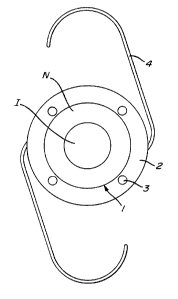
The embodiment shown in Figure 2, of a multifocal,
intraocular artificial opthalmic lens has in the center
of the optical lens portion 1 a far range F in the
form of a circular area, and an annular near range
zone N disposed concentrically around it; these are
followed radially towards the periphery by an additional
annular, concentrically disposed, far range zone F. It
is also possible, however, to dispose the near range zone
N in the center of the optical lens portion 1 and a
concentric annular far range zone F around it, and so
on. In the peripheral annular lens portion 2, which is
not optically active, the bores 3 are provided, whereby,
as in the embodiment in FIgure 1, the lens can be turned
to a suitable position, if necessary, after the implan-
tation of the lens and before the final closing of the
eye. These bores 3 are so arranged that they do not
interfere with the optical functioning of the lens. The
lens furthermore has the holding loops 4 whereby the lens
can be f ixed .
1332491
The embodiment in Figure 3 is of the bivisual type like
the embodiment in Figure 1, but the line of separation
between the near range zone N and the far range zone F runs,
when the lens body is installed, from the upper margin of the
lens to the bottom margin of the lens, and separates the
optical lens portion 1 into two halves of which the one half
forms the far range zone F and the other half the near range
zone N. With the lens inserted into the eye, the near range
zone N is situated closer to the wearer ' s nose than the far
range zone F. In this example, again, the bores 3 are
disposed in a lens area close to the lens margin, so that the
optical function of the lens will not be impaired. Holding
loops 4 serve to f ix the lens in the eye .
In the embodiment represented in Figure 4, two far range
zones F and two near range zones N of sector shape are
provided, and have equal sector angles. In the embodiment
represented, the sector angles are 90. It is, however, also
possible to provide a greater number of near and far range
zones with correspondingly smaller sector angles. ~he near
and far range zones N and F are disposed alternately around
the lens axis. Bores 3 are situated in a peripheral lens
portion 2, which is optically inactive. Fixation means 4
-- 10 --
again serve to fix the lens in the eye. 1332491
Other fixation means can be provided for the artificial
opthalmic lens . Known f ixation means are described in
German publications OS 25 04 540, 26 05 847, 26 54 999 and 27
25 21 9 .
In Figure 5, there is shown in section an embodiment of
an artificial intraocular lens which consists of a flexible,
transparent envelope 5 filled with a transparent fluid. This
envelope 5 with the fluid therein substantially forms the
optical lens portion. In Figure 5 is represented the state
of the lens for near vision. The envelope filled with the
transparent fluid is attached to the ciliary muscle of the
eye by means of a fastening fringe 6 which is anchored in the
envelope. In this manner the ciliary muscle acts as it does
on the natural eye lens, i.e., when the ciliary muscle
contracts, the illustrated near action of the lens represen-
ted in Figure 5 results, since the lens becomes more spheri-
cal and thus receives a greater refracting power. When the
ciliary muscle elongates, a tension is exerted on the
envelope 5 filled with the transparent fluid and flattens the
latter so that it is given the shape represented in Figure 6.
The lens then has a reduced refracting power, and serves for
far vision. In this manner a continuous change of focus from
-- 11 --
1332491
near vision to far vision can be made possible in conjunction
with the action of the ciliary muscle.
In Figure 7 is shown a top view of the embodiment
represented in cross section in Figures 5 and 6, and the
anchoring of the fastening fringe 6 in the flexible envelope
body 5 can also be seen.
It will be understood that the specification and examples
are illustrative but not limitative of the present invention and
that other embodiments within the spirit and scope of the
invention will suggest themselves to those skilled in the art.
-- 12 --