Language selection

Search

Patent 1332506 Summary

Third-party information liability

Some of the information on this Web page has been provided by external sources. The Government of Canada is not responsible for the accuracy, reliability or currency of the information supplied by external sources. Users wishing to rely upon this information should consult directly with the source of the information. Content provided by external sources is not subject to official languages, privacy and accessibility requirements.

Claims and Abstract availability

Any discrepancies in the text and image of the Claims and Abstract are due to differing posting times. Text of the Claims and Abstract are posted:

  • At the time the application is open to public inspection;
  • At the time of issue of the patent (grant).
(12) Patent: (11) CA 1332506
(21) Application Number: 545691
(54) English Title: FEED APPARATUS FOR A FURNACE
(54) French Title: DISPOSITIF D'ALIMENTATION D'UN FOUR
Status: Deemed expired
Bibliographic Data
(52) Canadian Patent Classification (CPC):
  • 39/59
(51) International Patent Classification (IPC):
  • C21B 7/18 (2006.01)
  • F27B 1/20 (2006.01)
(72) Inventors :
  • HENNEKEN, BERNHARD (Germany)
  • KAMMERLING, BRUNO (Germany)
  • SCHOLZ, ECKHARD-K. (Germany)
  • SCHRODER, WOLFGANG (Germany)
  • KRAUSE, HANS (Germany)
(73) Owners :
  • SMS SCHLOEMANN-SIEMAG AG (Germany)
(71) Applicants :
(74) Agent: GOWLING WLG (CANADA) LLP
(74) Associate agent:
(45) Issued: 1994-10-18
(22) Filed Date: 1987-08-31
Availability of licence: N/A
(25) Language of filing: English

Patent Cooperation Treaty (PCT): No

(30) Application Priority Data:
Application No. Country/Territory Date
P 36 32 724.7-24 Germany 1986-09-26

Abstracts

English Abstract


Bell-and-hopper apparatus for a shaft furnace comprises
two feed hoppers (3, 7), of which the upper feed hopper (3) is
rotatable through a drive device and defines a lock chamber which
is closable in pressure-tight manner by means of a stationary hood
(4) equipped with charging flaps (2). For sealing of the hood (4)
against the upper hopper (3), an encircling flexible, inflatable
bellows (6) is arranged at the hood (4) and is pressable pneumatic-
ally or hydraulically against the wall of the upper hopper (3).
during charging of the upper hopper (3), one of the charging flaps
(2) is opened, the bellows (6) is free of pressure and the upper
hopper (3) is rotated during or shortly after the charging. For
charging of the lower hopper (7), the flaps (2) of the upper
hopper (3) are closed, the bellows (6) is inflated and the upper
lock chamber (3) is disposed under excess pressure.


Claims

Note: Claims are shown in the official language in which they were submitted.


5
CLAIMS
1. Feed apparatus for a furnace, comprising, in combination:
(a) a stationary hood:
(b) selectively openable charging device provided in said hood
and defining a charging passage therethrough;
(c) an upper feed hopper rotatably mounted below said hood
for rotation about a vertical axis;
(d) drive means for selectively rotating said upper feed hopper
relative to the hood;
(e) selectively engageable and disengageable sealing means
adapted to sealingly connect the stationary hood and the
upper feed hopper; and
(f) a lower feed hopper adapted to receive the charge from the
upper feed hopper.
2. The feed apparatus of claim 1, wherein the sealing means
expandable contractible bellows and means for selectively feeding said bellows
with pressurized fluid to apply the sealing means, or discharging pressurized
fluid from said bellows to release the sealing means.
3. Method of operating feed apparatus for a furnace, comprising the
steps of:
(a) providing an apparatus comprising a lower feed hopper, an
upper feed hopper defining a lock chamber, drive means to
selectively rotate the upper feed hopper, a stationary hood
for selectively pressure-tightly closing the lock chamber, an
openable and closable charging device operatively
associated with said hood, an encircling sealing element
expandable by pressure fluid to selectively pressure-tightly
seal the lock chamber with the hood;
(b) maintaining the sealing element in a contracted state
whereby the lock chamber is at a generally atmospheric
pressure;

6
(c) opening the charging device to communicate through said
hood with the upper feed hopper;
(d) rotating said upper feed hopper while feeding a charge into
same through said charging device or shortly thereafter;
(e) stopping the rotation of the upper feed hopper;
(f) closing the charging device;
(g) expanding said sealing element to sealingly connect the
lock chamber with the stationary hood;
(h) feeding the charge from the upper feed hopper to the lower
feed hopper while subjecting the lock chamber to a
superatmospheric pressure;
(i) bringing the lock chamber back to atmospheric pressure;
(j) bringing the sealing element back to the contracted state
and repeating steps (b) through (j).
4. A furnace charging double-sluice throat stopper construction
comprising a stationary hood, an upper sluice hopper rotatably mounted below
and sealable with said hood, drive means connected to said upper sluice
hopper for rotating said upper sluice hopper around a substantially vertical axis
below said hood, at least one charging chute mounted on said hood and
opening into said hood and having a lower end entering into said hood with at
least one charging flap valve, and means for pressure-sealing said upper sluice
hopper in respect to said hood and a lower sluice hopper arranged for charging
by said upper sluice hopper.
5. The furnace charging double-sluice throat stopper construction of
claim 4, wherein said sealing means comprises an expandable bellows, means
mounting said bellows in a position between said hood and said upper sluice
hopper to apply a pressure-sealing engagement of said bellows when in
expanded condition to effect a sealing therebetween.
6. The furnace charging double sluice throat stopper construction of
claim 4, wherein the lower sluice hopper is positioned below said upper sluice
hopper, a vertical pipe member is journaled in said hood for movement
upwardly and downwardly through said upper sluice hopper and having a

7
distributor bell at its lower end which is engageable with a lower end of said
upper sluice hopper to close it and is movable downwardly from said upper
sluice hopper to open said upper sluice hopper, a rod member being movable
upwardly and downwardly within said vertical pipe member and having a lower
end below the distributor bell at the lower end of the upper sluice hopper and
terminating in a distributor bell for the lower sluice hopper engageable with a
lower end of said lower sluice hopper and movable outwardly therefrom to
open said lower sluice hopper.
7. The feed apparatus of any one of claims 1, 2, 4 or 5, wherein the
sealing means includes hydraulically expandable bellows.
8. The feed apparatus of any one of claims 1, 2, 4 or 5, wherein the
sealing means includes pneumatically expandable bellows.

Description

Note: Descriptions are shown in the official language in which they were submitted.


1332506
FEED APPARATUS FOR A FURNACE
BACKGROUND OF THE INVENTION
The invention relates to a furnace charging construction and in particular
to a new and useful throat stopper for shaft furnaces, in particular blast
5 furnaces with two hoppers, of which the upper hopper is rotatable via a drive
device and to a method of operating the furnace charger.
Most of the known devices for introducing and distributing the charges
for the burdeniny of blast furnaces are built on what is called the McKee
principle. In this arrangement with two bells, a large bell in the lower region
10 and a smaller bell in the upper region, the two bells being arranged one above
the other, the upper hopper is rotatable.
The McKee throat stopper has the advantage, among others, that its
overall height is relatively small, an advantage which is significant with respect
to maintaining the lumpiness of the charged material. A disadvantage of this
15 type of stopper, which may be termed a single-chamber stopper because the
upper hopper is not formed as a sluice chamber, consists in that the sealing of
the lower distributor bell relative to the sluice chamber wall constitutes a
problem in particular because of the relatively large seal elements. This seal
is, for one thing, under heavy stress due to wear by the abrasive charge
20 material, but, for another, it is also problematical because of possible
deformations due to uneven gas temperature distribution over the cross section
of the furnace. As soon as a leak occurs at any point of the seal, dust
particles are entrained with the outflowing gases due to the high pressure in
this zone, and they will very soon increase the leaks. This source of dust
25 constitutes an unacceptable environmental pollution, not to mention the fact
that the seal elements must be replaced frequently.
To remedy this situation, it has been proposed before to design a throat
stopper of this kind in such a way that the lower large bell need no longer forma gasproof seal. This is done in that the rotary distributor closed by the bell is
30 disposed in a tightly closed envelope.
SUMMARY OF THE INVENTION
The invention provides a furnace charging double-sluice throat stopper
construction where the problem of the seal between the lower distribution bell

1332501~
-2-
and the lower sluice chamber can be neglected but the advantages of the
known throat stopper with regard to a low overall height are preserved.
The invention adopts means different from the above mentioned known
improvement. According to the present invention, the upper hopper is
5 designed as a pressure-proof sluice chamber comprising a pressure-proof
stationary hood placed on a rotary hopper.
The throat stopper according to the invention has a low overall height.
This means a low height of fall for the charge material (coke, cinders, pellets,etc.) and, resulting therefrom, a small fines fraction of the charge material.
The seal problems no longer have the previously mentioned significance
because with the double sluice, according to the invention, it is not possible
that solids-laden gases are forced out of the blast furnace throat via the throat
stopper into the atmosphere in an uncontrolled manner.
With the arrangement according to the invention, when the upper sluice
15 chamber is placed under positive pressure for charging the lower sluice
chamber, the inflated bellows at the hood of the upper sluice hopper presses
against the sluice chamber wall and provides for an absolute pressure-proof
charging device. In accordance with the automatic charging program, the
upper sluice hopper rotates during, or shortly after, the filling with the charging
20 valve open and with the upper sluice chamber pressure-less.
Accordingly, it is an object of the invention to provide a charging throat
stopper construction for furnaces which includes a stationary hood and an
upper sluice hopper portion which is rotatably mounted below the hood and
sealable thereto and which is driven by a drive connected thereto and which
is equipped with at least one flap valve for opening and closing the chamber,
said hopper having means for closing it so that it is pressure-tight.
A further object of the invention is to provide a furnace with a throat
head entrance design for charging it which is simple in design, rugged in
construction and economical to manufacture.
The various features of novelty which characterize the invention are
pointed out with particularity in the claims annexed to and forming a part of
this disclosure. For a better understanding of the invention, its operating
advantages and specific objects attained by its uses, reference is made to the

1~3~5~i
-3-
accompanying drawings and descriptive matter in which preferred
embodiments of the invention are illustrated.
BRIEF DESCRIPTION OF THE DRAWINGS
In the Drawings:
FIG. 1 is a transverse section through a furnace charging double-sluice
throat stopper constructed in accordance with the invention; and
FIG. 2 is a detailed sectional view on a larger scale showing the seal
between stationary hood and upper sluice hopper by a flexible, inflatable
balloon .
GENERAL DESCRIPTION OF THE PREFERRED EMBODIMENTS
Referring to the drawings, in particular, the invention embodied therein
comprises a furnace charging double-sluice throat stopper construction,
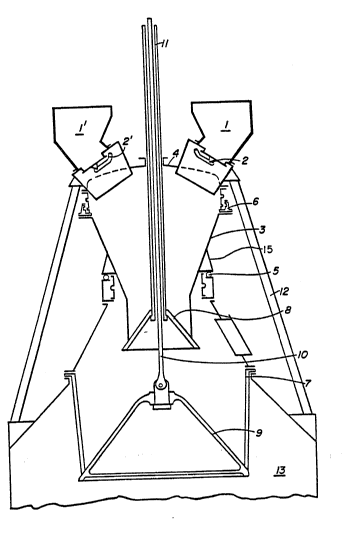
particularly for blast furnaces which includes a stationary hood 4 which carriestwo charging chutes 1, 1 each having a closeable charging flap valve 2. The
hood 4 and the chutes 1 are supported at a fixed elevation on struts 12.
In accordance with the invention, an upper sluice hopper 3 is rotatably
mounted below the hood 4 in a position in which it can be sealed to the hood
by sealing means 6 which can be applied or released and which, in the
embodiment shown, comprises inflatable bellows. The feature of the
20 construction is that the upper sluice hopper 3 is rotated by means of a drive5 having associated rotation support above a lower sluice hopper 7.
FIG. 1 shows the upper region 13 of the blast furnace, called a blast
furnace throat, with a furnace charging double-sluice throat stopper 15
construction disposed thereabove. The double-sluice throat stopper
construction 15 comprises charging chute 1 and 1' charging flap valves 2, 2'
of a stationary hood 4. The throat stopper also includes an upper sluice hopper
3 with a distributor bell 8, and a lower sluice hopper 7 with a distributor bell9.
The upper sluice hopper 3 can be set in rotation by a drive 5.
The stationary hood 4 is sealed relative to the upper rotatable sluice
hopper 3 according to FIG. 2 by means of a peripheral flexible bellows 6. This
bellows can be inflated pneumatically or hydraulically and, in the inflated state,
it applies at 14 against the wall of the upper sluice hopper 3 and against a
flange 20 on the hood 4.

~33250~
-4-
FIG. 2 shows the bellows 6 in the pressureless state. The lower part of
the hood 4 is compensatory in design.
When for charging the lower sluice hopper 7, the upper sluice hopper 3
is set under positive pressure, the charging flap valves 2 are closed and the
5 bellows 6 is inflated. The distributor bell 8 is raised on the vertical pipe
member 11, while the raised distributor bell 9 is in a closed position.
For charging the upper sluice hopper 3, one of the charging valves 2 is,
as a rule, open, the bellows 6 is pressureless, and the distribution bell 8 is
closed against the bottom of the upper sluice hopper 3.
During the charging of the upper sluice hopper 3 or shortly after the
filling, the upper sluice hopper 3 is set in rotation by means of the drive 5.
Opening of the distributor bell 9 by lowering the rod 10 takes place with
the distributor bell closed.
While specific embodiments of the invention have been shown and
15 described in detail to illustrate the application of the principles of the invention,
it will be understood that the invention may be embodied otherwise without
departing from such principles.

Representative Drawing
A single figure which represents the drawing illustrating the invention.
Administrative Status

For a clearer understanding of the status of the application/patent presented on this page, the site Disclaimer , as well as the definitions for Patent , Administrative Status , Maintenance Fee  and Payment History  should be consulted.

Administrative Status

Title Date
Forecasted Issue Date 1994-10-18
(22) Filed 1987-08-31
(45) Issued 1994-10-18
Deemed Expired 2007-10-18

Abandonment History

There is no abandonment history.

Payment History

Fee Type Anniversary Year Due Date Amount Paid Paid Date
Application Fee $0.00 1987-08-31
Registration of a document - section 124 $0.00 1987-11-03
Maintenance Fee - Patent - Old Act 2 1996-10-18 $100.00 1996-09-20
Maintenance Fee - Patent - Old Act 3 1997-10-20 $100.00 1997-09-24
Registration of a document - section 124 $50.00 1998-04-28
Registration of a document - section 124 $50.00 1998-06-26
Maintenance Fee - Patent - Old Act 4 1998-10-19 $100.00 1998-09-24
Maintenance Fee - Patent - Old Act 5 1999-10-18 $150.00 1999-09-13
Maintenance Fee - Patent - Old Act 6 2000-10-18 $150.00 2000-09-15
Maintenance Fee - Patent - Old Act 7 2001-10-18 $150.00 2001-09-18
Maintenance Fee - Patent - Old Act 8 2002-10-18 $150.00 2002-09-18
Maintenance Fee - Patent - Old Act 9 2003-10-20 $150.00 2003-09-19
Maintenance Fee - Patent - Old Act 10 2004-10-18 $250.00 2004-10-14
Maintenance Fee - Patent - Old Act 11 2005-10-18 $250.00 2005-10-04
Owners on Record

Note: Records showing the ownership history in alphabetical order.

Current Owners on Record
SMS SCHLOEMANN-SIEMAG AG
Past Owners on Record
HENNEKEN, BERNHARD
KAMMERLING, BRUNO
KRAUSE, HANS
MAN GUTEHOFFNUNGSHUTTE AKTIENGESELLSCHAFT
MAN GUTEHOFFNUNGSHUTTE GMBH
SCHOLZ, ECKHARD-K.
SCHRODER, WOLFGANG
Past Owners that do not appear in the "Owners on Record" listing will appear in other documentation within the application.
Documents

To view selected files, please enter reCAPTCHA code :


To view images, click a link in the Document Description column. To download the documents, select one or more checkboxes in the first column and then click the "Download Selected in PDF format (Zip Archive)" or the "Download Selected as Single PDF" button.

List of published and non-published patent-specific documents on the CPD .

If you have any difficulty accessing content, you can call the Client Service Centre at 1-866-997-1936 or send them an e-mail at CIPO Client Service Centre.


Document
Description 
Date
(yyyy-mm-dd) 
Number of pages   Size of Image (KB) 
Representative Drawing 2000-08-17 1 15
Cover Page 1994-10-18 1 16
Abstract 1987-08-31 1 15
Description 1987-08-31 4 120
Claims 1987-08-31 3 69
Drawings 1987-08-31 2 21
Correspondence 1998-10-07 2 50
Correspondence 2005-02-01 1 15
Correspondence 2006-01-03 1 16
Correspondence 2006-01-09 1 33
Prosecution Correspondence 1994-02-11 2 68
PCT Correspondence 1994-08-03 1 37
Office Letter 1993-08-25 1 59
PCT Correspondence 1991-02-07 1 33
Office Letter 1990-10-10 1 33
Fees 1996-09-20 1 61