Note: Descriptions are shown in the official language in which they were submitted.
` PATENT
1 332576 185/188
.
S P ~ C I E ~ I
DRIV~ SYSTEM FOR V~HIC~S
.
The present invention relates to a drive system for a
vehicle including a power plant having a longitudinally disposed
engine (i.e., which has a crankshaft extending parallel to the
longitudinal direction o~ the vehicle) for driving laterally
spaced drive wheels disposed on opposite sides of the power plant
and the same end of the vehicle as the power plant. The present
invention can be applied to a drive system for a vehicle having a
power plant disposed in a front portion of the vehicle for
driving laterally spaced front wheels or a drive system for a
vehicle having a power plant disposed in a rear portion of the
vehicle for driving laterally spaced rear wheels.
There are prior art vehicles having a longitudinally
disposed power plant which comprises an engIne, a transmis~ion,
and a differential as a unit, and which transmits output power to
drive wheels through an intermediate transmission shaft extending
through and supported in the power plan~-(see Japanese Patent
Publication No. 48-13015, U.S. Pate ~ 3,494,225, British Patent
1,032,090 and German Patent 1,555,101).
The conventional vehicle drive systems, such as the
Japanese Patent Publication 48-13015, have several problems.
Since the oil pan and the differential case, which are separate
from each other, are separately mounted on the cylinder block,
the cylinder block must have attachment regions ~or attaching the
differential case as well as the oil pan. Therefore, the
cylinder block is required to have higher accuracy and more
excellent physical properties than the oil pan and the
~,
"` ' .
~ 4
.: ., . . , . :.
.. . . . . . .
PATENT
1332576 185/188
differential case. Since the cylinder block is complex in
configuration and structure and very large, the prior art
arrangements resulted in a substantial increase in the cost of
the entire engine. Moreovsr, since the cylinder block and the
differential are positioned on one side of the crankshaft and are
heavy, the prior art layout makes the weight balance of the
overall engine very poor, whereby the power plant will vibrate
during operation, e~pecially during high-speed operation.
In view of the above shortcomings of the conventional
drive systems, it is an object of the present invention to
provide a drive system for a vehicle which will reduce the
complexity of the cylinder block, produce a better weight
~alance, and reduce the cost of the power plant.
To accomplish the above object, there is provided in
accordance wi~h the present invention a drive system for a
vehicle comprising a power plant including an engine, a
transmission, and a differentialj the power plant being disposed
longitudinally with respect to the vehicle such that the
crankshaft of the engine is oriented in the longitudinal
direction of the vehicle, the power pla~ ~eing operable to drive
laterally spaced drive wheels dispo~d on opposite sides of the
power plant at the same end of the vehicle, characterized in that
the engine has a cylinder block inclined in one lateral direction
of the vehicle, a differential case housing the differential and
separate from the oil pan is joined to a lower portion of the
cylinder block and is coupled in parallel relation to other side
of the oil pan which faces away from the direction in which the
cylinder block is inclined, and an intermediate transmission
shaft extends through and is supported in the cylinder block and
~:
,
.'.`, `! ` ', ` '
~.' `.`':,` ~
PATENT
1 3 3 2 5 7 6 185/188
the differential case, whereby the differential and one of the
drive whee s are operatively coupled to each other through the
intermediate transmission shaft.
With the above arrangement of this invention, when the
engine is operated, the engine output power is transmitted
through a clutch, the transmission, and a shaft to the
differential, from which the power i8 transmitted through the
intermediate transmission shaft, a universal joint, a drive axle,
and another universal joint to a drive wheel remote from the
differential, and the power also is transmitted through a
universal joint, a drive axle, and a universal joint to the drive
wheel near the differential.
The cylinder block of the engine, which is the drive
unit of the power plant, is inclined in one of the lateral
directions of the vehicle body, lowering the height and hence the
center of gravity of the power plant. The differential is
disposed remote from the inclined cylinder block and, as a
result, the entire drive system is well balanced in weight.
The oil pan is separate from the engine and is
removably joined to the lower portion o~~the engine. The
differential case which is separate ~rom the oil pan is removably
joined to the oil pàn. The cylinder block which would otherwise
be required to have a higher degree of accuracy than the oil pan
and the differential case and to be made of a material having
better physical properties than the oil pan and the differential
case, is simpler in construction and configuration and is smaller
in size. ~Therefore, the engine itself, which is the drive unit
of the power plant, is greatly reduced in cost.
.
.:
:. .;, ~/
, - :, . . .
.. . .. . . . . ..
PATENT
185/188
1 332576
An embodiment of the present invention will herein-
after be described with r~ference to the drawings, wherein:
FIG. 1 is a schemat~c plan view of a drive ~ystem for a
vehicle according to the present invention;
FIG. 2 is detailed cross-sectional front elevation view
taken along the line II-II in Fig. 1;
FIG. 3 is a fragmentary cro~s-sectional plan view taken
along the line III-III in Fig. 2; and
FIG. 4 is a fragmentary cro s-sectional plan view taken
along the line IV-IV in Fig. 2.
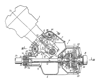
In this preformed embodiment of the invention, a power
plant P comp~ising an engine 1, a clutch 2, a transmission 3, and
a differential D as a unit is longitudinally installed on a
vehicle V (i.e., the engine l has a crankshaft 5 extending
parall~l to the longitudinal axis of the vehicle V). The output
power from the power plant P is transmitted through universal
joints Jt, Jrl drive axles Sr, se, and universal joints Je, Jr2
to laterally spaced front wheels Wr, we as drive wheels.
As shown in FIGS. 2 and 3, the engine 1, which is the
drive unit of the power plant P, has a ~ylinder axis Ll - L
inclined (at about 450) from the ve ~ical in one of lateral
directions of the vehicle V (i.e., to the right-hand side as
viewed in the direction in which the vehicle V runs forwardly).
Thus, the cylinder block 6 of ths engine 1 is inclined in the
same direction. The cylinder block 6 includes a crankcase 7 in
its lower portion. The crankcase 7 has an open lower surface 71
which is inclined along a plane normal to the cylinder axis Ll -
Ll. An oil pan 8 is joined to the inclined open lower surface
with a seal member interposed therebetween. The oil pan 8 has a
,
`''`
.~k` ` 't'~
~}::
` PATENT
185/188
1 332576
concave outer surface ex~ending along the crankshaft 5 and facing
away from the direction in which the cylinder block 6 is
inclined. A differential case 11 housing a differential D is
disposed closely and parallel to the concave outer surface of the
oil pan 8. The differential case ll is fixed to the outer
surface of the oil pan 8 by means of a plurality of bolts 22.
The crankshaft 5 is rotatably supported in the
crankcase 7 by means of bearing members 9 and bearing caps 10
fixed to the bearing members 9.
An intermediate transmission shaft 12 which lies
substantially perpendicularly to the crankshaft 5 extends
substantially horizontally through the crankcase 7, the oil pan
8, and the di~ferential case 11. The intermediate transmission
shaft 12 has one end rotatably ~upported in the crankcase 7 by a
bearing holder 14 (described in detail below) and the other end
rotatably supported in a bearing region 13 in the differential
case 11 by means of a taper roller bearing 24. That other end of
the intermediate transmission shaft 12 extends through the taper
roller bearing 24 into the differential case 11 and is coupled to
a pinion driver gear 20 of the different~ial D. The dlfferential
D is positioned away from the incli ~d cylinder block 6, as
described above. Therefore, the cylinder block 6 and the
differen~ial D, both of which are heavy, are disposed on opposite
sides of the crankshaft 5, making the power plant P well balanced
as a whole. The differential D is of a kno~n structure
comprising a differential housing 15 rotatably supported in the
differential case 11 by means of taper roller bearings 24, 33, a
large-diameter driven gear 16 fixed to an outer periphery of the
differential housing 15 and operativsly coupled to a propeller
e
PATENT
185/188
1 332576
shaft 4 extending from the transmission 3, a pair of differential
pinion gears 18, 19 supported in the differential housing 15 by
means of a pin 17, and a pair of pinion driver gears 20, 21
meshing with the differential pinion gears 18, 19. The pinion
driver gear 20 is splined to the inner end 121 of the
intermediate transmission shaft 12. The other pinion driver gear
21 is splined to the universal joint Je1 The bearing region 13
includes an oil seal 25 near the taper roller bearing 24,
providing an oil tight seal between the intermediate transmission
shaft 12, and the differential case 11. A similar oil seal is
provided between the intermediate shaft 12 and the oil pan 8
adjacent the seal 25.
A bearing region 32 is disposed on an outer wall of the
differential case 11 in axially opposite relation to the bearing
region 13. The inner end of the universal joint Jel is rotatably
supported by roller bearing 33 in the bearing region 32. The
inner end of the universal joint J~l projects into the
differential case 11, extends through the differential housing 15
of the differential D, and i6 splined to the pinion driver gear
.~ ............................................. ..
; 21. The universal j~int J~l is coupled~ o the left-hand drive
~ wheel we through the drive axle se ~d the other universal joint
'' Je2.
The bearing holder 14 is ~eparate from the engine 1 and
includes a bearing sleeve 141 having a plurality of attachment
~ arms 142. The bearing holder 14 is detachably fixed to an outer
: peripheral surface of the crankcase 7 by bolts 27 extending
through bolt holes (not shown) defined in the respective
- attachment arms 142 and threaded into the wall of the crankcase
7. The outer end of the intermediate transmission shaft 12 which
l,j. , ~, . ~.
PATENT
1 3 3 2 57 6 185/188
projects outwardly through a hole 28 defined in the crankcase 7
is rotatably supported in the bearing sleeve 141 by a ball
bearing 29. The ball bearing 29 is retained in the bearing
holder 14 by a step 143 in the bearing sleeve l41 and a circlip
or retaining ring 30 fitted in the bearing holder 14. An
oil-tight seal is provided between the bearing sleeve l41 and the
intermediate transmission shaft 12 by means of an oil seal 31
fitted in the bearing sleeve 141 close to the ball bearing 29.
The universal joint Jr1 iR splined to the outer end of
the intermediate transmission shaft 12, and the right-hand drive
wheel wr is coupled to the universal joint Jr through the drive
axle Sr and the other universal joint Jr2.
As illustrated in FIGS. 2 and 4, a pair of balancer
shafts 35, 36 parallel to the crankshaft 5 are rotatably
supported in the crankcase 7 of the cylinder block 6, with one of
the balancer shafts 35, 36 being disposed on each side of the
crankshaft 5. The balancer shafts 35, 36 have respective weights
35w, 35w. The balancer shafts 35, 36 are operatively coupled to
the crankshaft 5 through a timing transmission device 37 to
rotate in opposite directions. ~
; The timing transmission d ~ice 37 comprises a driver
:~ pulley 38 fixed to the crankshaft 5, a first driven pulley 39
fixed to one of the balancer shafts 35, a second driven pulley 40
fixed to an intermediate transmission shaft 42 rotatably
supported in the crankcase 7 close and parallel to the other
balancer shaft 36, an endless timing belt 41 trained around the
driver and driven pulleys 38, 39, 40, a driver gear 43 fixed to
the intermediate transmission shaft 42 adjacent to the~second
driven pulley 40; and a driven gear 44 fixed to the balancer
.~ . .
. : 7
:.
PATENT
1 3 3 2 5 7 6 185/188
shaft 36 and held in mesh with ths driver gear 43. The number of
teeth of each of the first and second driven pulleys 39, 40 is
half of the number of teeth of the driver pulley 38, and the
gears 43, 44 have the same number of teeth. when the crankshaft
5 is rotated, the balancer shafts 35, 36 are rotated in mutually
opposite directions at a speed which is twice the speed of
rotation of the crankshaft 5 for canceling out the secondary
inertial force of the reciprocating mass of the engine 1 with the
combined centrifugal forces of the weights 35w, 36w.
The operation of the drive system now will be
described. When the engine 1 of the power plant P is operated,
the output power thereof i5 transmitted from the clutch 2 and the
transmission 3 through the propQller shaft 4 to the differential
D, from which it is transmitted through the intermediate
transmission shaft 12, the universal joint Jr1, the drive axle
Sr, and the other universal joint Jrl to the right-hand drive
. wheel Wr, and from which it also is transmitted through the
universal joint Je1, the drive axle se, and the other universal
joint Je2 to the left-hand drive wheel we.
:. The differential case 11 is ~ eparate component from
the oil pan 8 and is coupled in par ~lel relation to the oll pan
8 which in turn is joined to the lower portion of the cylinder
block 6. The cylinder block 6 is therefore not required to have
any attachment region for attaching the differential case 11
thereto. Thus, the cylinder block 6 is simplified in
configuration and construction, and is compact.
The cylinder block 6 is required to be more accurate in
- dimensions, machining, etc., and have better physical properties
than the oil pan 8 and the differential case 11. With the
PATENT
185/18
1 332~76
cylinder block 6 being simpler in configuration and construction
and more compact, as described abov~, the cost of manufacture of
the engine is greatly reduced. In addition, the cylinder block
and the differential case,can be made of different materials.
The overall h~ight and the center of gravity of the
power plant P are lowered by tilting the cylinder block 6 of the
engine 1 in one lateral direction of the vehicle V. The
differentiai D is disposed remotely from the inclined cylinder
block 6. Since the cylinder block 6 and the differential D, both
of which are heavy, are located on each side of the crankshaft 5,
the weight of the power plant p is well balanced. As a result,
vibration of the power plant P during operation thereof is
reduced, and the structure by which the power plant P is mounted
on the vehicle body is simplified.
.:. ~ .