Note: Descriptions are shown in the official language in which they were submitted.
43240 C~N 6A
,. . .
11 33271~
FILTER ELEMENT
The present invention relates to filtration elements
~lsed in respirators or face masks. In another aspect, the
present invention relates to filtration face masks or
respirators with detachable filtration elements.
Filtration face masks or respirators are used in a
wide variety of applica~ions when it is desired to protect
a human'~ respiratory system from particles suspended in
the air or from unpleasant or noxious gases.
Filter elements of respirators may be integral to the
body of the respirator or they may be replaceable, but in
either case, the filter element must provide the wearer
with protection rom airborne particles or unpleasant or
noxious gase~ over the service life of the respirator or
filter element. The respirator must provide a proper fit
to the human face without obscuring the wearer's vision and
it is desirable that a respirator require a minimum of
effort to draw air in through the filter media. This i~
rePe~red to a~ the pressure drop across a ma~k, or
b~eathing resistance.
To achieve the levels o~ filter per~ormance such as
those definad in 30 C.F.R~ 11 subpart K 11.130~11.140-12
~19~7), DIN 3181 Part 2, "~tem~llter Eur Atemschultzgerate"
~March, 1980), BS 2091, "Respirators or Protection Against
HarmPul Dusts and Gases" (1969), and BS 4555, "High~
Effeciency Dust Respirators" ~1970) the number ~ layers of
ilter material, filter material type, and available ;~
35 filtration area are important factors in filter ~`~
~' ` ! . ~
,,...~ .
.S c~ Q~eR~I P~C~ 5
--2--
13 3 ~
element design. The present invention provides a means of
more fully utilizing a filter element's available
filtration area by properly managing air flow through the
filter material of the filter element. Proper management of
air flow can also prevent premature loading of the filter
material immediately opposite the breather or inhalation
tube, which can cause the filter element to collapse over
the breather tube, thereby restricting inhalation and
shortening the service life of the filter element.
Various filter element designs have been proposed to
provide as much filter surface area as possible while
minimizing the obstruction to the wearer's vision, and/or
1~ the pressure drop across the mask. U.S. Pat. No. 2,320,770
(Cover) discloses a respirator with detachable filter
elements. The filter elements are preferably rectangular
and are made from a sheet of filter material with all open
sides sewn closed. The filter element has a hole adapted
to be attached to the body of the mask. Cover asserts that
after being sewn, the filter element can be turned inside
out so the seams and folds cause the bag to a~sume a shape
and curvature which tends to keep the sides of the bags
apart without the aid of an additional spacing element.
Incoming air is apparen~ly intended to travel through
either the ~ront or back sides of the bag into the space
between these sides and then through the hole in~ide the
mask. U.S. Pat. No. 2,220,37~ (Lewis) dlsclo~es a
re6pirator which includes a rigid mask and a aee mold
attached to the mask. The rigid mask includes an air inlet
opening and ~iltering means covering the open~ng, The `-
Piltering means comprises a shell havlng pe~aration~ on at
lea6t thre~ sldes/ ~iltering material located inside the
shell, and a filter spreadlng member adapted to hold the
filtering material in a position exposing the filtering
materi~l to direct contact with the air entering the
perforations. U.~. Pat. No. 2,295,119 (Malcom et al.~
discloses a respirator comprising a face piece adapted for
the wearer's nose and mouth attached to two removable,
-3- ~3~271~
egg-shaped filter boxes. The filter boxes have inner and
outer, perforated members or covers which form a filter
chamber, and two filter elements positioned between the
inner and outer members of the filter box whose peripheral
portions are compressed and sealed hetween the outer and
inner members of the filter box. One of the filter
elements is attached to the filter box and face piece by a
0 locking member which secures the filter element around the `
air entrance opening of the face piece. Preferably, the
filter box also includes a means to engage the outer filter
element and space it from the inner filter element inside
the filter box such as a member in the shape of a reverse
curve which is.part of the locking member which clamps the
filter material around the air entrance opening of the face
piece. U.S. Pat. No. 2,206,061 (Splaine) discloses a
respirator comprising a face piece adapted to fit over the
nose and mouth of the wearer which is adapted to fit into
the open ends of two filters. The filters extend laterally
in opposite directions from the face piece. The ~ilters
are relatively narrow, tapering from a rounded end at the
bottom towards the top so that the side walls substantially
meet at the top edge and contain light coil springs
extending along the bottom portion of each filter to help
keep the filSers in an expanded condition. U.S. Pat. No.
4,501,272 (Shigematsu et al.J discloses an em~odiment of a
dust-proof respirator with an intake chamber ~ssembly
comprising an intake cylinder fitted airtight into a
mounting mouth of a mask body with a front wall positioned
opposedly to the intake cylinder and a rear wall composed
o~ a ~iltration medium ~astened to the intake cylinder and
along !~he peripheral edg2 of the front wall. Filtràtion
medium ls also ~astened to the front o the intake chamber,
resulting in increased filtration area.
The present invention provides, in an easily
manufactured form, a filter element of compact size and a
nature capable of low air flow resistance and high
filtration efficiency which satisfies various performance
4 60557-3627
speclfications of U.S. and foreign countries some of which have
been set ~orth above. None of the prior art teachès a comblnation
of features like those of the present invention having the
advantages of the present invention.
The present invent~on provides a filter element
comprising (A) substantially coextensive front and rear walls
jolned to each other along their peripheral edges and each
comprislny at lea~t one layer of a filter rnaterial, (B) a porou~
layer comprlsing material selected from the group conslstiny of
woven webs, nonwoven webs, loose fibers, fiber batts, loose
particulate material, particulate material bonded together in a
porous matrix, or combinatlons thereof, said layer being contained
between the front and rear walls which ls substantially
coextensive with the walls, which malntains the walls in a spaced-
apart relationship over substantially their entire area, and which
contrlbutes no more than 50% of the total presæure drop across the
filter element, and (C) a breather tube bonded to and penetrating
the rear wall of the filter element and having a means oi~
attachment for securing the ~ilter element to a respirator face
plece.
An advantaye of the filter elements as desaribed is that
they aan be adapted to perform at hlgh e~flaienay lev~ls with
re~pect to the filt~ation of dusts, mlsts, or fumes ~ithout
produclng large pressure drops.
One emhodlment of the filter element of this lnvention
wlll permlt no more than 1.5 mg penetratlon of sllica dust wlth a
geometric mean partlale dlameter of 0.4-0.6 mlcrometer, over a 90
minute perlod, at a flow rate of 16 liters~min., measured ln
; .
C ~:
~33~7:~ ~
4a ~0557-3627
accordance with procedures set out in 30 C.F.R. 11 suhpart K
511.140-4 ~1987) and will have a pressure drop across said filter
element before the 90 minute perlod of no more than 30 mm H20 and
after the 90 minute period of no more than 50 mm H20 where said
pressure drops are measured in accordance with the procedures set
forth in 30 C.F.R. 11 subpart K 11.140-9 (1987). A second
"
:. ` .
' '''
C~ .
,
~33~f~
embodiment of the filter element of this invention will
permit no more than about 3.0 percent penetration of 0.3
micrometer diameter particles of dioctyl phthalate (DOP),
and preferably no more than about 0.03 percent, contained
in a stream at a concentration of 100 microgram/l, at a
flow rate of 42.5 liters/min. measured in accordance with
the procedures set forth in 30 C.F.~. 11 subpart K
11.140-11 (1987) and permit no more silica dust
penetration and no greater pressure drops before or after
the 90 minute period than those levels set out above
measured in accordance with the procedures speeified above.
third embodiment of the filter elements of this invention
will permit no more than 1.5 mg of lead fume penetration,
measured as the weight of lead, through a filter element
over a 312 minute period at an air flowrate of 16
liters/min and will have a pressure drop before the 312
minute period of no more than 30 mm H~0 and after the 312
minute period of no more than 50 mm H2O measured in
accordance with the procedures set forth in 30 C.F.R. 11
~ubpart R ~11.140-6 and 11.140-9 ~1987).
In the accompanying drawings:
Figure 1 is a half-mask respirator fitted with filter
elements of the present invention, one of which is shown in
an exploded manner to illustrate a means by which the
ilter elements can be ~oined to the respirator Pace piecq.
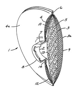
Figure 2 is a cross-section of a repre6entative Pilter
element of the invention.
The filter element 1 o this invention comprises a
Pront wall 3, a rear wall 4, and layer o~ porous material 5
servln~ to ~pace the ~ront and rear walls and Eunctioning
as a baPPle component to more evenly distribute air Plow
-6-
~L 3 3 ~
through the filter element, and a breather tube 8. The
front wall 3, rear wall 4, and baffle component 5 are
subst~ntially coextensiv~ with each other and said baffle
component 5 is contained between the front and rear walls
3,4. The filter element 1 can have various shapes such as
round, rectangular, or oval, but preferably, the ~ilter
element is round as depicted in Figs. 1 and 2. Filter
element size can vary depending upon the materials of
construction selected for the filter element 1 and upon
various design and performance criteria known to those
skilled in the art, e.g., the desired pressure drop across
the filter, and the type and amount of dust, mist, or fumes
to be removed ~rom the wearer's inhaled air. However, the
shape and size,o a filter element should not obstruct the
wearer~s eyesight when mounted on the respirator face piece
15. The front and rear walls 3,4 are joined along their
peripheral edges by a number of bonding methods such as
thermomechanical methods (e.q., ultrasonic welding),
sewing, and adhesive such that a bond 6 is formed that
prevents the leakage of air into or out o~ the filter
element 1. Pre~erably, the baffle component 5 is also
~oined to the front and rear wall 3,4 through the bond 6.
The filter element 1 has a breather tube 8 which can
have various shapes and can be formed from various
materials such as synthetic resin or ruhber. Pre~erably
the breather tube is made o~ a synthetic resin whlch i~
heat sealable, e.g., polypropylene and is cylindrical ~n
shape~ The breather tub~ 8 can be mounted anywhere along
the interlor lO or exterio~ 12 sur~ace of the rear wall 4
but pre~erably the breather tube a is mounted centrally to
the interior sur~ace lO oP the rear wall 4. The breather
tub~ 8 may be mounted to the chosen wall surface llO or 12
using any suitable means, e.g., adhesive or ultrason~c
walding. The rear wall 4 has an opening 7 adapted to fit
the breather tube 8. The breather tube 8 is bonded to the
rear wall ~ to prevent air leakage into or out o~ the
filter element 1. Preferably, the breather tube 8 has a
--7--
~ 33~7~ ~
flange 13 on the end of the breather tube 8 articulating
with the interior surface 10 of the rear wall 4. This
flange 13 provides a convenient surface 14 for bonding to
the interior surface of the rear wall 10. The other end of ~ -~
the breather tube 8 can be adapted to either join directly
with the respirator face piece 15, or as illustrated in
Fig. 1, to join to an adapter 17 which is joined to the
respirator face piece 15. One advantage of this invention
is that the wearer can conveniently test the fit or
airtightness of the seal between the wearer~s face and the
face piece 15 by pressing against the exterior surface 9 o~
the front wall 3 opposite the breather tube 8 to cause the
front wall 3 and ba~fle component 5 to collapse against the
breather tube qpening 2 thereby blocking off air flow
throu~h the filter element 1. The wearer then inhales
while the face piece 15 is held aqainst his face thereby
creating a negative pressure differential in the face
piece. The wearer can then determine whether there are
leaks between the face piece 15 and his face because these
areas will fail to seal. Since it is most convenient for
the wearer to press against the front wall with his hand,
and more preferably with one or more of his flngers, the
inner diameter (ID) of ~he breather tube is pre~erably 1.0
to 4.0 cm, and more preferably 1.5 to 3.5 cm. However, for
any particular filter element construction, e.g., ~ilter
element dlameter, materials of construction, ~ er element
thickness, and breather tube outer diameter (O~) the
3U smaller the breather tube (ID), the larger the pressure
d~op ac~os~ the ~ilter element.
Optionally, the breather tube ~ may include a valve,
t~picall~ a diaphragm valve 18 as depicted ln Fig. 1. The
valv~ allows thelwea~r to draw ~iltered air out o~ the
~ilter ele~ent 1 into the respirator face piece 15 but
prevents the wearer's exhaled air from entering the filter
element 1, thereby directing exhaled air out of the face
piece 15 through an exhalation point such as an exhalation
valve 19. Pre~erably, the optional valve is part of the
respira~or ~ace piece 15 or the adapter 17.
1~2;~ ~
The front and rear walls 3,4 are comprised of material
which can function as filter material, with or without an
outer cover or scrim. The selection of the materials o~
construction for the front and rear walls 3,4 will depend
upon design factors well known to those skilled in the art,
such as the type of environment in which a respirator
equipped with the filter elements is to be used, and
1 performance requirements such as the pressure drop across
the respirator, the type and amount of dust, mist, or fume
to be removed from the wearer's inhaled air, and design
requirements set out in 30 C . F . R . 11, subpart R
5511 . 130-11 . 140-12 ( 1987 ).
While the ~ront and rear walls 3,4 of the
filter element 1 ca~ each be comprised of only a single
layer of filter material, a plurality of layers is
pre~erred for high performance filter elements. ~y using a
plurality of layers of filter material, weh irregularities
20 which could lead to premature penetration of particles
though a single layer of filter material can be minimized.
However, very thick walls should be avoided because they
create problems in assembling the filter element 1 and
could cause the filter element 1 to become so thick that it
2'5 could obstruct the wearer's ~ision when in use. Examples
of suitable filter material include nonwoven web,
~ibrillated ~ilm web, air-laid web, sorbent-particle-loaded
fibrous web such as those described in U.S. Pat. No.
3,971,373 tBraun), glass ~ilter paper, or combin~tions
thereo~. The ~ilter material may comprise, for example,
polyolefin~, polycarbonates, polyesters, polyurethanes,
glass, cellulose, carbon, alu~ina or combinations thereo~.
Electrically charged nonwoven microiber webs ~ee U.S~
Pat. No. 4,215,682 ~ubik et al.) or U.S. Reissue Pat. No.
3~782 ~Van Turnhout)) are especially preferred. ~ filter
material comprising a plurality of layers of charged, blown
polyolefin microfiber ~BMF) web is preferred, with an
electrically charged polypropylene web being more
preferred. Carbon-particle- or alumina-particle-loaded
-9- ~L33~
fibrous webs, are also preferred filter media for this
invention when protection from gaseous materials is
desired.
The front and rear walls 3, 4 preferably include outer
cover layers 3a, 4a respectively which may be made from any
woven or nonwoven material such as spun-bonded web,
thermally bonded webs (e.g., air-laid or carded), or
resin-bonded webs. Preferably, the cover layers are made
of spun-bonded or carded, thermally bonded webs with high
hydrophobicity such as those made of polyoleflns, e.g~,
polypropylene. The cover layers protect and contain the
filter material, and may serve as an upstream prefilter
layer.
The baffle component 5 maintains the front and rear
walls 3, 4 in a substantially spaced-apart relationship
and also causes inhaled air to be drawn more evenly across
the filter element 1. This results in more even loadin~ of
dust, mist, or fumes contained in inhaled air across the
entire area of the ~ilter element 1, in longer filter
element service life, and for a given filter element
construction, lower pressure drops across the filter
element 1. The baffle component 5 can be made of woven or
nonwoven webs, loose fibers, fiber batts, loose particulate
material, 2.g., carbon particles, particulate material
bonded, e.g., with polyurethane together in a porous
matrix, or combinations thereof. ~he ba~le component
material containad between the front and rear wall~ ~orms a
porous layer that contributes no more than 50~, and
pre~rably no more than 30%, o~ the pressure drop across
the ~ilter element. Examples oP sultable baf~le component
materials are glass ~ilter paper, air-laid webs, carded
web~, fibrillated film webs, sorbent-particle-loaded
fibrous wehs, bonded sorbent particle matrices, or
combinations thereof. Preferably, the baffle component 5
comprises compressible, resilient, nonwoven web such as
those formed by performing carding or air laying `~
operations, (e.g., Rando Webbers) on blends of staple and l
--1 0--
3 ~
binder fibers such that the fibers are bonded together at
points of fiber intersection after the operation. The
baffle component 5 can be made from natural materials such
as glass, cellulose, carbon, and alumina, synthetic
materials such as poly~ster, polyamide, and polyolefi~,
polycarbonate, polyurethane, or combinations thereof.
Preferably, the baffle component 5 comprises polyester or
polyolefin. Also preferred when protection from hazardous
gases or vapors is desired are sorbent-particle-loaded
fibrous webs, and particularly carbon- or
alumina-particle-loaded webs, or sorbent-particles, e~g.,
carbon or alumina which may or may not be bonded together.
The baffle component 5 should have ~u~ficient void
volume or porosity, and be thin enough to prevent the
pressure drop across the filter element from becoming
unacceptably hi~h. It should also be thin enough to make
assembly of the filter element 1 easy and to prevent the
filter element 1 from becoming so thick that it obstructs
the wearer~s vision when the filter element 1 is mounted on
a respirator face piece. One skilled in the art will
understand that the maximum acceptable pressure drop across
the filter element 1 is determined by the comFort
reguirements of the wearer, and that as a practical matter,
sometimes these pressure drops are determined by the
standards, and measured according to the procedures set out
in 30 C.F.R. 11, subpart ~ S511.1~0-11.140-12 (19~7). The
proper selection of baEfle component thicknes~ and ba~fle
component ~tructural features ~i.e~, percent solldity
de~ln~d by the equation, ~ solidity~ 100 x [density o~ th~
porous laye~/ density of the material used to make the
porous layer], ~iber diameter or particle size, and
materi~l o~ con~ruction) can provide a thin ba~1!e
component 5, which i~ compressible is resilient, and is
rigid enough to support the front and rear walls 3,4 in a
spaced-apart relationship while maintaining an acceptable
pressure drop across the filter element 1 and while
functioning to evenly distribute dust, mist, or fume
~ 3~27~
loading across the filter element 1 surface. A thin baffle
component also permits a thinner filter element which will
be less obstructive to the wearer's vision. Generally, the
baffle co~ponent 5 should be 0.2 cm to about 4.0 cm thick,
and preferably 0. 3 cm to 1. 3 cm thick . Preferably, a
baffle component S comprising a nonwoven material should
have at least a 10 micrometer average fiber diameter and a
solidity of 11 percent or less.
Filter elements of the present invention are
further described by way of the non-limiting examples
below.
EXAMPLES
The ~ilica dust loading test was performed in
accordance with 30 C.F.R. 11 subpart ~ ~11.140-4.
The lead fume test was performed in accordance with 30
C.F.R. 11 subpart K ~11.140-6.
The DOP filter test was performed in accordance with
30 C.F.R. subpart K 11.140-11.
Pressure drops across the filter elements were
determined in accordance with procedures described in 30
C.F.R. 11 subpart K S11.140-9.
Filter elements were assembled by cutting the
appropriate diameter circular front and rear walls, baffle
component, and any cover layers fro~ various material~
which are specified below. A hole approxim~tely 3~27 om ln
diameter was cut through the rear wall o~ eaeh ~llter
element and the cover layer, if any, covering the rear
wall. Each ~ilter element had a cylindrical, 3.27 cm OD,
3.1~ cm ID, 0.572 cm long, polypropylene breather tube with
~ 0.526 am wiqe ~lange around the outer diameter Qf one
end. The un~langed end of the bre~ther tube was inserted
through the hole in the rear wall and any cover layer and
pulled through the hole until one surface o~ the flange
contacted the interior surface of the rear wall. This
flange surface was then bonded to the rear wall surface.
-12-
'~`` ~L3~7~ ~
Where the rear wall material was a polypropylene blown
microfiber ~BMF) web, ~he flange was ultrasonically welded
using a ~ranson ultrasonic welder to the interior surface
of the rear wall. where the rear wall was made of a
flber~lass material, the flanqe was bonded to the interior
surface of the rear wall using a layer of 3M Jet-meltR
adhesive 3764. The various layers were assembled in a
sandwich-like structure where the baffle component was the
innermost layer surrounded by the front and rear walls, and
any cover layers formed the outermost layers of the
sandwich. The peripheral edges of the polypropylene ~MF,
front and rear walls and baffle component were then
ultrasonically welded together. The peripheral edges of
the ~ront and r,ear walls and baffle component o~ the filter
element made with fiberglass paper were sealed using the
hot melt adhesive described above.
EXAMPLES 1-12
The effect of fiber diameter and percent solidity of a
nonwoven baffle component on pressure drop across the ~ilter
element is illustrated by the following examples. Circular
filter elements 10.16 cm in diameter with front and rear
walls made o~ 5iX layers of electrically charged
polypropylene ~MF web ~imilar to that described in US
4,215,682 (Kubik et ~1.), basis weight of approximately 55
g/m2 were constructed. The ba~fle components were 0.51 cm
thick and were made o web which was prepared by cardlng
blend~ o~ polyester ~PET~ staple ~lbers of the ~peci~ied
dlametar, and binder ~ibers ~i.e. a sh~ath/core ~iber
comprii~ing a polyester terephthalate core having a melting
temperat~r~ a~approximately 245C and a sheath comprlsing a
copolymer of ethylene terephthalate and ethylene \¦
C isophthalate, available as Melt~iFiber Type 40ao from Unitika~
Ltd, Osaka Japan) of various diameters, in a 65:35 PET/binder
~iber welght ratio and subsequently placing the carded web in
a circulating air oven at 143C for about 1 minute to
e~ P~<
-13- 13~271~i
activate the binder fibers and consolidate the ~eb. The
various solidities, of the baffle component, fiber diameters
of the PET and binder fibers, and average fiber diameters of
the fiber blends used in the baffle component web are
summarized in Table 1. The filter elements were assembled
according to the procedure described above. Pressure drops
were measured for each filter element using the procedure
referenced above. The pressure drops are summarized in Table
~0
~3~,7~
a~ ^
u~ O D ~r; r~ D O (~ ~
; ' .
~>1
r1
o ~ ~ a~ ~D ~ ~ ~ U~ a~ ,
~4 r-l ~
~1) O O r-~ r I O r-l r-~ r-1 r-l ~ O r-l r~l
3 U~
_
a) a~
.~ ~ ~
r-l ~D O
--1 r~ r~ r-l
~1 r
q `¢ ~ E~
_
E~
~ ~n
S~
r~~ r1
~r~ O
a~ ~ er ~ o o o cr ~r
O ~ IU t) t~ ~ ~ N ~ ~ t~l N
Z~ C r1 .
.q ~
~ m
a~ ~
~r~ ~¦) tl) O
r~ h cr~ a~ a~ ~) ~ ~ ~ 1~ 1~ ~ ~ ~r)
O Q~ ~ ~ ~ ~ 1 r~l r~l ~ I r-l r~l r~l
æ ~ ~ .r~
.~ .
~1 :
E~ r~l r-l r-l
~C
~:
~ ~ 3 ~
The data shows that both the average fiber diameter and
solidity of the nonwoven material comprising the baffle
component affects the pressure drop across the filter
element and that fiber diameters as low as 13.8 micrometers
5 produced acceptably low filter element pressure drops.
EXAMPLES 13~16
Circular filter elements similar to those described
10 in Examples 1-12 were assembled except that these filter
elements had baffle components made of woven (scrim) and
nonwoven materials of various thicknesses. The woven web
used to made the baffle components was a polypropylene
rectangular mesh.scrim 0.05 cm thick commercially available
15 from Conwed as ON 6200. The nonwovan web used for the
baffle component was made according to a similar procedure
used to made the nonwoven baffle web used in Examples 1-12
except that a 50:50 blend of a 51 micrometer diameter
polyester staple fiber and 20.3 micrometer diameter,
Eastman~T-438, polyester binder fiber was used, and the web
was calendered to a thickness of 0.07 cm after it came out
of the oven. The pressure drops across the filter elements
were measured according to the procedure referenced above.
25 The baffle component materials and pressure drops are
reported in Table 2.
Table 2
Pressure
Ba~le Solidity Thickness drop
30 ~xamPle _type ~ (cm)
13 Scrlma 8.1 0.05 > 100
(1 la~er)l ; j
14 Scrim 8.1 0.20 29
(4 layer~)
Nonwoven 10.7 0.20 55
(3 layer~)
16 Nonwoven 10.7 0.41 29
~6 layers)
a~ woven scrim
b) polyester nonwoven web
-16-
133~
.... . .
The data shows that woven and nonwoven baffle
components with solidities as high as 8-10.7 % and thickness
as low as 0.2 cm produced filter elements having acceptable
pressure drops. The data also shows that baffle component
solidity and thickness affect the pressure drop acrosis the
filter, so both should be considered when selecting baffle
component material.
EXAMPLES 17~22
7.6, 10.2 and 12.7 cm diameter filter elements were
prepared in the manner described above except that one set of
filter elements with these diameters had front and rear walls
made of two single layers of fiberglass paper (available from
Hollingsworth & Vose, # HE 1021 Fiberglass Paper) and another
set o~ Pilter elements with the same diameters had walls made
of a single layer of the same electrically charged
polypropylene BMF web used in Examples 1-12. The nonwoven
web used for the 0.64 cm thick baffle components used in each
filter element was made according to a similar procedure used
to make the nonwoven baffle web used in Examples 1-12 except
that a 20.3 micrometer diameter, Melty Fiber binder fiber was
used. The filter elements were subjected to the sillca dust
loading test referenced above. Dust penetratlon and initial
and final pressure dropis were measured and are reported in
Table 3. A~er testing, the filters were inspected to
determine the evenness of particulate loading acrosis the
sur~ace oE the ~ilter element. The inspected filters were
evenly lo~ded with par~iculate material over both ~he
sur~aces o~ the front and rear walls.
. " I i : , !
-17-
Table 3 133271~
Initial Final
Filter pressure pressure
Filter dia. Pen. drop drop
Example media (cm) (mg~ (mm H20) (mm H20)
17 Fiberglass 7.6 1.45 10.1 33.4
18 Fiberglass 10O2 1.49 6.3 *
19 Fiberglass 12.7 2.94 4.6 6.7
BMF 7.6 0.22 5.8 15.8
21 BMF 10.2 0.15 3 7 4 8
22 BMF 12.7 0.18 2 8 3 1
.
* Filter broke ;
The data demonstrates that charged polypropylene BMF filter
media permits less penetration of silica dust during the
test period and produces lower pressure drops across the
filter element over the test period than fiberglass paper.
Therefore, filter elements utilizing the BMF media can he
made in smaller sizes and still offer comparable
performance levels to larger filter elements using the
fiberglass media.
EXAMPLES 23-26 ~ ;
Three circular ~ilter elements having diameters o~
7.6, 10.2 and 12.7 cm were constructed according to the
procedure describ~d above, using ront and rear walls made
o~ two sin~le layers o~ flberglass paper (available from
Hollingsworth & Vose, # HE 1021 Fiberglass Paper), and
baf~le components 0.64 cm thick, made oE nonwoven baffle
component web identical to tha~ u~ed in ~xamples 17-22.
Additionally, three clrcular, 10.2 cm diameter filter
elements were constructed using front and rear walls made
o~ a single layer of the same electrically charged
polypropylene BMF web used in Examples 1-12 and 0.64 cm
thick baffle components made of the same nonwoven baffle
component web used in Examples 17-22. The filter elements
-18-
~ ~27~
used in Example 26 also incorporated a cover layer over the
front and rear walls made of material similar to the baffle
component web used in Examples 17-22, except that the web
was calendered to a thickness of 0.033 cm after it came out
of the oven~ The filters were assembled and subjected to
the lead fume loading test referenced above. Initial and
final pressure drops across the filter elements and the
level of lead fume penetration through the filters were
measured. After testing, the filter elements were visually
inspected to determine if there had been even loading of
the lead fume across the surface of the filter element.
~he inspected filters were evenly loaded across both the
front and rear wall surfaces. Filter construction,
diameter and le,ad fume penetration test data are reported
15 in Table 47
Table 4
Initial Final
Filter Pressure Pressure
Filter dia. Pen. drop drop
20 Example media (cm) ~ (mm H20) (mm H20)
23 Fiberglass 7.6 0.30 10.8 >115
24Fiberglass 10.2 0.30 6.2 >115
25Fiberglass 12.7 0.22 4.9 >115
26*BMF 10.2 0.28 3.2 ~1.5
*average of three samples
The data show~ that the polypropylene, BMF filter media
provides the wearer with protection agains~ lead fumes with
signi~icantly lower pres~ure drops than filter elements made
3~ wi~h ~ibe~glass media~
~ EXAMPLES 27-35 ! ' ;
Circular filter elements ranging in diameter from 7.6
to 10.2 cm were constructed using a single layer of
iberglass paper ~available from Hollingsworth & Vose,
HovoglasR #HB-5331 Fiberglass Paper) for front and rear walls //-
~ ":
C ~ 4k
'~?
--19--
~L 3 ~ 2 J 1~
and a 0.64 cm thick baffle component made of the same web asthe baffle components used in Examples 23-26. Additionally,
a set of circular filter elements ranging in size from 7.6 to
10.2 cm diameter with front and rear walls made of a
plurality of layers of the same electrically charged
polypropylene BMF used in Examples 1-12 and a 0.64 cm thick
baffle component made of the same web as the baffle
components used in Examples 23-26 were constructed. All
filter elements were constructed in accordance with the
procedure described above. All of the filter elements were
subjected to the DOP penetration test referenced above. The
filter wall material, number of layers oE filter material,
filter diameter, DOP penetration, and pressure drops across
the filter meas~red after the DOP penetration test are
15 surQmarized in Table 5.
Table 5
Final
Layers Filter pressure
Filter of filter Dia. Pen. drop
20 ExamPle Media media (cm) (%) (mm H20)
27 Fiberglass 1 11.4 0.015 27.5
28 8MF 5 7.6 0.Q13 29.5
29 BMF 5 8.3 0.006 25
~MF 6 10.2 0.001 20.5
31 BMF 5 10.2 0.004 16.5
32 BMF 4 10.2 0.011 13.0
33 BMF 4 7.30 0.10 25.0
34 BMF 2 7.6 2.5 12
BMF 1 7.6 30.0 5
EXAMPLE 36
3~
Five, 10.2 cm diameter, circular ilter elements
were made whichlwere identical to those used irl Example 30.
The filters were subjected to the silica dust test
re~erenced above. The average silica dust penetration
through the filter elements was 0.05 mg, the average
pressure drop across the filter element before the test was
20.5 mm H2O, and the average pressure drop across the
~ilter element after the test was 22.4 mm H2O. After the
-20-
2 7 ~ :i
test the filter elements were visually inspected to
determine the evenness of particle loading on filter
element surfaces. The inspected filter elements were
evenly loaded with silica dust over both the front and rear
walls of the filter element.
EXAMPLES 37-41
Circular filter elements similar to those
described in Examples 1-12 were assembled except that these
filter elements had baffle components made of particles of
various diameters and materials. The particulate material
when held between the front and rear walls formed a porous
layer. Several.of the examples were carbon particles
classified by sieving. One of the examples was
polybutylene resin pellets of uniform size. The pressure
drops across the filter elements were measured according to
the procedure referenced above. The baffle component
materials and pressure drops are reported in Table 6.
Table 6
~verage
particle Pressure
Baffle diameter Thickness drop
25 ~ material(mm) ~cm) ~mm H~0)
37 carbon .93 .99 47.0
38 carbon 1.09 .86 40.1
39 carbon 1.29 .89 33.9
~0 carbon 1.7 .91 32.6
~1 polybutylene 3.0 1.02 2~.7
The data shows that there is a definite
relationship be$ween~diameter and pressure drop. Particle
sizes above 1.5 mm will give acceptable pressure drops.
EXAMPLES 42-44
Filter elements 10.2 cm in diameter were constructed
using front and rear walls of a single layer of the
polypropylene BMF web used in Examples 1-12 and 0.64 cm
thick baffle components made of the same nonwoven baffle
component web used in Examples 17-22. Each filter element
had a cylindrical, polypropylene breather tube. The
breather tubes had various inner diameters, but their outer
diameter was 3.27 cm. The filter elements were assembled
according to the procedure described above and the pressure
drop across each ~ilter element was measured according to
the procedure referenced above. The breather tube inner
diameters and pressure drops are summarized in Table 7.
Table 7
Pressure
Breat,her tube drop DOP pen
ExampleID (cm) (mm H 0) _(%)
42 1.27 5.1 9.5
43 1.59 3.7 10.1
44 1.91 3.2 9.7
The data shows that for a given filter construction,
the larger the breather tube inner diameter the lower the
pressure drop across the filter element.
Various modifications and alterations of this
invention will become apparent to those skilled in the art
without departing from the scope and spirit of this
invention.