Note: Descriptions are shown in the official language in which they were submitted.
-
l333a~
A method of and an apparatus for conveying a sleeve which is
closed at one end out of a processing station and into trans-
porter means
______________________
._______ _____
The invention relates to a method of conveying a sleeve which
consists of paper, cardboard or the like and which is closed at
one end, out of a processing station and to a transporter means
and it also relates to an apparatus which is suitably construc-
ted to carry out such a method.
In the packaging industry, packages are known for holding liquids
and which are sleeve-like, being closed at one ënd by an end face
which will subsequently form the bottom or the lid. When such
liquids packagings are produced, generally there is the diffi-
culty of handling them during manufacture, filling and sealing.Usually, packagings which are filled with liquids are produced
in the following sequence, the first stage in fact being the
shaping of the sleeve which is mostly produced from paper coated
on both sides with synthetic plastics materials, after which the
sleeve is sealed at one end, then filled, sealed at the opposite
end and finally passed to a re-packing unit.
The present invention is concerned with the stage in manufacture
which follows the sealing ofthe sleeve at one end and up to the
time it is passed to a filling station.
In another connection, it is already known for a tubular or
cylindrical sleeve-like member to be formed from a web of paper
drawn off a supply roller and which is coated at least on one
side with synthetic plastics material t-o render it fluid-tight,
the sleeve being mostly formed by the application of a longitu-
dinal seam on a cut-off portion of the web, the height or width
of this part being equal to the length of the longitudinal
sealing seam.
--1--
1333~7~
It is furthermore known for such a tube or sleeve which is ini-
tially open at both ends to be sealed at one end, namely at the
end which will subsequently form the lid, with a synthetic plas-
tics material without a backing material, in that the paper sleeve
is pushed sufficiently far onto a mandrel that along the edge of
the paper tube which is disposed at the free end of the mandrel
and which, furthermore, is no longer coated with synthetic plas-
tics material, due to the cutting operation, that member which
will subsequently be the lid and which preferably has a pourer
orifice, can be integrally injection moulded in fluidtight manner.
Such a sleeve which has been closed at one end is then pulled off
the mandrel, conveyed by transporter means to the filling station
where it is filled, sealed st the end opposite the lid and then
further processed in the usual manner.
The present invention is concerned with the scraping or removal
of the sleeve from the mandrel and its insertion into the trans-
porter means which then horizontally transports in the direction
of conveyance the sleeve which is generally closed at one end
and which is in an upright position to allow liquid to be poured
into it vertically from above.
After the synthetic plastics lid has been injection moulded onto
the sleeve, it is difficult for this latter to be withdrawn
quickly from the-mandrel. Even if the sleeve were not seated on
a mandrel, it would be difficult to convey it in a short time
from a processing station in which, for example, the lid was
injection moulded into place, into the transporter means. Natu-
rally such conveyance is basically possible and in one case or
another it may even have been carried out by per se known means
within the state of the art. However, if liquids packagings are
produced from the web at high speed and at a high rate of produc-
tion, then it is necessary to provide a method and an appropriate
apparatus by which transfer from the processing station to the
transporter means can take place in a very short time. In fact,
it is only possible then for the large quantity of completed
--2--
- 133307~
packagings to be produced per unit of time. The output of such
a packaging production machine (number of packagings per unit of
time) will always depend upon that stage in the procedure or
apparatus where a bottleneck is encountered from time to time.
In the state of the art, it was difficult adequately to grip the
package at its rear edge, i.e. the edge opposite the moulded-on
lid or end member or alternatively to clamp the package at some
other location and move it from the processing station into the
transporter means by positive or frictional action.
This problem is rendered particularly difficult by the fact that
the sleeve is closed at one end. If the sleeve is supported
from the inside, generally if it is carried by a mandrel, then
the man skilled in the art will immediately appreciate the diffi-
culty that when the sleeve is stripped from the mandrel, a space
must be created between the end of the mandrel and the sleeve,
this space becoming progressively larger during conveyance or
during removal from the mandrel so that a vacuum is formed in
this space unless air is able to flow in from the outside.
Well, it was thought that a paper sleeve pushed over the peri-
phery of the mandrel and in the direction of the longitudinal axis
of the mandrel would only have to be seated loosely enough that
air flowing in during extraction would prevent the formation of
the vacuum. However, this solution was found to be inappropri-
ate because when the sleeve, and thus also its edge on which the
synthetic plastics lid is to be injection moulded without any
carrier material, is too loosely seated on the mandrel so that
when the synthetic plastics is injected, the plastic material is
forced into the gap which is made loosely possible, the
packing is not only unsightly but also becomes leaky.
Therefore, the invention is based on the problem of providing a
method of conveying a sleeve which is closed at one end and
which has the features mentioned at the outset, and also of pro-
viding an apparatus for carrying out such a conveying method, by
--3--
~33~
means of which, in spite of the evident difficulties, it is
possible in a very short time to convey sleeves from a
processing station to a transporter means, even in the case of
paper sleeves which are closed at one end by the injection
moulding of a lid.
With regard to the method, the problem is according to the
invention resolved in that the sleeve is gripped at its edges
which are in the rear in the direction of movement and is
pushed in the direction of its longitudinal axis along a
straight path and into the transporter means, air being blown
into the interior of the sleeve. The idea according to the
invention lies in the gripping of the sleeve at its edges
which are at the rear in the direction of movement, in other
words those edges which are opposite the sleeve closure. In
other words, where the sleeve is open and can be subsequently
filled, that is where the sleeve is gripped and moved by a
kind of positive engagement in the direction of its
longitudinal axis. In this direction, and it is in this that
the second consideration of the invention resides, the sleeve
offers its greatest strength and also stability of shape. In
this way, sufficient force can be exerted on the paper sleeve
to accelerate its movement so that the acceleration is great
enough and conveyance from the processing station to the
transporter means will occur with sufficient speed.
Furthermore, so that the movement in the direction of the
transporter means is still further favoured, air is blown into
the interior of the sleeve. A pressure or a cushion of air is
therefore built up behind the end face which will hereinafter
be referred to as the lid, and this helps to move the sleeve
in its direction of progress.
In a broad aspect, therefore, the present invention relates to
a method of conveying a sleeve (1) which is closed at one end
and which consists of paper, cardboard or the like, from a
processing station (3) and to a transporter means,
characterised in that the sleeve (1) is gripped by its edges
--4--
1333~
(5) which are at the rear in the direction of movement (7) and
pushed in the direction of its longitudinal axis along a
straight path (arrow 7) into the transporter means, air being
blown into the interior (16) of the sleeve (1).
In another broad aspect the present invention relates to an
apparatus for conveying a sleeve (1) consisting of paper,
cardboard or the like, from a processing station (3) into a
transporter means, characterised in that a scraper ~4) is
provided which is adapted to be driven and to move in a
translatory sense, being also capable of being brought into
engagement with that edge (5) of the sleeve (1) which is at
the rear in relation to the direction (7) of conveyance.
According to the invention, it is furthermore advantageous if
the sleeve is only gripped on a part of its rear edge which
represents not more than half thereof, by a scraper which is
in its starting position and is pulled down from a mandrel
which is carrying it and which is in the starting position,
whereupon the scraper moves back to its starting position
alongside the next sleeve. While the sleeve can be gripped
anywhere while it is
/
/
/
/
/
/
/
/
/
/
/
/
/
/
/
/
/
/
/
/
/
/
/
-4(a)-
1333~7~
being pushed onto the mandrel, so that there can scarcely be any
problem pushing the sleeve onto the mandrel with considerable
speed, scraping off is a substantially greater problem because
the said rear end is situated close to the mandrel and a man
skilled in the art would usually doubt that this could be the
sole possibility of removal. According to the invention, how-
ever, a purely frictional engagement is avoided by the fact that
the sleeve is gripped around its periphery. Despite these
doubts about gripping only over the rear edge, the invention pro-
poses that the scraper actually be applied to this rear edge andcan transmit sufficient forces to accelerate movement of the
sleeve in the direction of the transporter means.
For the case mentioned here where the sleeve is carried by a
mandrel, a particularly practical embodiment is one in which
this mandrel serves as the interior mould for an injection moul-
ding apparatus (processing station), while the outer mould, pre-
ferably in two parts, is of course moved from outside the sleeve
and against the end face of the mandrel where it is moved into a
suitable position, a process which results in closure of the
injection moulding space. When the outer mould has been opened,
the paper sleeve, closed at one end, is to be found on the man-
drel which carries it, and this position is termed the starting
position because in the case of the present invention it is con-
cerned with movement from the mandrel into the transporter means.
The "pulling down" of the sleeve from the mandrel, described
with the aforementioned features, can of course also be described
as a "pushing down", according tothe point from which the move-
ment is observed.
It will be understood that a scraper has to be moved over the
sleeve seated on the mandrel in order to be able to reach and
grip the rear edge of the sleeve and that during the pushing of
the sleeve downwards from the mandrel, it must sufficiently
travel past the mandrel for the rear edge of the paper sleeve
also to move clear of the mandrel.
--5--
13~7~
If, in per se known manner, a mandrel wheel is used, from which
a plurality of mandrels project radially outwardly in a stellate
fashion, then after the scraper has been moved away from the
mandrel, this latter can be moved out ofits so-called starting
position into a further position which is of no interest for the
invention. In the case of such a mandrel wheel or even if a
- next mandrel with a freshly moulded-on lid attached to the paper
sleeve is brought into position, then this next mandrel will
again be in its starting position. In the meantime, the scraper
ought as far as possible to return to its own starting position.
To a man skilled in the art, once the first empty mandrel has
moved away, it will be obvious initially to wait until the second
mandrel carrying a sleeve which is closed at one end is again in
the starting position before moving the scraper back into its
starting position. This position must be considered to be that
whence, shortly after it starts moving, the scraper is capable
of engaging the rear edge of the sleeve. At the same time, it
will however be appreciated that valuable time in the working
rhythm of the packaging machine will have been wasted. According
to the invention, the above-mentioned feature is mentioned for
the reason that the sleeve is, in fact, not gripped by the
scraper over its entire rear edge but only on a portion of it
which does not amount to more than half. The doubts of a man
skilled in the art ought to be the more marked for this feature,
because the total force, and thus the pressure on the rear edge
for pulling the sleeve off the mandrel with sufficient accelera-
tion, has to be transmitted to the sleeve material via just a
fraction of the rear edge. However, according to the invention
it has been found that such a solution might well be considered,
particularly if suitable conveying means are provided, as will
be described hereinaftèr.
The surprising advantage which is achieved by the fact that the
rear edge of the sleeve is only partly gripped, lies in a saving
on time. In fact, whereas after it leaves the first empty
--6--
133~
mandrel, the second màndrel with the next closed sleeve is moved
into its (for scraping) starting position, it is now according to
the invention possible for the scraper already to be moving into
its starting position while the mandrel has still not reached its
starting position. Preferably, the mandrel with the next sleeve
reaches its starting position when the scraper is also substan-
tially in its starting position. Minor differences in timing can
be overlooked.
Expediently, the invention is further implemented in that after
the sleeve has been pulled from the mandrel, this empty mandrel
is moved away out of its starting position, a new mandrel being
moved into the starting position, together with a sleeve. These
features make it possible to achieve the particularly short time
before both the parts which engage each other, namely the scraper
and the sleeve, are back in their respective starting positions.
The working rhythm of the production machine can thus be shorten-
ed so that the rate of output of the packaging machine can be
increased.
With regard to the apparatus for conveying a sleeve which con-
sists of paper, cardboard or such like, from a processing station
to a transporter means, the aforementioned problem can be re-
solved in that a scraper which is adapted to be brought into
engagement with that edge of the sleeve which is at the rear in
the direction of conveyance, is adapted to be driven with a
translatory movement. According to the invention, the scraper
is moved on a straight path from a starting position into an
extreme position and back. From the mechanical point of view,
such a movement can be carried out particularly quickly and
furthermore, the possibility of the scraper acting on the rear
edge of the sleeve is encouraged, because the direction of trans-- -
latory movement coincides with the longitudinal axis of the
sleeve, i.e. with the direction in which the stiff paper is made
available.
It is particularly preferred if, according to the invention, the
133~
scraper is mounted on a lifting rod adapted to move in the direc-
tion of its longitudinal axis and is V-shaped, when viewed in the
direction of this longitudinal axis. The lifting rod makes it
possible to carry out a rapid translatory movement in its longi-
tudinal axis and therefore the scraper is supported and moved
via a lifting rod.
If it is intended to convey round and preferably cross-sectionally
circular paper sleeves in the manner indicated according to the
invention, then the scraper should be formed to match the sleeve
periphery or the shape of the rear edge of the sleeve, in other
words it should be round. However, it is also conceivable for a
sleeve to have a rectangular or quadratic cross-section. In this
case, it has been found that scraping is possible over two of the
four edges, so that the scraper acquires a V-shape. This con-
figuration of scraper provides the advantage already mentioned
earlier that in fact after movement of the first empty mandrel
away from the site, when the scraper is in the extreme position,
the second mandrel which carries a further sleeve can be moved
into its starting position, while at the same time the scraper is
returned to its starting position. In the case of a preferred
special embodiment, if it is imagined that the angle enclosed by
the V is set at about 90 or more, then it is at the same time
evident that the V - always as seen in the direction of the longi-
tudinal axis of the lifting rod - provides a space which is only
half enclosed, or even less, while on the opposite side, prefer-
ably the side opposite the tip or edge of the V, the space is
open and in fact in this open space the second mandrel should,
according to the invention, carry the next sleeve into position,
even if the V is already there and even if the scraper which is
V-shaped when viewed in the said direction, is already on its
way back to its starting position or is already in its starting
position. The second mandrel which carries the next sleeve
ought as far as possible to be moved quickly into its starting
position and by virtue of the V-shaped construction of the
scraper, it should be capable of achieving this initial position
without regard to the location of the scraper. Evidently, the
--8--
133~
output of the machine can consequently be considerably
increased.
According to the invention, it is furthermore advantageous if
the scraper comprises an angular carrier which mounts spring
loaded gripper blocks adapted for movement in a direction at
right-angles to the inner edge on the two mutually facing inner
edges of the V. The carrier represents the rigid supporting
part of the scraper which can be moved in a translatory sense
rapidly and in a brief sequence via the lifting rod. However,
it is generally extremely difficult, with an accuracy of milli-
metres or possibly tenths of a millimetre, to move such a rigid
part up to a relatively quickly moving mandrel in such a way
that the rear edge of a paper sleeve can be reliably and securely
gripped, particularly if only a part of the total available rear
edge is to be gripped by the scraper. Without the gripper
blocks which are adapted to be movable according to the inven-
tion, such a scraper would be virtually unfeasible. According
to the invention, however, preferably one gripper block is spring
loaded and movable preferably on each inner edge in such a way
that the tolerances which have just been mentioned can be easily
bridged. It is favourable if the gripper block is produced for
instance from a material which is softer than the mandrel or the
carrier. While the mandrel, the carrier, the lifting rod and
other parts of the machine are produced from steel, aluminium,
brass or other suitable alloys, synthetic plastics material
should be used for the gripper blocks, and Teflon in particular
would be an expedient choice. This has certain self-lubricating
properties and so makes it possible for the front edges of the
gripper blocks which face the lifting rod possibly to slide
along the surface of the mandrel so that when they are in their
-starting position, they are reliably in contact with the mandrel
which is in its starting position. Then, in fact, it is reli-
ably ensured that upon switch-over of the translatory direction
of movement, those edges of the gripper blocks which face the
relevant mandrel will form-lockingly engage the rear edge of
the sleeve.
_g_
1333~7~
In the case of a sleeve which is of quadratic cross-section,
the carrier of the scraper takes the form of an angle member,
the two arms of the V forming the angle matching the cross-
sectional shape of the sleeve. This applies both to sleeves
having a parallelogram-like,trapezoidal,rectangular or also
-quadratic cross-section, to mention only a few examples. Pre-
ferably, sleeves with a quadratic cross-section are used, so that
the angle between the two arms of the V amounts to 90. Then
also the two inner edges of the carriers are at 90 to each other.
These are termed the "mutually facing" inner edges. Viewed in
the direction at right-angles to the longitudinal axis of the
lifting rod, they have a certain flatness into which a recess is
machined, so providing within the carrier and behind the respec-
tive inner edge a space in which the gripper blocks are not only
accommodated but are also capable of movement. Preferably, each
gripper block is adapted for movement or displacement in rela-
tion to the inner edge of the carrier and preferably only one
gripper block is disposed behind each inner edge of the carrier.
For easier manufacture of the carrier, this latter can be milled
out from its surface (at right-angles to the inner edge), in
order to provide the space to accommodate the gripper block. If
the gripper block is introduced into this space, two guide pins
fixed in the carrier at a distance from each other engaging
elongated holes in the gripper block so that they can guide it,
then one surface of the gripper block bears on the supporting
surface of the carrier which is on the inside of and parallel
with the outer surface of the carrier which extends at a right-
angle to the longitudinal axis of the lifting rod, while the
opposite surface of the gripper block is flush alongside the
"bottom" surface of the carrier, which is opposite the first-
mentioned surface when one looks in the direction of the longi-
tudinal axis of the lifting rod from its free end and in the
direction of its attachment. Accommodating the gripper block in
the space in the carrier behind the relevant inner edge of the
carrier is then expediently achieved by a retaining plate which
--10--
1333~8
is fixed by screws on the "bottom" surface of the carrier. In
consequence, the space in the carrier behind the relevant inner
edge is sealed on five of its six sides (if it is regarded as
rectangular or parallelepiped).
For it to function, the gripper block must project from the sur-
face of the carrier, where the inner edge is provided, i.e. that
face of the V-shaped carrier which is opposite the adjacent
surface. Therefore, we speak here also of "mutually facing inner
edges". These inner edges or the mutually facing gripper blocks
are in plan view, i.e. when one looks in the longitudinal axis of
the lifting rod from its free end in the direction of its
attachment, closed in a V-shape on one side, the point of the V
being imagined, and they are so open on the other opposite side
that during the translatory movement of the carrier, together
with its gripper blocks, any desired part of the machine or also
the workpiece could be moved into (or possibly also out of) place,
notwithstanding the position of the carrier.
Upon withdrawal of a paper sleeve from a mandrel, the paper
sleeve being closed at one end, mention was already made at the
outset of the difficulty that a vacuum might form if the sleeve
is withdrawn from the mandrel very quickly. In order to counter-
act this difficulty, it is according to the invention envisaged
that the mandrel comprise interior air passages and an insert
which forms an air outlet. So that the mandrel can be used in
the likewise above-mentioned manner as the internal mould in a
synthetic plastics injection moulding apparatus, it must have a
closed end face and in the case of a mandrel wheel, this should
preferably be at its free end. Inorder to dissipate the vacuum
which forms when the paper sleeve is withdrawn from the mandrel,
air is blown over the end face behind the lid of the paper
sleeve. For this purpose, an air outlet is required in order to
feed air to the air passages inside the mandrel. Since the syn-
thetic plastics material for forming the lid on the paper sleeve
is injected at high pressure and at a high temperature, the air
--11--
1~33~7~
outlet ought not to be of large dimensions. In practice, it
has been found that the gap for the exit of air ought not to be
greater than 0.05 mm but should as far as possible be narrower
or smaller. The difficulties which a man skilled in the art
would envisage in setting up such small air outlet slots are
overcome according to the invention by the provision of an in-
sert. From the mechanical point of view, it is possible in fact
to drill inside the mandrel suitably large air passages (long
enough and of sufficient diameter) and then it is possible to
provide a space in the form of a blind bore which is connected
to these air passages, preferably starting from the closed end
face of the mandrel and into which the insert is fitted, which
is, for example, constructed like a-plug, leaving the necessary
narrow gap free.
In this respect, it is expedient for the gap to be constructed
in the form of a plurality of concentric circles or for it to be
circular with a width of less than 0.05 mm. Consequently, the
emergence of air can be made suitably narrow and nevertheless the
overall area of the air outlet can be made sufficiently large.
In the case of a liquids packaging with a capacity of 1 litre,
it is in fact in the case of a special embodiment of a packaging
machine, desirable for the essential part of the paper sleeve to
be withdrawn from the mandrel in a half a second or less. How-
ever, this means that in a period of 0.6 to 0.3 seconds and pre-
ferably 0.4 or 0.5 seconds, a litre of air has to be blown
through the air outlet on the insert or in the case of the ima-
ginary preferred embodiment, through the circular slit which is
0.03 mm wide, into the space behind the sleeve. The details of
figures and sizes will, to a man skilled in the art, make it
obvious what advantages can be achieved by the measures accord-
ing to the invention.
At the outset, reference was made to the advantage which arises
in terms of simplification of the injection moulding tool by
reason of the fact that the mandrel onto which the paper sleeve
-12-
1~3~7~
is pushed, is also used as the interior mould. The front edge
which is opposite the already aforementioned rear edge of the
sleeve ought to receive the synthetic plastics lid which is to
be moulded onto it. After the paper sleeve has been pushed onto
the corresponding mandrel with a closed end face, this leading
edge of the sleeve ought to be positioned at a slight distance
from the rectangular or quadratic straight edge of the mandrel.
In the case of sleeves which have a rectangular cross-section,
if the side faces between the four end edges are flat, then in-
jection moulding presents the problem that undesired gaps arecreated between the correspondingly flat outer surface of the
mandrel and the flat side wall of the sleeve into which syn-
thetic plastics material is undesirably forced during injection
moulding of the synthetic plastics material for producing the lid
on the sleeve. Upon extraction, it is true that such gaps would
be favourable for ingress of air but moulding-on must enjoy
priority from the production point of view. Therefore, accord-
ing to the invention, means are provided in order to eliminate
these undesired gaps. To form a closure edge in the upper end
zone of the mandrel, this latter is at its periphery so construc-
ted that it has a widened out portion. This widened out portion
is virtually a kind of bead which extends annularly or strip-
like around the periphery of the mandrel. When the paper sleeve
is pushed onto the mandrel, it must indeed be pushed beyond the
bead or widened-out portion and as already stated, pushing the
sleeve onto the mandrel is less of a problem because the paper
sleeve, which at this time is open at both ends, is held all
round and can therefore be quickly pushed onto the mandrel. At
this stage, the widened out portion which extends all round the
periphery of the mandrel does not interfere with the formation
of the closure edge. But also during withdrawal or downwards
movement of the paper sleeve according to the invention, the
resistance is not so great but the force exerted on the rear
edge of the sleeve via the scraper would be sufficient to push
the sleeve smoothly over the bead.
Further advantages, features and possible applications of the
-13-
1 ~33~ ~8
present invention will emerge from the following description of
a preferred example of embodiment, in conjunction with the
attached drawings, in which:
Fig. 1 is a central cross-sectional view through a mandrel with
a partly pulled-off paper sleeve, the scraper being shown
in a broken away view, the air passages being to a cer-
tain extent only diagrammatically indica-ted;
Fig. 2 shows a partly broken away side view of the scraper with
a lifting rod and carrier, and
O Fig. 3 shows a plan view of the lifting rod with the carrier and
the gripper blocks, looking in the direction of the longi-
tudinal axis of the lifting rod from its free end and in
the direction of its fixing end.
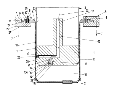
The sleeve 1 only shown in Fig. 1 has in cross-section a square
shape and is closed at one end (at the bottom in Fig. 1) by a lid
2 of synthetic plastics material, with no backing material. In
Fig. 1, the sleeve 1 is shown as partly pulled off the mandrel 3
by the scraper 4. The drawing shows the rear edge 5 of the sleeve
1 with which the gripper blocks 6 of the scraper generally desig-
nated 4 are engaged. The sleeve 1 moves in-the direction of its
longitudinal axis due to the translatory movement of the scraper
4 in its direction of translatory movement indicated by the arrow
7; firstly downwardly and subsequently by the same route back and
upwardly in the same diredction. This direction of movement or
conveyance 7 also coincides with the longitudinal axis 8 of the
lifting rod 9 shown in Figs. 2 and 3.
Firstly, it is intended to explain the mandrel 3 in greater
detail with reference to Fig. 1. In the direction of its longi-
tudinal axis which coincides with the direction of conveyance 7,
it consists of two serially disposed parts, namely the support-
ing part lO and the head part 11 by which the closed end face 12
is formed. This end face 12 is described as closed even though
an insert 13 is inserted by a screwed joint, the insert 13
-14-
1~33`~7~
consisting of a first inner portion 13a of a larger diameter and
an outer portion 13b of smaller diameter which is intended to be
connected directly to the former. The insert 13 may be in one
piece, its first part 13a carrying an external screwthread not
shown here but by means of which the insert 13 is fixed~in a bore
14, although other fixing possibilities such as, for example, a
press fit, tongue-and-groove, etc., are possible. While the
diameter of the bore 14 corresponds to the diameter of the larger
first part 13a, the diameter 13b of the second part of the insert
13 is reduced by twice the width of the circular gap 15, with the
result that due to the insert 13 in the bore 14 of relatively
large diameter, a circular gap 15 is formed, the width of which
is about 0.04 mm. This circular gap 15 forms the air outlet into
the space between the injection moulded lid 2 of synthetic plas-
tics material and the closed end face 12 of the mandrel, so that
withdrawal of the sleeve 1 in the direction of movement 7 cannot
result in any vacuum forming in the space designated 16.
The head part 11 of the mandrel 3 comprises a central rear pro-
jection 17 via which the head part 11 is mounted on the support-
ing part 10 of the mandrel 3 by a screwed connection, a slidingfit or similar fixing means.
The head part 11 is, from the side of its central projection 17,
provided with a first air passage 18 which is similarly construc-
ted like a blind bore in the same way as a second air passage 19
which is drilled from the outer periphery of the mandrel or its
head part and inwardly being closed on the outside by a plug 20.
This plug consists, for instance, of steel and has an external
screwthread which is screwed in airtight fashion into the head
part 11.
Starting from the second air passage 19 and substantially at
right-angles thereto extends the bore 14 into which the insert
13 is fitted, the bore 14 discharging transversely into the end
face 12 of the head part 11.
-15-
_ 13~3~78
Furthermore, the insert 13 carries a third air passage 21 which
communicates with the second air passage 19 in the head part 11,
being connected on the opposite side, in the smaller part 13b of
the insert 13, to a fourth air passage 22 which merges in from
the side. This fourth air passage merges on the outside into the
circular gap 14 so providing a gas flow connection from the first
to the fourth air passage 18, 19, 21, 22 and into the circular
gap 15, in fact by means of bores of relatively large diameter
which are quite straightforward from the production point of view.
It will be appreciated that also the supporting part 10 of the
mandrel 3 is provided with corresponding air supply means although
to simplify Fig. 1, they are not shawn in the drawings. If ref-
erence is merely made to them by stating that, at the upper end
of the middle portion 17 in Fig. 1, the curved arrow 23 indicates
the direction of air intake, which passes through the first air
passage 18, the second air passage 19, the third air passage 21
and the fourth air passage 22 and finally into the annular gap 15
and through it into the space 16 where the vacuum is dissipated
when the sleeve 1 is removed from the mandrel 3.
While the transporter means may be regarded as a horizontally
extending chain conveyor belt or such like, which is not shown
in the drawings, nevertheless Fig. 1 already shows the scraper
generally designated 4 which in plan view as shown in Fig. 3 is
V-shaped and comprises, constructed as an angle member, a carrier
24, from the inner edges 25 of which, a space is milled in order
to accommodate the gripper block 6, the space being closed from
underneath by the retaining plate 26. In Fig. 1, only the outer
contours of the retaining plate are identified by the broken
lines and the reference number 26. In Fig. 2, which is a view
of the apparatus according to the line II-II in Fig. 3, one sees
the retaining plate 26 with its last end piece. It is mounted
on the carrier 24 by means of screws 27. The broken lines 28
which extend lengthwise of the inner edges 25 in Fig. 3 show the
rear end of the milled-out space for accommodating the gripper
blocks 6. Braced against this rear wall 28 there is a centrally
-16-
13~30~8
disposed spring 29 which lies in-a cylindrical recess in the
gripper block 6, possibly being braced against the gripper block.
Thus, the gripper block is resiliently pretensioned, being
furthermore being fixed by guide pegs 30 provided on the carrier
24, so that the relevant guide journal 30 projects in each case
into an elongated hole 31, the longitudinal extension of which is
parallel with the central axis of the spring 29 and at right-
angles to the plane of the relevant inner edge 25. Thus, each
gripper block 6 is movable in relation to the inner edge 25 and,
in fact, in the case of the example of embodiment shown in the
drawings, it can be moved at right-angles thereto. From the out-
side, the spring 29 pushes the gripper block 6 inwardly beyond
the inner edge 25 and into the space formed by the arms of the V
of the inner edge 25. In operation, on the other hand, the man-
drel 3 which is not shown in Figs. 2 and 3, presses against the
force of the spring 29 and moves the gripper block 6 transversely
to the inner edge 25 and into the space (indicated by the broken
line 28 in Fig. 3) in the carrier 24, forcing together the springs
29. Due to this force and counterforce, the front edge 32 of the
gripper block 4 always rests against the flat surface of the man-
drel 3 therefore gripping, according to the top left view in Fig.
1, the rear edge 5 of the sleeve 1 reliably and with security
when the gripper block 6 is moved downwardly in the direction of
conveyance 7.
The translatory movement firstly in the direction of the arrow 7
in Fig. 1 downwardly in order to wipe the sleeve 1 off the man-
drel 3 and then back upwardly in the same direction in order to
move the scraper 4 back to its starting position (in Fig. 1 this
is the topmost position, not shown) takes place via the driven
lifting rod 9 which is moved upwardly and downwardly via drive
levers not shown in greater detail, in the direction of its
longitudinal axis 8. The lifting rod 9 runs thereby within the
fixing 34 provided on the table 33, in the sleeve 35 which is
shown in the centre upwards in order to illustrate the sliding
bearing 36 and the seal 37.
-17-
133~
Fig. 1 furthermore shows at the periphery of the mandrel 3 in the
region of its closed end face the bead-like widened-out portion
38 with which the closing edge is formed towards the sleeve 1
when this is pushed into its end position, not shown, in which
the mandrel 3 forms the inner shape against which there ~is
pressed and clamped a two-part outer mould which is not shown.
In operation, it is expedient to use a mandrel wheel provided
with four mandrels 3 which project outwardly from an axis of ro-
tation, the wheel rotating intermittently. A first mandrel 4
with a sleeve 1 is rotated into the starting position, not shown,
in which the longitudinal central axis of the mandrel 3 is in the
position shown in Fig. 1. In this position, the scraper 4 can be
moved upwardly into its topmost or starting position by the ex-
tension of the lifting rod 9 according to Fig. 2. The gripper 2
has its edge 32 (two grippers) bearing against the flat surface
of the mandrel 3. Now starts the downwards movement of the
lifting rod 9 in the direction of conveyance of the arrow 7.
The front edge 32 of the gripper block 16 grips two of the four
straight rear edges 5 of the sleeve 1 and moves it downwardly,
forming the space 16. Air is blown into this space through the
air passages 18, 19, 21, 22 and the circular gap 15 so that no
vacuum can be created and so that the sleeve 1 can be pulled
quickly down off the mandrel 3 while the lifting rod 9 moves into
the sleeve 35. While this is happening, the scraped-off paper
sleeve moves from the mandrel 3 into a transport basket disposed
at a distance from and below the mandrel 3,-in the direction of
conveyance 7, the transport basket being moved into the trans-
porter means. Now the extreme end position has been reached.
The drive reverses the movement of the lifting rod 9. The lift-
ing rod 9 now moves in the direction of its longitudinal axis 8
upwardly according to Fig. 2, i.e. against the direction of view
in Fig. 1. While this is happening, the mandrel wheel so rotates
in an anti-clockwise direction, when looking at Fig. 1, that the
free mandrel 3 continues to move rightwards and upwardly, while
-18-
,. ~ i- 1
-
l33~ia7~
a new mandrel 3 carrying a further paper sleeve 1 is rotated from
the left upwards into the position shown in Fig. 1. The fact
that while this is happening the scraper 4 with the V-shaped
angular carrier 25 is moved upwardly in the direction opposite
the direction of conveyance 7 does not interfere with attainment
of the starting position of the mandrel 3. Then the cycle begins
again.
Three sheets of drawings
--19--