Note: Descriptions are shown in the official language in which they were submitted.
1333331
RECREATIONAL BOAT SEAT/SUN DECK
Background of the Invention
The invention relates to recreational
boats, and, more particularly, to seats and sun decks
for such boats.
It is known to provide a recreational
boat with a seat that can be pivoted upwardly against
a generally vertical wall such as a transom wall.
Such a seat typically includes a seat bottom cushion
having a rearward end pivotally connected to the wall
by a conventional hinge apparatus. A disadvantage of
this construction is that the seat bottom cushion may
extend upwardly to an undesirable height (e.g., above
the top of the wall) when it is pivoted upwardly
against the wall.
It is also known to provide a seat back
cushion mounted on the wall above the seat bottom
cushion. The seat back cushion may prevent the seat
bottom cushion from being pivoted to a truly vertical
position.
Summary of the Invention
The invention provides a marine vehicle
comprising a generally vertical wall, a seat bottom
13333~1
--2--
member, and means supporting the seat bottom member
for movement between a first position wherein the
seat bottom member extends generally horizontally
from the wall and a second position wherein the seat
bottom member extends generally vertically against
and the wall, the supporting means including a
mounting member having first and second ends, means
connecting the first end of the mounting member to
the wall for pivotal movement about a first generally
horizontal axis, and means connecting the second end
of the mounting member to the seat bottom member for
pivotal ~v.~ -~t about a second axis generally
parallel to the first axis.
The invention also provides a marine
vehicle comprising a generally vertical wall, a seat
bottom member, and means supporting the seat bottom
member for v. -~t between a first position wherein
the seat bottom member extends generally horizontally
from the wall, and a second position wherein the seat
bottom member extends generally vertically against
the wall, which supporting means includes a mounting
member having first and second ends, means connecting
the first end of the mounting member to the wall for
pivotal movement about a first generally horizontal
axis, and means connecting the second end of the
mounting member to the seat bottom member for pivotal
movement about a second axis generally parallel to
the first axis, a retractahle leg for supporting the
seat bottom member in the first position, and a seat
. . .. .
,
-2A- 1333351
back member mounted on the wall and located between
the seat bottom member and the wall when the seat
bottom member is in the second position.
The invention also provides a marine
vehicle comprising a generally vertical wall, a seat
bottom member, and means supporting the seat bottom
member for movement between a first position wherein
the seat bottom member extends generally horizontally
from the wall, and a second position wherein the seat
bottom member extends generally vertically against
the wall, which supporting means includes a mounting
member having first and second ends, a mounting block
fixedly secured to and extending outwardly from the
wall and having a thickness, means connecting the
first end of the mounting member to the mounting
block for pivotal movement about a first generally
horizontal axis, and means connecting the second end
of the mounting member to the seat bottom member for
pivotal movement about a second axis generally
parallel to the first axis, and a seat back member
mounted on the wall and located betweeen the seat
bottom member and the wall when the seat bottom
member is in the second position, which seat back
member has a thickness approximately equal to the
thickness of the mounting block.
The invention also provides a marine
vehicle comprising a generally vertical wall, a seat
bottom member having a forward end, means supporting
-2B-
1'~333~
the seat bottom member for movement between a first
position wherein the seat bottom member extends
generally horizontally from the wall, and a second
position wherein the seat bottom member extends
generally vertically against the wall, which
supporting means includes a mounting member having
first and second ends, means connecting the first end
of the mounting member to the wall for pivotal
-v~ -nt about a first generally horizontal axis,
means connecting the second end of the mounting
member to the seat bottom member for pivotal movement
about a second axis generally parallel to the first
axis, an extension member, and means supporting the
extension member for ~,v. -nt between an extended
position wherein the extension member is
substantially coplanar with the seat bottom member
and extends outwardly from the forward end of the
seat bottom member, and a retracted position wherein
the extension member is located beneath the forward
end of the seat bottom member when the seal bottom
member is in the first position.
The invention also provides a marine
vehicle comprising a generally vertical wall, a seat
bottom member, and means supporting the seat bottom
member for movement between a first position wherein
the seat bottom member extends generally horizontally
from the wall, and a second position wherein the seat
bottom member extends generally vertically against
-2C- 13333~
the wall, which supporting means includes a mounting
member having first and second ends, means connecting
the first end of the mounting member to the wall for
pivotal movement about a first generally horizontal
axis, means connecting the second end of the mounting
member to the seat bottom member for pivotal movement
about a second axis generally parallel to the first
axis, a second generally vertical wall extending
generally perpendicular to the first-mentioned wall,
a second seat bottom member, and means supporting the
second seat bottom member for movement between an
operating position wherein the second seat bottom
member extends generally horizontally from the second
wall and is generally coplanar with the first seat
bottom member when the first seat bottom member is in
the first position, and a storage position wherein
the second seat bottom member extends generally
vertically against the second wall.
The invention also provides a marine
vehicle comprising a generally vertical wall, a seat
bottom member having a forward end, means supporting
the seat bottom member for movement between a first
position wherein the seat bottom member extends
generally horizontally from the wall, and a second
position wherein the seat bottom member extends
generally vertically against the wall, an extension
member, and means supporting the extension member for
mo~ ~ t between an extended position wherein the
-2D- 13333~1
extension member is substantially coplanar with the
seat bottom member and extends outwardly from the
seat bottom member, and a retracted position wherein
the extension member is located beneath and in
generally coplanar relation to the seat bottom member
when the seat bottom member is in the second
position.
The invention also provides a marine
vehicle comprising a generally vertical wall, a seat
bottom member, means supporting the seat bottom
member for ,v~ ^nt between a first position wherein
the seat bottom member extends generally horizontally
from the wall, and a second position wherein the seat
bottom member extends generally vertically against
the wall, which supporting means includes a mounting
member having first and second ends, means connecting
the first end of the mounting member to the wall for
pivotal -,v. -nt about a first generally horizontal
axis, and means connecting the second end of the
mounting member to the seat bottom member for pivotal
,v~ ^nt about a second axis generally parallel to
the first axis, an extension member, and means
supporting the extension member for ,v~ nt between
an extended position wherein the extension member is
substantially coplanar with the seat bottom member
and extends outwardly from the forward end of the
seat bottom member, and a retracted position wherein
the extension member is located beneath and in
:
133~3~1
generally coplanar relation to the seat bottom member
when the seat bottom member is in the second
position.
The invention also provides a marine
vehicle comprising a first generally vertical wall, a
second generally vertical wall extending generally
perpendicular to the first wall, a first seat bottom
member, a second seat bottom member, means supporting
the first seat bottom member for mov. ?~t between a
first position wherein the first seat bottom member
extends generally horizontally from the first wall
and a second position wherein the first seat bottom
member extends generally vertically against the first
wall, and means supporting the second seat bottom
member for -,v~ ?nt between an operating position
wherein the second seat bottom member extends
generally horizontally from the Recond wall and is
generally coplanar with the first seat bottom member
when the first seat bottom member is in the first
position, and a storage position wherein the second
seat bottom member extends generally vertically
against the second wall.
The invention also provides a marine
vehicle comprising a generally vertical wall, a seat
bottom member having a forward end, means supporting
the seat bottom member for movement between a first
position wherein the seat bottom member extends
Ll~
-- 133~3~1
generally horizontally from the wall, and a second
position wherein the seat bottom member extends
generally vertically against the wall, an extension
member, and means supporting the extension member for
-/v.- -nt between an extended position wherein the
extension member is substantially coplanar with the
seat bottom member and extends outwardly from the
forward end of the seat bottom member, and a
retracted position wherein the extension member is
located beneath the forward end of the seat bottom
member.
The invention also provides a marine
vehicle comprising a generally vertical wall, a seat
bottom member having a forward end, means supporting
the seat bottom member for -v.- ?nt between a first
position wherein the seat bottom member extends
generally horizontally from the wall, and a second
position wherein the seat bottom member extends
generally vertically against the wall, an extension
member, and means supporting the extension member for
,v~..cnt between an extended position wherein the
extension member is substantially coplanar with the
seat bottom member and extends outwardly from the
forward end of the seat bottom member, and a
retracted position wherein the extension member is
located beneath the forward end of the seat bottom
member when the seat bottom member is in the first
position.
.., ,~,,, . ~,
--5--
1~33351
A principal feature of the invention is
the provision of supporting means including a
mounting member having first and second ends, means
connecting the first end of the mounting member to a
wall for pivotal movement about a generally
horizontal axis, and means connecting the second end
of the mounting member to a seat bottom cushion for
pivotal movement about a second axis generally
parallel to the first axis. This arrangement permits
the seat bottom cushion to be folded up against the
wall without having the cushion extend upwardly to an
undesirable height.
Another principal feature of the
invention is the provision of a mounting block
extending outwardly from the wall, the mounting block
having a thickness approximately equal to the
thickness of a seat back cushion mounted on the wall,
and the first end of the mounting member being
pivotally connected to the mounting block. This
arrangement permits the seat bottom cushion to be
pivoted to a truly vertical position while having the
seat back cushion between the seat bottom cushion and
the wall.
Another principal feature of the
invention is the provision of a second seat bottom
cushion and means supporting the second seat bottom
cushion for movement between a storage position
wherein the second seat bottom cushion extends
--6--
1333351
.
generally vertically against a second wall, and an
operating position wherein the second seat bottom
cushion extends generally horizontally from the
second wall and wherein the second seat bottom
cushion is generally coplanar with the first seat
bottom cushion when the first seat bottom cushion is
in the first position.
Another principal feature of the
invention is the provision of a seat bottom member
supported for movement between a first position
wherein the seat bottom member extends generally
horizontally from a wall, and a second position
wherein the seat bottom member extends generally
vertically against the wall, an extension member, and
means supporting the extension member for movement
between an extended position wherein the extension
member is substantially coplanar with the seat bottom
member and extends outwardly from the forward end of
the seat bottom member, and a retracted position
wherein the extension member is located beneath the
forward end of the seat bottom member. This
construction provides a seat that can be folded up
against a wall and can also be extended to serve as a
sun deck.
Other features and advantages of the
invention will become apparent to those skilled in
the art upon review of the following detailed
description, claims and drawings.
--7--
13333~
Description of the Drawings
Figure 1 is a top plan view of a
recreational boat including a seat apparatus
embodying the invention.
Figure 2 is an enlarged, partial plan
view of the seat apparatus.
Figure 3 is a view taken along line 3-3
in Figure 2.
Figure 4 is a view similar to Figure 3
and showing the seat apparatus extended.
Figure 5 is a view similar to Figure 3
and showing the seat apparatus folded up.
Figure 6 is a view taken along line 6-6
in Figure 5.
Figure 7 is a view taken along line 7-7
in Figure 2.
Figure 8 is a view similar to Figure 7 -
and showing the second seat bottom cushion folded up.
Figure 9 is a perspective view of the
underside of the second seat bottom cushion.
Figure 10 is a partial perspective view
of the underside of the first seat bottom cushion.
Before one embodiment of the invention
is explained in detail, it is to be understood that
the invention is not limited in its application to
the details of construction and the arrangements of
components set forth in the following description or
illustrated in the drawings. The invention is
-8- 13333~1
capable of other embodiments and of being practiced
or being carried out in various ways. Also, it is to
be understood that the phraseology and terminology
used herein is for the purpose of description and
should not be regarded as limiting.
Description of the Preferred Embodiment
A recreational boat or marine vehicle
10 embodying the invention is illustrated in the
drawings. As shown in Figures 1 and 2, the boat 10
comprises a transom platform 12, a seating area 14,
and a generally vertical transom wall 16 separating
the seating area 14 from the transom platform 12.
The transom wall 16 has therein an opening 18
affording access from the seating area 14 to the
transom platform 12. The boat 10 also comprises a
generally vertical second or side wall 20 extending
generally perpendicular to the transom wall 16 and
further defining the seating area 14.
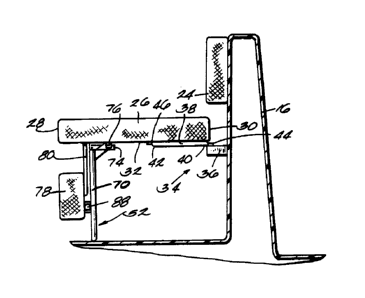
The boat 10 also comprises a seat
apparatus 22. The seat apparatus 22 comprises a seat
back member or cushion 24 mounted on the transom wall
16, and a first seat bottom member or cushion 26
having (see Fig. 3) forward and rearward ends 28 and
30, respectively, and an underside 32. The seat
apparatus 22 also comprises means 34 supporting the
seat bottom cushion 26 for movement between a first
or horizontal position wherein the seat bottom
- 9 -
1333351
cushion 26 extends generally horizontally from the
transom wall 16 and is below the seat back cushion
24, and a second or vertical position wherein the
seat bottom cushion 26 extends generally vertically
against the transom wall 16 with the seat back
cushion 24 between the seat bottom cushion 26 and the
transom wall 16. While various suitable supporting
means 34 can be employed, in the preferred
embodiment, the means 34 supporting the seat bottom
cushion 26 includes a mounting block 36 fixedly
secured to and extending outwardly from the transom
wall 16, the mounting block 36 having a thickness
approximately equal to the thickness of the seat back
cushion 24. The supporting means 34 also includes
(see Figs. 3 and 6) a mounting member or plate 38
having first and second ends, 40 and 42,
respectively, means connecting the first end 40 of
the mounting member 38 to the mounting block 36 (and
thus to the transom wall 16) for pivotal movement
about a first generally horizontal axis 44, and means
connecting the second end 42 of the mounting member
38 to the underside 32 of the seat bottom cushion 26
for pivotal movement about a second axis 46 generally
parallel to the first axis 44. Preferably, the first
end 40 of the mounting member 38 is pivotally
connected to the mounting block 36 by conventional
hinge apparatus 48 and the second end 42 of the
--10--
13333~1
mounting member 38 is pivotally connected to the seat
bottom cushion 26 by conventional hinge apparatus 50.
As shown in Figure 3, the mounting
plate 38 extends horizontally and the rearward end 30
of the seat bottom cushion 26 actually rests on top
of the mounting plate 38 when the seat bottom cushion
26 is in the first or horizontal position. Referring
to Figure 3, the seat bottom cushion 26 is moved from
the horizontal position to the vertical position by
rotating the seat bottom cushion 26 counterclockwise
relative to the mounting plate 38 and by rotating the
mounting plate 38 clockwise relative to the mounting
block 36. As shown in Figure 5, the mounting plate
38 extends generally vertically and the underside 32
of the seat bottom cushion 26 faces the underside of
the mounting plate when the seat bottom cushion 26 is
in the second or vertical position. Because the
thickness of the mounting block 36 is approximately
equal to the thickness of the seat back cushion 24,
the seat bottom cushion 26 is evenly spaced from the
the transom wall 16 by the mounting block 36 and by
the seat back cushion 24.
The apparatus 22 further comprises a -~
retractable leg 52 for supporting the seat bottom
cushion 26 in the first or horizontal position. In
the illustrated construction, as best shown in Figure
6, the leg 52 is generally W-shaped and is connected
to the underside 32 of the seat bottom cushion 26 for
133~51
pivotal movement relative thereto about a pivot axis
54 generally parallel to the first and second axes 44
and 46. The leg 52 includes a middle segment 56
extending along the pivot axis 54 and pivotally
connected to the seat bottom cushion 26 by a pair of
brackets 58. The leg 52 also includes a pair of
generally colinear, spaced-apart, first and second
deck-engaging segments, 60 and 62, respectively, a
first transverse segment 64 connected to the left end
(as shown in Figure 6) of the first deck-engaging
segment 60, a second transverse segment 66 connecting
the right end of the first deck-engaging segment 60
to the left end of the middle segment 56, a third
transverse segment 68 connecting the left end of the
second deck-engaging segment 62 to the right end of
the middle segment 56, and a forth transverse segment
70 connected to the right end of the second
deck-engaging segment 62. The upper ends (as shown
in Figure 6) of the first and fourth transverse
segments 64 and 70 are pivotally connected to the
underside 32 of the seat bottom cushion 26 by
suitable hinge apparatus 72 (Figs. 6 and 10).
The leg 52 is movable between a
retracted position (shown in Figures 5 and 6) and an
extended position (shown in Figures 3 and 4~. Means
are provided for securing the leg 52 in the extended
position. While various suitable means can be
employed, in the preferred embodiment, such means
-12-
13333~1
includes (see Figs. 3, 6 and 10) a perpendicular
extension 74 on the upper end of the fourth
transverse segment 70, and a clip 76 mounted on the
underside 32 of the seat bottom cushion 26 for
releasably securing the extension 74 against the
underside 32 of the seat bottom member 26.
The apparatus 22 also comprises an
extension cushion or member 78 having an underside
79, and means supporting the extension cushion 78 for
movement between an extended position (Figs. 4-6)
wherein the extension cushion 78 is substantially
coplanar with the seat bottom cushion 26 and extends
outwardly from the forward end 28 of the seat bottom
cushion 26, and a retracted position (Fig. 3) wherein
the extension cushion 78 is located beneath the
forward end 28 of the seat bottom cushion 26. While
various suitable means can be used for supporting the
extension cushion 78, in the preferred embodiment,
such means includes a plate 80 having a first end 82
fixed to the underside 79 of the extension cushion 78
and a second end 84 pivotally connected to the
underside 32 of the seat bottom cushion 26. As shown
in Figure 6, the plate 80 is preferably connected to
the underside 32 of the seat bottom cushion 26 by a
pair of hinge apparatus 86. The means supporting the
extension cushion 78 also includes a pair of
retractable legs 88 for supporting the extension
cushion 78 in the extended position. The legs 88 are
-13-
13~3351
shown retracted in Figures 3, 5 and 6 and are shown
extended in Figure 4.
When the extension cushion 78 is in its
extended position and the seat bottom cushion 26 is
in its first or horizontal position, as shown in Fig.
4, the seat bottom cushion 26 and the extension
cushion 78 form a sun deck. When the apparatus 22 is
to be used as a seat, the seat bottom cushion 26 is
placed in its horizontal position and the extension
cushion 78 is placed in its retracted position, as
shown in Figure 3. When the seat bottom cushion 26
is folded up, i.e., is moved to its second position,
the extension cushion 78 is moved to its extended
position, as shown in Figure 5.
The apparatus 22 further comprises (see
Figs. 1, 2 and 7-9) a second seat bottom cushion or
member 90 having an underside 92 and inner and outer
ends, 94 and 96, respectively, and means supporting
the second seat bottom cushion 90 for movement
between an operating position (Figs. 2 and 7) wherein
the second seat bottom cushion 90 extends generally
horizontally from the side wall 20 and is generally
coplanar with the first seat bottom cushion 26 when
the first seat bottom cushion 26 is in its first or
horizontal position, and a storage position (Fig. 8)
wherein the second seat bottom cushion 90 extends
generally vertically against the side wall 20.
--14--
1333351
While various suitable means can be
employed for supporting the second seat bottom
cushion 90, in the preferred embodiment, such means
includes a second mounting member or plate 98 having
first and second ends, 100 and 102, respectively,
means connecting the first end 100 of the second
mounting member 98 to the side wall 20 for pivotal
movement about a generally horizontal third axis 104,
and means connecting the second end 102 of the second
mounting plate 98 to the underside 92 of the second
seat bottom cushion 90 for pivotal movement about a
fourth axis 106 generally parallel to the third axis
104. As shown in Figures 7 and 8, the second
mounting plate 98 functions in a manner similar to
the first mounting plate 38. Additionally, the means
supporting the second seat bottom cushion 90 includes
a support bracket 108 (Figs. 2 and 7) mounted on the
underside 32 of the first seat bottom cushion 26 and
extending outwardly from the left side (as viewed in
Figure 2) of the first seat bottom cushion 26. The
outer end 96 of the second seat bottom cushion 90
rests on the support bracket 108 when the second seat
bottom cushion 90 is in its operating position, as
shown in Figure 7.
When the second seat bottom cushion 90
is in its operating position, as shown in Fig. 2, the
second seat bottom cushion 90 extends across the
access opening 18. When the first seat bottom
-15-
1333351
cushion 26 is in its horizontal position and the
second seat bottom cushion 90 is in its operating
position, the two cushions 26 and 90 form a
continuous seat extending across the seating area
14. The second seat bottom cushion 90 can be moved
to its storage position to afford access to the
opening 18 while the first seat bottom cushion 26 is
left in its horizontal position. Because the second
seat bottom cushion 90 is supported by the support
bracket 108 when the first seat bottom cushion 26 is
in its horizontal position, the second seat bottom
cushion 90 cannot be moved to its operating position
when the first seat bottom cushion 26 is not in its
horizontal position.
Various features of the invention are
set forth in the following claims.