Note: Descriptions are shown in the official language in which they were submitted.
1 333669
350R0091 OC
- 1 -
LIQUID PROPELLANT WEAPON SYSTEM
This is a divisional application of Canadian Application Serial No.
586,027, filed December 15, 1988.
Background of the Invention
1. Field of the Invention
This invention relates to weapon systems employing a liquid
prodellant, and particularly to such systems wherein the propellant is
progressively combusted aft of the projectile as the projectile advances
along the firing bore, i.e. a traveling charge system.
This invention also relates to such a system utilizing an initial source
of combustion gas to provide an initial acceleration to the projectile and
its traveling charge.
2. Prior Art
The classical propulsion of a projectile within the bore of a gun barrel
is limited in velocity by the need to accelerate the combustion gases to
-
1 333669
350R0091 OC
- 2 -
the velocity of the projectile. This results in an increasingly large fractionof the thermodynamic expansion work being expended on accelerating
the combustion gases. Normal ballistic models increase the apparent
mass of the pro;ectile by one-third the mass of the propellant. This
assumption accounts for the kinetic energy imparted to the gases. For
typical guns, the kinetic energy of the gases only amounts to about 10%
at a velocity of 1000 m./sec. At 2000 m.tsec. the fraction increases to
approximately 50%. As the velocity approaches 3,000 m./sec. the gas
kinetic energy approaches 100% (nothing left for the projectile.) This
effect produces what is called the "limit velocity" beyond which a
conventional gun propulsion system cannot operate. The Traveling
Charge Propulsion system provides a theoretical means around this limit.
As shown in FIGS 1 and 2, in a traveling charge propulsion system,
part or all of the charge C travels down the bore of the gun barrel with the
projectile P. Propulsion occurs by the rapid combustion of the charge in
the rear portion of the charge, sometimes called "cigarette burning". The
reference frame shown in FIG 1 is taken as moving with the projectile P,
wherein
AgoRE = cross-sectional area of the bore
Lcp = length of charge of propellant
Pp = densityofthe propellant
Pg = density of the combustion gas
1 333669
- 3 - 350R0091 OC
A = acceleration of the projectile
M = burn rate of the propellant [slugs/sec]
PBASE = pressure at the base of the projectile
PL = pressure at the interface of the
propellant and the combustion gas
Pw = pressure at the exit of the combustion
zone
r = linear burn rate of the propellant
Vj = exhaust velocity of the combustion gas
at the exit of the combustion zone
The accelerating force on the projectile and the traveling charge is
made up of two terms. The first term can be referred to as the "pressure"
term, where the combustion of the charge produces an elevated pressure
at the exit of the combustion zone. The second term can be referred to as
the "thrust" term, where the thrust is the result of the momentum of the
combustion gas exiting the combustion zone:
mV
PL = Pw +
ABORE
Both of these terms increase as the rate of combustion increases.
The total thrust divided by the mass consumption rate is referred to as
the"specific impulse" (a rocket term). It can be shown that this
parameter is a maximum when the gas velocity is greatest. Since this
combustion is taking place in a constant area duct (Rayleigh flow) the
1 333669
350R00910C
- 4 -
maximum velocity is the sonic velocity. Under these conditions, typically200 pounds of total thrust is generated for each pound of propellant
consumed per second. For a 30mm weapon to produce 50,000 Ibs. of
thrust, a consumption rate of 250 Ib./sec. is required. This consumption
rate requires a linear burn rate of approximately 300 ft./sec. Since normal
solid propellants only burn at approximately 1 foot per second at gun
pressures, it is apparent why the concept of solid propellant traveling
charge propulsion has yet to be made workable.
The use of liquid propellant for a traveling charge system has been
proposed previously.
In U.S. Patent 4,011,817, issued March 15, 1977, E. Ashley
disclosed a system which utilized the difference in density between the
combustion gases and the charge of liquid propellant as the source of
energy for the injection of propellant into the combustion chamber. A
primer provided the initial acceleration of a cavity generator. A charge of
liquid propellant aft of the projectile flowed relatively aftwardly past the
cavity generator into the combustion chamber which was formed by and
was aft of the cavity generator. The velocity provided by the primer was
in the order of hundreds of feet per second.
In Canadian Application Serial No. 399,900 filed March 31, 1982,
M.J.Bulman disclosed another system which utilized liquid propellant to
provide a traveling charge to a projectile.
The major drawback to the liquid propellant bulk loaded approach as
disclosed, for example, in U.S. Patent 4,085,653, issued to D.P. Tassie et
al on April 25, 1978, is poor control over combustion. The combustion in
a bulk loaded gun is largely the result of the growth of fluid dynamic
instabilities. A large burning rate is required before there is any
acceleration of the projectile and this amplifies any variations in the
ignition system.
1 333669
.
350R0091 OC
- 5 -
FIG 3A shows a typical bulk loaded liquid propellant Gun prior toignition. The cylindrical chamber is completely filled with liquid propellant.
The forward end of the chamber is closed by the base of the projectile.
The projectile is seated in the forcing cone of the barrel. The rear of the
chamber is closed by a bolt containing the igniter. When the igniter is
energized, a jet of hot gases emerges from the igniter vent (see FIG 3B).
This jet, as it enters the chamber must displace propellant in the chamber.
Since the chamber is initially constant in volume, this displaced propellant
must compress the remaining liquid. Even a small compression will
produce a large pressure rise in the liquid. For example, if the igniter jet
occupies 1% of the chamber volume, a pressure rise of several thousand
pounds per square results. Ignition of the main charge of liquid propellant
occurs on the surface of this expanding bubble of hot igniter gases. The
projectile starts moving when the gas bubble has grown to no more than a
few percent of the chamber volume with a nominal surface area which is
less than the area of the base of the projectile. In order to sustain a rising
pressure in the face of the rapid acceleration of the projectile, the actual
burning surface must be 100-1000 times the nominal value. This is
achieved in the bulk loaded cycle by the violent interaction between the
igniter jet and the liquid propellant. The shearing of the liquid surface by
the penetration of the igniter jet produces a rough surface akin to ocean
waves on a windy day (the Helmholtz instability - see FIGS 3C and 3D). If
insufficient surface area is generated, projectile forward motion will result
in a declining pressure and very poor performance. If too much surface
area is generated, dangerously high levels of pressure will occur. Since
the surface area generation is the result of great amplification in these
fluid mechanical instabilities, slight variations in any part of the process
will have a major impact on the pressure generated.
To illustrate the sensitivity to variations in the process, it can be
shown that combustion of only 1% of the charge before projectile forward
motion can produce a pressure rise in excess of 100,000 PSI (which is
often seen). FIG 4 shows a typical bulk loaded pressure time curve.
1 333669
350R0091 OC
- 6 -
Accordingly, it is an object of this invention to provide a bulk loaded,liquid propellant gun system having controlled ignition and combustion
which provide an improved traveling charge to propel the projectile.
Another object is to provide a liquid propellant gun system with an
improved control over ignition and combustion which avoids the strong
feedback present in the conventional bulk loaded cycle.
A feature of this invention is the provision of a liquid propellant gun
system having a traveling charge which is ignited after both such charge
and the projectile have been accelerated forwardly.
Brief Description of the Drawin~
These and other objects, advantages and features of the invention
will be apparent from the following specification thereof taken in
conjunction with the accompanying drawing in which:
FIG 1 is a schematic of a generalized traveling charge system;
FIG 2 is a chart of the velocity and pressure along the length of the
system of FIG 1;
FIG 3A is a schematic of a generalized bulk loaded liquid propellant
system prior to ignition;
FIG 3B is a detail of the system of FIG 3A showing the development
of the igniter jet;
FIG 3C is a detail of the system of FIG 3A showing the conversion of
the igniter jet into the combustion gas bubble;
FIG 3D is a detail of FIG 3A showing the liquid-gas interface;
FIG 4 is a chart showing time versus pressure of a firing of a typical
bulk loaded liquid propellant system;
1 333669
350 R00910C
-7-
FIG 5 is a view in longitudinal cross section of liquid propellantsystem embodying a first species of this invention, showing an
intermediate stage of the insertion of the projectile by the gun bolt;
FIG 6 is a view similar to FIG 5 showing the completion of the
insertion of the projectile by the gun bolt and the commencement of the
insertion of the liquid propellant;
FIG 7 is a view similar to FIG 5 showing the completion of the
insertion of the liquid propellant, the projectile rammed forward and the
bolt locked aft;
FIG 8 is a view similar to FIG 5 showing the commencement of
ignition;
FIG 9 is a view similar to FIG 5 showing the regenerative injection
stage of combustion;
FIG 10is a view similar to FIG 5 showing the transfer to the traveling
charge stage of combustion after the initial acceleration of the projectile
and the charge immediately aft of the projectile;
FIG 11 is a view similar to FIG 5 showing the traveling charge stage
after further acceleration of the projectile;
FIG 12A is a schematic of a stabilized Taylor Cavity;
FIG 12B is a detail of the schematic of FIG 12A showing the
gas/liquid interface of the cavity;
FIG 12C is a schematic similar to FIG 12A comparing a slow burning
cavity with a fast burning cavity;
FIG 13A is a view in longitudinal cross-section of hybrid solid and
liquid propellant system embodying a second species of this invention,
chambered and prior to ignition;
1 333669 350R00910C
FIG 1 3B is a schematic of the system of FIG 1 3A during the traveling
charge stage of operation;
FIG 14 is a view in longitudinal cross-section of liquid propellant
system utilizing a cavity generator embodying a third species of this
invention;
FIG 15 is a view of a fourth species of this invention; and
FIG 16 is a view of a fifth species of this invention.
Description of The Embodiment
The characteristics of a traveling charge propulsion system include:
1. Transport (i.e. traveling) of a charge of propellant forwardly along
the gun barrel bore (i.e. down-bore) with the projectile, with the
combustion of the charge of propellant providing additional acceleration
to the combined mass of the charge of propellant and the projectile.
2. Modification of the conventional down-bore gradient in pressure
by the combustion of the traveling charge of propellant.
3. Enhancement of performance compared to the propulsion
provided by a conventional system using an equivalent charge of
propellant.
These characteristics have already been demonstrated by the
system disclosed in the aforementioned Canadian Application Serial No.
399,990. In certain embodiments of that system the projectile is
incorporated into a sabot, which sabot adds its weight to the accelerated
mass. This invention avoids such an added weight.
This invention may be denominated the Fractional Traveling Charge
[FTCj propulsion system. In the FTC system, a bulk loaded liquid
propellant traveling charge and the respective projectile are both provided
with an initial acceleration and the charge is not ignited until both the
1 333669 350R00910C
charge and projectile have achieved significant velocity. This delayed
ignition provides two benefits:
1. Propulsion efficiency is improved by increasing the magnitude of
the velocity range through which the traveling charges operates.
2. The delayed ignition avoids the instabilities encountered in the
conventional ignition of a confined stationary charge.
The initial acceleration of the combined masses of the traveling
charge and the projectile can be provided by any convenient means. For
examples, an initial charge of solid propellant, or an initial charge of liquid
propellant. If liquid propellant is chosen, it may be utilized in a
regenerative injection liquid propellant combuster built into the overall gun
system. This combuster is made of a size adequate to accelerate the
combined masses of both the traveling charge and the projectile to a
velocity of approximately 1 km/sec before ignition of the traveling charge.
This requires the volume of the initial charge to be of the same order of
magnitude as the volume of the traveling charge. (The traveling charge
will normally be between 1/3 and 2/3 of the total charge depending on the
performance level of the gun system.)
A first embodiment of this invention is shown in FIGS 5 through 12.
This first embodiment is a gun having a totally integrated, two stage
propulsion system incorporating a regeneratively injected first stage and a
traveling charge second stage.
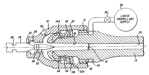
The gun includes a breech 10 which is fixed, as by mutual threads
12, to a gun barrel 14. The barrel has an aft chamber 16, an intermediate
forcing cone 18, and a forward, not necessarily rifled, bore 20. The
breech 10 has an aperture 22 which may be closed by a gun bolt 24
having a truncated cone forward portion. The breech has a groove 26
and the bolt has a groove 28 which may mutually receive a guillotine type
lock 30 to lock the bolt to the breech. Alternatively, a cam controlled iris-
slide of the type disclosed in U.S. Patent 3,772,959, issued November 20,
1 333669
350R0091 OC
- 10-
1973 to D.P. Tassie, may be utilized. An annular fill valve slide 32 istelescopically journaled on the breech end portion 14A of the barrel 14,
and an annular regenerative piston 34 is telescopically journaled on the
slide 32. Substantially as disclosed in Canadian Application Serial No.
399,899 filed March 31, 1982 - M.J. Bulman, liquid propellant may be
provided into the gun from a supply 36, through a fill valve 38, through
manifold 40, through a plurality of bores 42, through a manifold 44, and
through a plurality of longitudinal bores 48. An ignition device 50, of the
type disclosed in the aforementioned Canadian Application Serial No.
399,899 may be mounted through the breech 10.
FIG 5 shows the loading of a projectile 52, having a driving band 54;
through the aperture 22 by the gun bolt 24.
FIG 6 shows the bolt advancing forwardly and ramming the projectile
into the chamber 16. The fill valve 38 opens to admit liquid propellant
under pressure from the supply 36, through the manifold 40 and the bores
42, displacing the slide 32 and the piston 34 aftwardly, through the
manifold 44 and the bores 48 and through the interface gap between the
aft face of the portion 14A and the forward face of the head of the fill
valve slide 32 into the cavity defined between the projectile 52 and the
forward end of the gun bolt 24. The size of the gap is limited by a flange
32A on the valve 32 abuting a step 10A in the breech.
FIG 7 shows the flow of propellant displacing the projectile forwardly
in the chamber 16 to lodge the band 54 against the forcing cone 18; and
displacing the regenerative piston 34 aft. The bolt 24 is displaced
aftwardly and is locked to the breech 10 by the guillotine lock 30.
Thereafter, the valve 38 is closed.
FIG 8 shows the gun ready to fire. The traveling charge is that
volume of liquid propellant substantially contained within the chamber 16
aft of the projectile. The stationary (or initial) charge is that volume of
liquid propellant substantially contained between the head of the
regenerative piston 34 and the head of the fill valve slide 32.
1 3 3 3 6 6 9 350R00910C
- 11 -
FIG 9 shows the gun after ignition, provided by the ignition device
50, which has generated combustion gas in the combustion chamber 56
aft of the head of the regenerative piston 34, to push the piston forwardly
against the initial charge contained between the heads, to generate
increasing pressure in the stationary charge and the traveling charge.
Further, as the head of the piston moves forwardly away from the cone of
the gun bolt head it opens up an annular gap 56A which serves as
injection port for propellant to flow aftwardly into the combustion chamber
56. This regenerative injection is a result of the forward face of the head
of the piston 34 having a smaller transverse cross-sectional area than the
aft face of the head, to provide a differential, forwardly directed force on
the head. This differential force generates a high pressure on the
stationary charge which flows aftwardly, through the injection port 56A
into the combustion chamber 56 to sustain, or to increase, the combustion
gas pressure. When the pressure on the traveling charge exceeds the
shot start pressure (i.e. the pressure to engrave the band 54) the traveling
charge and the projectile begin to accelerate past the forcing cone and
beyond under the hydraulic influence of the regenerative first stage. The
two volumes fore and aft of the head of the piston 34 and the gap 56A
interconnecting them may be considered a complex, self feeding, self
limiting, combustion engine, i.e., a means for providing combustion.
FIG 10 shows the head of the piston 34 near the end of its forward
stroke towards the head of the fill valve slide 32. The piston is
decelerated by the flow exit area resulting from its shape and closing
proximity to the head of the slide. This deceleration reduces the rate of
flow of propellant from the stationary charge into the chamber 16 to cause
the pressure in the volume of liquid propellant in the chamber 16 to fall
below the pressure in the volume of combustion gas in the combustion
chamber 56. This pressure differential permits the combustion gases to
flow forwardly from the combustion chamber 56 through the injection port
56A into the chamber 16 to form an initial cavity 58 in the aft face of the
volume of the traveling charge of liquid propellant in the chamber 16.
FIG 11 shows the initial cavity advancing rapidly forwardly (down-
bore) as the regenerative injection stage ceases and the demand for
1 3 3 3 6 6 9 350R0091 OC
- 12 -
forward flow of liquid propellant by the accelerating projectile continues.This arrangement provides an inherent delay in the start of the traveling
charge stage of operation.
FIG 12A shows the formation of a stabilized Taylor Cavity which
moves forwardly with and towards the projectile. Most of the combustion
occurs on the side of the cavity where the relative velocity between the
gas and the liquid is high, as shown in FIG 12B. Combustion here is
similar to the regenerative injection combustion. The combustion rate
adjusts to match the injection rate as shown in FIG 12C. This quasi-
injection is seen in the thin sheet of liquid trailing behind the main part of
the cavity. If combustion is too fast, the sheet burns out sooner, reducing
the combustion surface area and the burn rate. If the burn rate is too
slow, the sheet trails further behind the cavity, increasing its burning
surface until equilibrium is achieved. Within the combustion zone,
moving aftwardly from the gas-liquid interface, the velocity of the
combustion gas increases and the pressure of the combustion gas
decreases.
It may be noted that this integrated system provides an inherent
delay in the ignition of the traveling charge since such ignition can not
begin until after the substantial completion of the combustion of the initial,
stationary charge.
The resultant traveling charge propellant burn rate therefore is
controlled by the velocity of the cavity toward the projectile as they both
move down-bore thus:
m = PL ABORE c
Where: m = mass burn rate#/sec.
PL = propellant density #ffl3
AgoRE = Bore area ft2
Vc = Cavity Penetration Velocity
1 333569
350R0091 OC
- 13-
The cavity advances into the traveling charge due to the buoyant
force (Fg) acting on it:
FB = 4/6 ~ SF D3goRE (PL - PG ) A
Where: A = Acceleration (G's)
PG = Gas Density
DBORE = Bore Dia (ft)
SF = shape factor (cavity volume compared to a
sphere of Bore dia)
The motion of the cavity is resisted by the fluid as if it were a solid
body. This drag force is:
D = 1/8 9 PL CD ~ D2B0RE Vc2
Where: CD = Drag Coefficient
Setting these forces equal allows us to solve for the penetration
velocity of the cavity:
89 SF DB0RE ( PL ~ PG ) A
Vc2
6 PL CD
This can be simplified by recognizing that PL ~ PG and combining
the constants:
Vc = K ~¦ DBORE A
~ 3336~9
350R0091 OC
- 14-
The acceleration of the projectile and traveling charge mass is
obtained from:
P A
A = B BORE
(MB + TC)
Where: PB = Base Pressure
MB = Projectile Mass (#)
TC = Traveling Charge Mass (#)
If we assume base pressure is to be the same for all guns and we
scale the projectile and traveling charge masses by (DBoRE)3 we get:
PB
A Oc
DBORE
Thus Vc is independent of scale.
If the burn rate is high enough, the base pressure is only a function
of the burn rate thus:
PB
ABORE
Where: F = Total thrust
m Isp
lSp = Specific Impulse # sec/#
-- 1 3 3 3 6 6 9 350R0091 OC
- 15-
acceleration now beco",es:
A - m ISp / ~MB + TC)
PL A~E ISP Vc
(MB + TC)
(I~B TC) R ~ DBOR}: A
A . n PL D Ba~E 2
16 (MB + TC)
remembering that (MB + TC) = C D3BoRE~ we get:
n2 pL2 ISp2 R2
A ~ 2
16 C DBORE
or again:
A c~
DBORE
The constants in these relationships may change with caliber but the
principal effects scale in an acceptable way.
A second embodiment of this invention is shown in FIGS 13A and
1 3B. This embodiment is a gun having a solid propellant first stage and a
liquid propellant second stage. Such a system may be referred to as a
Hybrid Traveling Charge (HTC) propulsion system.
- 1 333669
350R00910C
- 16-
FIG 13A shows a gun having a breech 100 with a chamber 102and a gun barrel 104 with a bore 106, and a gun bolt 108 with a firing pin
110. A telescoped round of ammunition 112 is disposed in the chamber
102 which is closed by the gun bolt 108.
The round of ammunition comprises a case 114 with a main portion
115, a forward, tubular, return bend 116 providing a sleeve portion 118,
and a base portion 120 with a bore 122 in which is fixed a primer 124.
The outer diameter of the main portion 115 matches the inner diameter of
the chamber 102. The inner diameter of the sleeve portion 118 matches
the inner diameter of the bore 106. A sabot 126 with a projectile 128 is
disposed in the forward portion of the sleeve portion 118. A cavity
generator 130 is disposed in the aft portion of the sleeve portion 118. A
charge 131 of liquid propellant is disposed in the sleeve portion forward of
the generator and around the aft portion of the sabot. The intermediate
portion of the sabot has an annular seal 132, and the forward portion of
the sabot has a bore rider 134. The cavity generator 130 is also sealed to
the sleeve, all to seal the charge of liquid propellant within the case 114.
The interior volume between the sleeve portion 118 and the main portion
115 and the base portion 120 of the case is filled with a charge 137 of
solid propellant (which may be consolidated to improve the packing
efficiency).
The propulsion operation begins with the energization of the primer
124 by the firing pin 110 to ignite the solid propellant 137. As the
pressure developed by the combustion gas rises, the gas pushes, i.e.
accelerates the cavity generator 130, the sabot 126 with its projectile 128,
and the captured charge of liquid propellant 131 forwardly, as a unit, into
the gun bore 106.
As previously stated, a traveling charge provides improved
performance when the ignition of such traveling charge is delayed until
the projectile and such charge have achieved significant velocity. In this
species, the cavity generator 130 serves to provide the necessary delay.
1 333669
350R00910C
The cavity generator, prior to firing, serves to seal the rear of the liquid
propellant traveling charge 131 within the case 114. After ignition of the
stationary charge of solid propellant 137 and prior to the ignition of the
traveling charge of liquid propellant, the generator 130 serves to isolate
the traveling charge 131 from the combustion gases generated by the
stationary charge 137. The generator 130 has a plurality of longitudinal
bores 136, each extending from a substantially flat transverse front face
140 to a substantially concave transverse aft face 142, so that the bores
vary in length. These bores 136 are obturated respectively with a
material 136A which has a density different from the density of the
generator 130 and which is resistant to movement, e.g. grease or press-
fitted pins. During the initial acceleration of the generator 130, this
material does obturate the bores 136. The acceleration forces acting on
this material serve to extrude the material forward or aftward from the
generator depending on their relative densities. After a period of time
during this period of initial acceleration, due to the combustion of the
stationary charge 137, these bores 136 are thus sequentially opened in
reverse order of their respective lengths. As shown in FIG 13B, as these
bores are opened, hot combustion gases pass forwardly through the
bores to the rear face of the traveling charge of liquid propellant 131 to
form an initial cavity 144 whose shape is substantially determined by the
sequence in which the bores 136 open. The shortest bores in the center
of the generator pass the gas first to form the deepest part of the cavity.
Once formed, this initial cavity takes the shape of a stabilized Taylor
Cavity as discussed with respect to FIG 12A.
FIG 14 shows a third embodiment of this invention. This
embodiment is a gun which combines features of the first and second
embodiments of this invention. The system includes a liquid propellant,
regenerative injection, first stage, a liquid propellant, traveling charge,
second stage, and a cavity generator to provide a delay prior to the
ignition of the second stage.
1 333669
350R00910C
- 18-
This gun is similar to that shown by M. J. Bulman in Cdn. S.N.399,899 filed March 31, 1982 and includes a breech 200, to which is
secured a gun barrel 202 having a bore 204. The gun barrel has an
aftwardly projecting extension 206 on which is telescopically journaled an
annular fill valve 208 having a head portion 210 and a tail portion 212.
Telescopically journaled on the fill valve is an annular, regenerative
piston 214 having a head portion 216 and a tail portion 218. A supply
220 of liquid propellant under pressure is coupled via an inlet valve 222 to
a manifold 224 which communicates with an annular row of longitudinal
bores 226 through the barrel extension 206. The bores 226 may be
obturated by a snap-action valve 228 (e.g., a belleville washer) and
otherwise communicate with an annular row of longitudinal bores 230
through the fill valve head portion 210. When the fill valve is in its
forwardmost disposition its head portion is seated on the snap-action
valve 228 to obturate the bores 226. when the regenerative piston is in its
aftmost disposition, the inner rim 216A of its head portion is seated on an
annular projection 202A of the barrel to define a pumping chamber 232
between the fill valve head portion and the regenerative piston head
portion. Two annular rows 234 and 236 of radial bores through the barrel
extension communicate between the pumping chamber 232 and the gun
barrel bore 204.
The aft end of the breech has an opening 238 which is closed by a
gun bolt 240 whose head rotates about its longitudinal axis to lock and
unlock. The face of the bolt has a pair of extraction lugs 242 to engage
the extractor rim 244 of a stub case 246 which carries a booster cartridge
248. The case has a primer 250 opening onto a conduit which leads to a
booster charge 252 opening onto a plurality of radial bores 254, which
open onto a combustion chamber 255 defined by the breech 200, the
piston head 216, the barrel extension 206, and the cartridge 248. The
gun bolt has a firing pin 256 to actuate the primer 250.
In loading the gun, the gun bolt may be withdrawn and a projectile,
here shown as a rod penetrator 257A with fins carried in a sabot 257B,
1 333669
350R00910C
- 19-
may be inserted. Subsequently a cavity generator 258A with a plurality ofbores 258B, extending from a planar front face 260 to a concave aft face
262, and filled with an obturating medium, may be inserted. The front
face may have an annular bevel 264, which when aligned with the bores
234 provides ~ccess from the pumping chamber 232 to the interface
between the cavity generator and the projectile. Thereafter, the gunbolt,
carrying a stubcase with a booster cartridge, is inserted into the breech
opening and locked. The annular piston 214 may be in its aftmost
position, with the surface 216A on the projection 202A. The annular fill
valve may be in a forward disposition. The inlet valve 222 is opened to
admit liquid propellant from the supply 220 under pressure into the
manifold 224, through the bores 226, past the snap action valve 228,
through the bores 230, into the pumping chamber 232, through the bores
234, into the interface between the cavity generator and the projectile,
pushing the projectile forwardly until it is halted by the forcing cone 204A
in the bore 204. An interface gap is provided between the forward face of
the booster cartridge and the aft face of the cavity generator by suitable
means, such as conical ridges on the booster face.
Upon ignition of the primer 250, hot gases are provided to ignite
the booster charge 252 which in turn vents combustion gas through the
bores 254 into the combustion chamber 255. The pressure of the
combustion gas in the combustion chamber acts on the aft face of the
differential piston head 216 to displace the piston 214 forwardly, and
through the medium of the liquid propellant and bore 230 to close the
snap action valve 228 to close the bores 226 and isolate the liquid
propellant supply system from the pumping chamber. As the annulus
216A of the head 216 moves off the annulus 20~A of the barrel extension
206, a progressively increasing annular gap or injection port is thereby
provided through which liquid propellant is injected from the pumping
chamber 232 into the combustion chamber 255.
1 333669
350R00910C
- 20 -
Combustion gas passes into the interface gap between the cavitygenerator and the booster and acts on the aft face of the cavity generator
to displace the cavity generator forwardly to close off the bores 234 and
through the medium of the liquid propellant in the bore to displace the
sabot with its projectile past the forcing cone 204A. In due course the
assembly of cavity generator, traveling charge of liquid propellant and
sabot and projectile is accelerated forwardly along the gun barrel bore
204.
When the cavity generator is forward of and clears the bores 234
and 236, liquid propellant is then pumped through these bores from the
pumping chamber into the combustion chamber which now extends into
the aft portion of the bore 204.
In due course all of the liquid propellant in the combustion chamber
255 and in the aft end of the gun barrel bore aft of the cavity chamber has
combusted and the combustion gas generated thereby continues to
expand and to accelerate the assembly. At this time the obturating
medium is displaced from the bores 258B initially from the shorter, inner
bores and subsequently from the longer outer bores, to permit combustion
gas to flow therethrough and to form a bubble of combustion gas at the
forward face of the cavity generator. This bubble ignites the aft face of
the traveling charge of liquid propellant and develops into a Taylor cavity
as previously described.
FIG. 15 shows a fourth embodiment of this invention. This
embodiment is the most elemental embodiment of this invention
comprising two combustion chambers. The system includes a liquid
propellant, stationary combustion chamber and cavity generator and a
liquid propellant, traveling combustion chamber.
This gun includes a breech 300 to which is secured a gun barrel
302 having a bore 304. The aft end of the breech has an opening 306
1 333669
350R00910C
-21 -
which is closed by a gun bolt 308 which is locked and unlocked to thebreech by suitable means such as a movable lug 310 journaled to the
breech to engage an annular lug 312 integral with the bolt. The forward
end of the bolt 308 is formed as a truncated cone which has a channel
310 cut into it with an under cut 312 to receive the aft end of a "hold-back"
or "shot-start" link 314. The forward end of the link is secured to the aft
end of a projectile 316 which is fitted into a sabot 318 which has an
annular seal 320.
An annular combustion chamber 330, coaxial with the gun barrel
bore 304, is provided in the breech. A supply 332 of liquid propellant
under pressure is coupled via an inlet valve 334 and a manifold to a pair
of diametrically opposed ignition systems. Each system includes a
unidirectional valve 336 to an ignition chamber 338 which has a spark
plug 340 and an outlet 342 coupled to the combustion chamber. The
combustion chamber has an annular outlet 344 having a conical shape
directed into and forwardly along the gun barrel bore 304.
A projectile and sabot may be placed on the gun bolt by means of
the link 314 and inserted through the aperture 306 into the gun barrel
bore 304. In case it is desired to withdraw the projectile, as in the case of
a misfire, the link 314 permited the gun bolt to provide this function also.
The link may be designed to rupture when the projectile is subjected to a
relatively high pressure, e.g., after ignition of the liquid propellant in the
combustion chamber 330. Alternatively, the link may be designed to
rupture at a relatively low pressure, e.g., upon inletting of liquid propellant
under low pressure into the gun barrel bore from the combustion
chamber. In this case, after rupture of the link, the inletted propellant
advances the projectile and sabot until the sabot is halted by the forcing
cone 304a in the bore.
In a preferred arrangement, an annular valve slide 350 is also
provided. This slide is coaxial with and receives the forward portion of the
1 333669
350R00910C
- 22 -
gun bolt and also forms the aft wall of the combustion chamber. The slideis normally biased forwardly by a plurality of springs 352 so that its
forwardly projecting lip 354, which forms the aft wall of an annular valve
outlet 344, abuts the forward wall of the outlet to close the outlet. The
springs are disposed in an annular pumping chamber 356 which is
coupled via a varialble orifice 358 and a unidirectional valve 360 to a
supply 362 of lubricant under pressure. The chamber 356 is coupled, via
an annular row of radial bores 364 through the slide, to an annular groove
366 in the gun bolt.
When liquid propellant is initially being pumped from the supply
332 into the pair of ignition chambers 338 and the annular combustion
chamber 330, the slide 350 is in its forwardmost disposition, closing the
valve outlet 344 of the combustion chamber. During this interval the gun
bolt may be completing its loading of the projectile and sabot into the gun
barrel bore and locking. When the combustion chamber is full of liquid
propellant under pressure, the liquid pressure forces the slide aftwardly,
against the bias of the springs 352, to open the annular outlet 344 to
permit the flow of liquid propellant from the combustion chamber into the
aft portion of the bore 304 up to the seal 320 on the sabot. This initial
aftward movement of the slide forces some of the lubricant from the
annular groove 356 into the interface between the gun bolt and the slide
to provide an initial volume of lubricant, which also serve as a seal
against combustion gas, in the interface. This seal is replenished during
each firing cycle of the gun.
After the pair of ignition chambers 338, the combustion chamber
330, and the volume of the gun barrel bore 304 forward of the gun bolt
and aft of the seal 320 have been filled with liquid propellant, the pair of
spark plugs 340 are energized to ignite the liquid propellant in the ignition
chambers. The pair of bubbles of combustion gas respectively enlarge
and ignite the liquid propellant in the combustion chamber. As the gas
1 333669
350R0091 OC
- 23 -
pressure builds up in the combustion chamber the slide 350 is forcedaftwardly to increase the volume of the combustion chamber from its initial
minimum volume to its maximum volume to slow down the rate of increase
in gas pressure. This final aftward movement of the slide also forces
more lubricant from the annular groove 366 into the interface between the
gun bolt and the slide. It will be seen that the seal between the gun bolt
and the slide is thus renewed for each firing of a round. The expanding
combustion gas flows through the valve outlet 344 and into the gun barrel
bore both (i) pushing the volume of liquid propellant therein and thereby
the projectile and sabot forwardly past the forcing cone and (ii) consuming
the aft face of that volume as a Taylor cavity. All of the charge of liquid
propellant in the stationary combustion chamber 330 should be
combusted before the traveling charge of liquid propellant in the gun
barrel bore aft of the seal 320 carried by the sabot is ignited so as to
control the peak pressure developed in the combustion system. As the
traveling charge progresses forwardly along the gun barrel bore that
portion of the bore in which it is disposed may be considered to be a
combustion chamber, ergo, the traveling charge is disposed in a traveling
combustion chamber.
As indicated earlier, the link 314 may be made stronger so that the
projectile is thereby held to the gun bolt throughout the period of filling
with propellant and after ignition until some desired pressure, such as
5,000 psi or higher is developed in the combustion system.
FIG. 16 shows a fifth embodiment of this invention. This
embodiment utilizes a technique for providing a two phase mixture of
droplets of liquid propellant and a gas for the first stage propulsion. This
technique is disclosed in United States Patent Number 4,050,348 which
issued September 27, 1977 to A. R. Graham.
The gun system includes a housing 400 which extends forwardly
into a gun barrel having a gun bore 402 and aftwardly into a breech
-
1 333669
350R00910C
- 24 -
having an opening 404 which is closed by a gun bolt 406. The gun boltmay have seals and an electrode 408 in an ignitor cavity as shown in
United States Patent Number 3,783,737 which patent issued January 8,
1974. A conduit 418, having a unidirectional valve 420, couples a supply
422 of gas, such as nitrogen or air, to the ignitor cavity. A spring 430
loaded piston 432 operates in the housing as a fill valve to couple a liquid
propellant fill system 434 via a valve 435 and a conduit 436 into the aft
end 438 of the gun bore.
When the gun bolt is withdrawn, an assembly, consisting of a
projectile 440 carried by a sabot 442 and a cavity generator 444 fixed to
the projectile by a frangible link 446, may be inserted into the aft end 438
of the bore so that the cavity generator is aft of the opening 436A of the
conduit 436 into the bore and the projectile is forward thereof. The gun
bolt is then inserted to a first position to back up the cavity generator.
The spring loaded piston 432 is moved aftwardly, to open the fill valve, by
applying liquid propellant under pressure from the liquid propellant
suppply 434. Liquid propellant then flows into the volume between the
cavity generator and the projectile. The ullage air contained therein is
compressed and the projectile urged forwardly until the frangible link is
broken. As liquid propellant continues to enter the volume the projectile
moves forwardly until the full metered charge is entered and the fill valve
closes. Aftward movement of the cavity generator is blocked by the gun
bolt. The valve 420 is now opened to admit gas under pressure from the
supply 422 into the igniter cavity and this gas acts on the aft face of the
cavity generator 444 to advance the train of generator, liquid propellant,
and projectile and sabot forwardly until the sabot is halted by the forcing
cone 450 in the gun barrel. When the gas flow pressure reaches a
predetermined level, the valve 420 is closed. A metered volume of liquid
propellant is again applied, under pressure greater than the gas pressure,
through the fill valve into the volume aft of the cavity generator. As the
liquid propellant flows into the gas under pressure, it is sheared into
1 3~3669
350R0091 OC
- 25 -
droplets. The gun bolt is then moved forwardly to compress the two
phase mixture of gas and droplets of liquid propellant, and then locked. A
voltage is applied to the electrode 408 to ignite the two phase mixture in
the ignition cavity and the ballistic cycle proceeds as discussed in the
other embodiments.