Note: Descriptions are shown in the official language in which they were submitted.
133378~
- 1 - 13LN 1862
METHOD AND APPARATUS FOR ELECTROCHEMICALLY
MACHINING AIRFOIL BLADES
BACKGROUND OF THE INVENTION
This invention relates generally to
eleetroehemieally maehining of metallie parts, and,
more speeifieally, to eleetroehemically machining
airfoils.
Eleetroehemieal maehining (hereinbelow also
referred to alternatively as simply machining) is a
conventional process in which a workpiece is typieally
provided with a positive voltage to ereate an anode,
and an eleetrode is provided with a negative voltage
to create a eathode. DC voltages between about 5-25
volts and up to about 15-30,000 amps are typieally
used. An eleetrolyte is then channeled in the space
or gap between the workpiece and the electrode for
eleetroehemieally maehining the workpieee. Sueh gas
must be aeeurately maintained to avoid damaging
sparking, or areing, whieh would occur with gaps which
are too small or eause too little electrolyte flow.
The prior art includes various methods for
electrochemically machining airfoil blades, either
singly or on a unitary integral bl(aded-d)isk
assembly, i.e. blisk. Leading and trailing edges of
an airfoil blade are especially diffieult to machine
preeisely, and the prior art teaehes various apparatus
therefor.
133~783
- 2 - 13LN 1862
Blisks having high camber high twist and/or
high solidity create substantial problems for
economically electrochemically machining blades
thereon. Camber refers to the angle of blade tip with
respect to a centerline axis. Twist refers to the
difference in camber angles between blade root and
blade tip. And solidity refers to the number of
blades with respect to the circumference of a blisk
with high solidity indicating relatively
closely-spaced blades.
An apparatus for efficiently and
economically electrochemically machining blisks,
therefore, must do so in relatively few operations and
without utilizing relatively complex structure.
OBJECTS OF THE INVENTION
Accordingly, an object of the present
invention is to provide a new and improved method and
apparatus for electrochemically machining an airfoil.
Another object of the present invention is
to provide a new and improved method and apparatus for
electrochemically machining a blisk.
Another object of the present invention is
to provide a new and improved method and apparatus for
electrochemically machining an airfoil in a single
operation from a workpiece blank.
Another object of the present invention is
to provide a new and improved method and apparatus for
precisely electrochemically machining both leading and
trailing edges of a workpiece blank in addition to the
surfaces therebetween.
Another object of the present invention is
to provide a new and improved method and apparatus for
electrochemically machining a platform between
adjacent blades on a blisk simultaneously with
electrochemically machining a blade thereon.
133~7g~
- 3 - 13LN 1862
SUMMARY OF THE INVENTION
In accordance with a preferred, exemplary
embodiment of the invention, a method of forming a
blisk from a workpiece is disclosed. The workpiece
includes a blank having oppositely facing first and
second faces defined by a radially inner base, a
radially outer top, a first edge, and a second edge.
The method comprises the steps of:
positioning first and second electrodes
adjacent to the first and second faces, respectively,
of the blank;
supplying a positive voltage to the blank
and a negative voltage to the first and second
electrodes;
channeling an electrolyte between the blank
and the first and second electrodes for
electrochemically machining the blank;
moving the first and second electrodes
toward the first and second faces of the blank; and
moving the workpiece toward the first and
second electrodes.
In accordance with another embodiment of the
invention, an apparatus is disclosed for practicing
the method.
In accordance with another embodiment of the
invention, a new and improved electrode pair is
disclosed for electrochemically machining an airfoil.
BRIEF DESCRIPTION OF THE DRAWINGS
The novel features believed characteristic
of the invention are set forth in the appended
claims. The invention, in accordance with preferred
and exemplary embodiments thereof, and including
additional objects and advantages, is more
particularly described in the following detailed
description taken in conjunction with the accompanying
1333783
- 4 - 13LN 1862
drawings in which:
Figure 1 is a perspective view of an
apparatus, in part schematic, including a machine for
electrochemical machining in accordance with a
preferred embodiment of the present invention.
Figure 2 is a plan view of a portion of the
electrochemical machine illustrated in Figure 1 in a
horizontal plane.
Figure 3 is a plan view of a portion of the
electrochemical machine illustrated in Figure 1 in a
vertical plane disposed normal to the horizontal plane
of Figure 2.
Figure 4 is a plan view of a portion of the
electrochemical machine illustrated in Figure 1 in a
second vertical plane normal to both the horizontal
plane of Figure 2 and the vertical plane of Figure 3.
Figure 5 is a perspective view of a portion
of a rough workpiece used for manufacturing a blisk.
Figure 6 is a perspective view of a roughing
electrode usable for electrochemically machining
blanks from the rough workpiece illustrated in
Figure 5.
Figure 7 is a sectional view of a portion of
the roughing electrode of Figure 6 and a portion of
the rough workpiece illustrated in Figure 5
illustrating electrochemical machining thereof.
Figure 8 is a perspective, partly sectional,
view of a portion of a blisk workpiece formed from the
rough workpiece illustrated in Figure 5.
Figure 9 is an elevation view of a portion
of a finally electrochemically machined blisk formed
from the workpiece illustrated in Figure 8.
Figure 10 illustrates front perspective
views of complementary electrodes usable for
electrochemically machining blisk blades in accordance
_ 5 _ 1333783 13LN 1862
with one embodiment of the invention.
Figure 11 illustrates back perspective views of
the electrodes illustrated in Figure 10.
Figure 12 is a top plan view of the electrodes
illustrated in Figures 10 and 11 in a machining position
over the workpiece of Figure 8, Figure 12 is found on the
sheet of drawings containing Figure 9.
Figure 13 is a side view of the electrode pair
illustrated in Figure 12 taken along line 13-13, Figure 13
is found on the sheet of drawings containing Figure 9.
Figure 14 is a sectional view in part through the
electrode pair illustrated in Figure 17 taken along line
14-14.
Figure 15 is a perspective view of the workpiece
12 positioned just prior to the entry of a workpiece blank
between the electrode pair illustrated in Figure 12.
Figure 16 is a perspective view of an electrolyte
outlet block taken along line 16-16 in Figure 12.
Figure 17 is a partly sectional view taken along
a centerline of the flowpath of electrolyte through the
electrode pair illustrated in Figure 12 taken along line
17-17.
Figure 18 is a sectional view of a portion of one
electrode and the workpiece blank illustrated in Figure 14
taken along line 18-18.
DETAILED DESCRIPTION
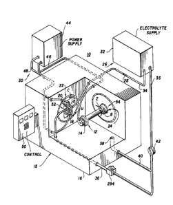
Illustrated in Figure 1 is an apparatus 10 for
electrochemically machining or forming a blisk from a
workpiece 12 having a plurality of circumferentially-
spaced workpiece blanks 14. The apparatus 10 includes anelectrochemical machine 15 having a housing 16, a pair of
electrodes including a first electrode 18 and a second
electrode 20, and means 22 for mounting the electrode pair to
the housing 16. Means 24 for mounting the workpiece 12 to
.
6 1 3 337 ~LN 1862
the housing 16 are also provided.
The apparatus 10 further includes means 26
for channeling electrolyte 28 to the electrode pair
and means 30 for powering the electrode pair with a
negative voltage and the workpiece 12 with a positive
voltage. The electrolyte 28 is conventional and may
include a solution of water and sodium chloride and/or
sodium nitrate, or other effective electrolyte
solution.
The electrolyte channeling means 26 includes
a conventional electrolyte supply 32, which provides
relatively clean and temperature controlled
electrolyte 28 to the electrode pair 18, 20 through a
supply conduit 34. The supply 32 is conventional and
includes, in part, a high pressure pump, in-line
filter, temperature controlling means and suitable
control valves (all not shown). A return conduit 36
receives the electrolyte 28 from the electrode pair
for return to the supply 32. A drain 38 formed in the
housing 16 is provided for capturing any electrolyte
28 which leaks and returning it to the supply 32
through a drain conduit 40 connected to the return
conduit 36. A conventional pump 42 is disposed in the
return conduit 36 for returning electrolyte 28 from
the electrode pair and the drain 38 to the supply 32.
The power means 30 includes a conventional
power supply 44 effective for providing DC power
between 5 and 25 volts and at up to 15,000 amperes.
Current up to 30,000 amperes could also be used for
machining relatively large workpieces 12. A positive
cable 46 connects the power supply 44 to the workpiece
12. A negative cable 48 connects the power supply 44
to both the first and second electrodes 18 and 20. A
negative voltage is supplied through the cable 48 to
the first and second electrodes 18 and 20, and a
133~
- 7 -- 13LN 1862
positive voltage is supplied through the cable 46 to
the workpiece 12.
The apparatus 10 further includes a
conventional control means 50 suitably connected to
and effective for electrically controlling the
electrode mounting means 22, the workpiece mounting
means 24, the power means 30 and the channeling means
26.
The electrode mounting means 22 provides
colinear translation of the electrode pair with
translation of the first electrode 18 occurring in a
U direction or axis, and translation of the second
electrode 20 occurring in an X direction or axis
parallel to the U direction. The means 22 also mounts
the electrode pair as described in more particularity
below for rotation in an annular C direction. A
conventional elastic seal 52 allows the mounting means
22 to translate the rotate while preventing the
electrolyte 28 from contacting the conventional
mechanisms providing for movement in the X, U, and C
directions. The seal 52 includes, for example,
bellows-like folds (not shown) for accommodating X and
U translation. And, at a radially outer perimeter
thereof, the seal 52 includes an annular sliding seal
for accommodating C rotation.
The workpiece mounting means 24, also more
particularly described hereinbelow, is effective for
translating the workpiece 12 in a Z direction or axis
and rotating the workpiece 12 in an annular B
direction. A conventional elastic seal 54 is provided
for allowing the mounting means 24 to translate and
rotate while preventing the electrolyte 28 from
contacting the conventional mechanisms of the mounting
means 24 in the housing 16. The seal 54 includes, for
example, bellows-like folds (not shown) for
1333783
- 8 - 13LN 1862
accommodating Z translation. An, at a radially inner
perimeter thereof, the seal 54 includes an annular
sliding seal for accommodating B rotation.
Figures 2-4 illustrate in more particularity
certain features of the housing 16. The electrode
mounting means 22 includes a first turntable 56
suitably attached to the housing 16 and rotatable in
the C direction about a first centerline or rotation
axis 58 extending normal thereto. The turntable 56 is
conventionally mounted for allowing rotation in either
a positive or negative C direction about the first
axis 58.
The mounting means 22 further includes a
first translation means 60 having a first L-shaped
support 62 connected to the first turntable 56 for
movably mounting the first electrode 18 thereto. The
first support 62 extends through the elastic seal 52
and is suitably connected to a conventional power
screw (not shown), for example, which is effective for
causing the support 62 to translate along the U axis
in either a positive or negative direction.
The mounting means 22 also includes a second
translation means 64 effective for translating the
second electrode 20 along the X axis. The second
translation means 64 includes a second L-shaped
support 66 suitably connected to the first turntable
56 for movably mounting the second electrode 20
thereto. The second support 66 extends through the
elastic seal 52 and is suitably connected to a
conventional power screw, for example, effective for
translating the second support 66 along the X axis in
either a positive or negative direction.
The first and second electrode 18 and 20 are
mounted on the first and second supports 62 and 66,
respectively, along a longitudinal centerline, or
1333783
- 9 - 13LN 1862
first translation, axis 68, which is parallel to the X
and U axes. The first translation axis 68 is
perpendicular to the first rotation axis 58.
The workpiece mounting means 24 includes a
shaft 70 having a shoulder against which the workpiece
12 is suitably secured by a nut 72, for example. The
shaft 70 is suitably coaxially connected to a second
turntable 74. The turntable 74 is suitably connected
to a third translation means 76 slidingly attached to
the housing 16. The translation means 76 includes a
housing 78 which contains conventional structures for
rotatably supporting the second turntable 74 thereto
for obtaining rotation thereof in the B direction.
The housing 78 is conventionally attached to the
housing 16 by sliding rails 80, which includes a
conventional feed screw (not shown), which allow for
translation of the housing 78 along the Z axis in
either positive or negative directions.
The second turntable 74 and shaft 70 include
a centreline or second rotation axis 82, about which
axis 82 the turntable 74 rotates in either positive or
negative B directions. The second rotation axis 82 is
coplanar with the first rotation axis 58 and
perpendicular thereto.
The control means 50 is suitably connected
to and is effective for independently controlling the
movement of the first and second turntables 56, 74,
and the first, second and third translation means 60,
64, and 76. The control means 50 is effective for
controlling rotation of the second turntable 74 to
index a first blank 14 of the workpiece 12 into a
machining position and then translating the workpiece
12 toward the electrode pair. The control means 50 is
also effective for controlling rotation of the first
turntable 56 and translation of the first and second
1333783
- 10 - 13LN 1862
electrodes 18 and 20 connected thereto. As will be
described in more particularity hereinbelow, the
control means 50 coordinates the independent movement
of the electrode pair and the blank 14 along the X, U,
C and Z directions so that the electrodes 18 and 20
are brought into an initial machining position
adjacent to the blank 14. The control means then
similarly coordinates the independent, but
coordinated, movement thereof during machining. Such
movements may include rotation of the electrode pair
to twist the pair relative to the blank 14.
Illustrated in Figure 5 is a perspective,
partly sectional view of a rough workpiece 84, from
which the workpiece 12 is formed. The blanks 14 may
be formed in the workpiece 84 using conventional
multiaxis milling machines, or they may be formed
using the machine 15.
Illustrated in Figure 6, for example, is a
roughing electrode 86 including a nonconductive body
88 suitably attached to a supporting ring 90 at one
end thereof, and having a substantially flat plate
electrode 92 at the other end thereof. The electrode
92 and body 88 include an airfoil-shaped aperture 94
therethrough.
The electrode 86 may be suitably connected
to either or both of the supports 62 and 66 of the
first translation means 60. The rough workpiece 84 is
suitably connected to the shaft 70 of the mounting
means 24. The negative cable 48 is suitably connected
to the plate electrode 92, and the positive cable 46
is suitably connected to the workpiece 84. The
workpiece 84 is then moved in the Z direction toward
the electrode 84, as illustrated in more particularly
in Figure 7. Electrolyte 28 is channeled through the
aperture 94, and electrochemical machining occurs
13~3~8~
- 11 - 13LN 1862
between plate electrode 92 and the workpiece 84 for
machining the blank 14. For twisted blanks 14, the
first turntable 56 rotates the electrode 86 in the C
direction as the workpiece 84 is translated
theretoward in the Z direction until the blank 14 is
completely machined.
The workpiece 84 and the electrode 86 are
then retracted from each other and then the workpiece
84 is indexed in the B direction by the second
turntable 74 for repeating the machining operation
described above for an adjacent blank 14. This
process is repeated until all blanks 14 are formed in
the workpiece 84.
Figure 8 illustrates a perspective view of
a portion of the workpiece 12 after having been
electrochemically machined by the apparatus 10. The
dashed line outline 96 represents the initial outline
of the workpiece 12 including the blanks 14. The
solid line outline 98 represents the shape of the
finally-formed blisk 98. The difference between the
solid and dashed lines is typically about 30 mils
(i.e. 0.030 inch), for example.
The blisk 98 includes a plurality of
circumferentially spaced blades 100, each having a
first, generally concave side 102 and a second,
generally convex side 104 defined by a leading edge
106, a trailing edge 108, a tip 110, and a root 112.
Between the roots 112 of adjacent blades 100 is a
platform 114. The blisk 98 further includes a first
shoulder 116 extending upstream from the platforms 114
and the leading edges 106, and a second shoulder 118
extending aft of the platforms 114 and the trailing
edges 108. The first and second shoulders 116 and 118
are shown schematically and may include conventional
curvic coupling means (not shown) formed therein for
1333783
- 12 - 13LN 1862
securing the blisk 98 to adjacent structures in a gas
turbine engine.
Each of the workpiece blanks 14 includes a
first face 120 and an opposite second face 122 defined
between a first radially extending edge 124, a second
radially extending edge 126 disposed opposite to the
first edge 124, a radially outer top 128, and a
radially inner base 130. Between the bases 130 of
adjacent blanks 14 is a land 132.
The first face 120, second face 122, first
edge 124, second edge 126, top 128, base 130, and land
132 of the workpiece 12 represent the initial
structures before electrochemical machining resulting
in final structures of the blisk 12 including the
first side 102, the second side 104, trailing edge
108, leading edge 106, tip 110, root 112, and platform
114, respectively.
Illustrated in Figure 9 is a top view of the
blisk 12 including blades 100. The camber of the
blade tip 110 is represented by the angle B from an
axial centerline 134 of the blisk 12 to a chord 136
drawn between the trailing edge 108 and the leading
edge 106 of the blade tip 110. The camber of the root
112 is represented by the angle A from the centerline
134 to a similarly defined chord 138 of the root 112.
The twist angle of the blade 100 is represented by the
angle C, the difference between the camber angles A
and B. One feature of the present invention is the
ability to electrochemically machine a blisk 12 having
blades 100 with relatively high camber and twist, for
example, a camber angle A of about 30, a camber angle
B of about 65, with a twist angle C of 35. The
solidity of the blisk 12 is represented by the number
of blades 100 relative to the circumference; and the
present invention is effective for forming blisks 12
13 ~ 3 7 ~ 313LN 1862
having relatively high solidity, for example, of about
22 blades in a blisk 12 having an outer diameter of
about 7.5 inches and, for another example, about 3 2
blades in a blisk 12 having an outer diameter of about
5 6 inches.
Illustrated in Figures 10 and 11 are
perspective isolated views of the first and second
electrodes 18, 20 showing the fronts and backs
thereof. The electrode pair may be made of any
suitable electrically-conducting material having
adequate structural strength such as, for example, a
copper-aluminum alloy.
The first electrode 18 includes a generally
rectangular support portion 140 having a plurality of
apertures 142 through which retention bolts 144 extend
for securing the electrode 18 to the support 62 ( see
Figure 15) . Electrode 18 further includes a working
portion 146 for channeling electrolyte 28 and
electrochemically machining the first face 120 of the
20 blank 14.
The second electrode 20 similarly includes a
support portion 148 having a plurality of the
apertures 142 for receiving a plurality of the bolts
144 to secure the electrode 20 to the support 66 (see
25 Figure 15). The second electrode 20 also includes a
working portion 150 for channeling the electrolyte 28
and for electrochemically machining the second face
122 of the blank 14.
The working portion 146 of the first
electrode 18 includes in sequential placement an inlet
end 152, a converging face 154, a first throat face
156, a generally convex work face 158, a second throat
face 160, a diverging face 162, and an outlet end
164. Similarly, the working portion 150 of the second
35 electrode 20 includes in sequential placement an inlet
1333783
- 14 - 13LN 1862
end 166, a converging face 168, a first throat face
170, a generally concave work face 172, a second
throat face 174, a diverging face 176, and an outlet
end 178.
As illustrated in more particularity in
Figures 12-14, the first and second electrodes 18, 20
are positionable about one of the blanks 14 so that
the working portions 146 and 150 define therebetween
in sequential placement an inlet 180, a converging
nozzle 182, a first throat 184, a working space 186
for receiving the blank 14, a second throat 188, a
diverging nozzle 190 and an outlet 192. More
specifically, the working portions 146 and 150 are
spaced from and face each other so that the inlet ends
152, 166; converging faces 154, 168; first throat
faces 156, 170; work faces 158, 172; second throat
faces 160, 174; diverging faces 162, 176; and outlet
ends 164, 178 define therebetween the above recited
elements 180-192, respectively.
As illustrated, for example, in Figures 12
and 15, the electrolyte channeling means 26 further
includes a nonconductive inlet block 194 suitably
fixedly connected to the second electrode 20 by a pair
of bolts 196, for example, and a nonconductive outlet
block 198 suitably fixedly connected to the first
electrode 18 by another pair of the bolts 196, for
example. The blocks 194, 198 are made from a suitable
electrically nonconductive material which is also
noncorrosive and will not absorb the electrolyte 28,
such as, for example, a laminated fiberglass/epoxy
material conventionally known as Military
Specification G-10. The blocks 194, 196 are suitably
connected in fluid communication with the conduits 34,
36, respectively, by hollow bushings 200, 202,
respectively, which are threadingly engaged in the
1~3378~
- 15 - 13LN 1862
blocks 194, 198.
As illustrated in more particularity in
Figures 16 and 17, the inlet block 194 includes a
generally diverging inlet plenum 204 in fluid
communication with bushing 200, and the outlet block
198 includes a generally converging outlet plenum 206
in fluid communication with bushing 202. Figures 12,
14 and 17 illustrate that the inlet plenum 204 is
aligned in fluid communication with substantially the
entire inlet 180 of the electrode pair, and the outlet
plenum 206 is aligned in fluid communication with
substantially the entire outlet 192 of the electrode
pair.
Figures 12, 14 and 17 illustrate the
electrodes 18 and 20 in an operating position with a
first workpiece blank 14 positioned between the work
faces 158 and 172. Inasmuch as the electrolyte 28 is
channeled through the inlet block 194 between the
working portions 146 and 150 and out the outlet block
198, it is desirable to provide suitable means for
sealing the electrodes 18, 20 to substantially prevent
leakage of the electrolyte 28, which could cause
undesirable electrochemical machining of unintended
portions of the blisk 12. The sealing means includes
an inlet seal 208 defined by a seal portion 210 of the
inlet block 194, which is slidingly engageable with
the inlet end 152 of the first electrode 18.
Inasmuch as the inlet block 194 is fixedly secured to
the second electrode 20, an effective seal
therebetween is also provided. The inlet seal 208
allows the first electrode 18 to move relative to the
inlet block 194 and provide an effective seal which
substantially prevents leakage of electrolyte 28 at
the inlet 180.
The sealing means also includes a similar
1333~
- 16 - 13LN 1862
outlet seal 212 defined by a seal portion 214 of the
outlet block 198, which is slidingly engageable with
the outlet end 178 of the second electrode 20.
Inasmuch as the outlet block 198 is fixedly secured to
the first electrode 18, an effective seal is formed
therebetween. The outlet seal 212 provides a seal
which is effective for accommodating the relative
movement between the outlet block 198 and the second
electrode 20 for substantially preventing leakage of
the electrolyte 28 at the outlet 192.
As illustrated in Figures 10, 13 and 17, the
sealing means further includes a top seal 216, which
is positioned over the top 128 of the blank 14. The
top seal 216 is defined by slidingly engageable seal
portions of the working portions 146, 150 of the first
and second electrodes 18, 20. More specifically, the
top seal 216 includes, in an exemplary embodiment, a
nonconductive seal block 218 fixedly connected to one
end of the working portion 150 of the electrode 20 by
a plurality of screws 220. The seal block 218 is also
made of a suitable nonconductive material such as the
G-10 described above. To seal 216 further includes a
complementary recess 222 formed in the opposing end of
the working portion 146 of the first electrode 18.
The top seal 216 accommodates relative movement
between the electrodes 18 and 20 while providing
sliding movement between the block 218 and the recess
222 to provide a seal for substantially preventing the
leakage of electrolyte 28 therethrough.
The seal block 218 and recess 222
arrangement is particularly effective to minimize any
radial deflection of the primarily transverse flow of
the electrolyte 28 as best seen in Figure 17. Any
such radial deflection could cause machining of
undesirable radii at the intersections of the blank
~3~37~
- 17 - 13LN 1862
top 128 and the first and second edges 124, 126 in
some blank 14 designs.
In other designs the relatively complex
block 218/recess 222 arrangement may be eliminated,
and a simpler seal 216 may be used instead. For
example, a simple tongue and groove seal may be
located in the area in which the block 218 is shown.
Suitable U-shaped recesses could be formed in the
electrode pair to face each other, and an elongate
flat member could be positioned in the recesses to
create the tongue and groove seal when the electrodes
18 and 20 are positioned together (not shown).
As illustrated in Figures 10-13, the sealing
means further includes a first bottom seal 224 and a
similar second bottom seal 226 spaced from and
positioned opposite to the top seal 216 for
substantially preventing the leakage of electrolyte 28
from at least portions of the converging nozzle 182
and the diverging nozzle 190 radially towards the
first and second shoulders 116, 118 of the workpiece
12 (see Figure 17). In the exemplary embodiment
illustrated, the bottom seals are also positioned to
prevent similar radial leakage from also the first and
second throats 184 and 188, although in other designs
they need not be so positioned.
The first bottom seal 224 includes a
nonconductive seal pad 228 suitably fixedly connected
to a support end 229 of the working portion 146 of the
first electrode 18 by a pair of screws 230, for
example. The pad 228 is formed of a suitable
nonconductive material such as G-10, as above
mentioned. The pad 228 extends from the working
portion 146 and over the converging face 154 and the
first throat face 156 of the first electrode 18. A
complementary recess 232 is formed in the working
1333~8~
- 18 - 13LN 1862
portion 150 of the second electrode 20 over the first
throat face 170 and the converging face 168 for
receiving the pad 228 in reciprocating engagement
therewith.
Similarly, the second bottom seal 226
includes a similar nonconductive seal pad 234 (G-10
material) fixedly attached to a support end 235 of the
working portion 1150 of the second electrode 20 by a
pair of similar screws 230, for example. The seal pad
234 extends from the working portion 150 over the
diverging face 176 and the second throat face 174. A
complementary recess 236 is formed in the working
portion 146 of the first electrode 18 over the
diverging face 162 and the second throat face 160 for
receiving the pad 234 in reciprocating engagement
therewith.
When the electrodes 18 and 20 are positioned
for machining as shown in Figure 12, the seal pads
228, 234 overlap the recesses 232, 236, respectively,
for creating seals which accommodate relative
translational movement of electrodes 18 and 20 and
substantially preventing leakage of electrolyte 28 in
the radial direction between the working space 186 and
both the inlet 180 and the outlet 192 (see Figure
14). Of course, such overlapping members have
relatively small gaps therebetween, but they are
nevertheless effective for reducing and substantially
preventing leakage which would otherwise occur without
their use.
Figure 15 illustrates the relative position
of the workpiece 12 and electrodes 18 and 20 just
prior to movement into final position for
electrochemical machining. In particular, the
workpiece 12 is suitably secured to the shaft 70 by
the nut 72. Between the nut 72 and the workpiece 12
13~3~83
- 19 - 13LN 1862
is an electrically conducting spacer block 238 to
which an end 240 of the positive cable 46 is suitably
secured by a pair of bolts 242, for example. The
block 238 provides an electrical contact for flow of
current to the workpiece 12. Of course, the workpiece
12 is suitably conventionally electrically insulated
from the remainder of the shaft 70, for example by
suitable insulating sleeves and spacers (not shown).
Alternatively, the cable 46 could be
suitably connected to the shaft 70 to provide current
through the center of the shaft 70 to the workpiece
12. In such an arrangement the cable 46 would be
hidden entirely within the housing 16 and shaft 70,
thus providing additional space in the working area of
the machine 15 where the workpiece 12 is located.
The negative cable 48 includes a first end
244 suitably fixedly secured to the first electrode 18
by a similar bolt 242, and a second end 246 suitably
fixedly secured to the second electrode 20 by another
bolt 242, for example.
Figure 17 illustrates the workpiece 12
including the first blank 14 relative to the
electrodes 18 and 20 at a point in time at final
electrochemical machining of the blank 14. Figure 14
illustrates a cross section through the structure
shown in Figure 17 at about 50 percent of the radial
height of the blank 14. Shown in solid line is a
finally machined blade 100 and the positions of the
electrodes 18 and 20 and the blocks 194 and 198.
Shown in dashed line is the outline of the workpiece
blank 14, and the relative positions of the electrodes
18 and 20 and the blocks 194 and 198 just prior to
commencement of electrochemical machining. A gap of
about 8 mils for electrolyte flow between the blank 14
and the machining portions of the electrodes 18, 20 is
13337g3
- 20 - 13LN 1862
accurately maintainable using the apparatus of this
nvent lon .
The preferred embodiment of the invention
includes several features for ensuring that a
precisely machined blade 100 of the blisk 98 results
fro a single operation of electrochemical machining of
a blank 14 of the workpiece 12. In particular, and
for example, the inlet plenum 204 is shaped as shown
in Figures 14 and 17 in a diverging nozzle to result
in a rapid transition of flow from the bushing 200 to
a substantially uniform flow at the inlet 180 of the
electrode pair. The converging nozzle 182 and the
first throat 184 are provided in part to assist in
ensuring a uniform flow of the electrolyte 28 along
the entire radial extent of the blank 14 from the base
130 to the top 128.
The first throat 184 additionally has a
finite length Ll, which is not simply a single
plane, which is effective for preventing the formation
of a vena contracta downstream of the throat 184 to
additionally ensure uniform flow. Furthermore, throat
184 is positioned to extend at least over a portion of
the first edge 124 of the blank 14 in the initial
cutting position prior to removal of material from the
blank 14. This will ensure that any burr 248 which
might otherwise form at the first edge 124 during
machining will be removed by electrochemical machining
action partly by the first throat faces 156 and 170.
Such a burr 248 is undesirable because it might lead
to damaging sparking.
The work faces 172 and 158 are suitably
conventionally shaped for obtaining the desired shape
of the first and second sides 102, 104, respectively,
of the blade 100, and in the example illustrated will
machine generally convex and concave sides,
13337&3
- 21 - 13LN 1862
respectively.
The second throat 188 similarly has a finite
length L2 to help ensure a uniform flow of the
electrolyte 28 along the entire radial extent thereof
from the base 130 to the top 128 of the blank 14, and
over the second edge 126. Both the length L1 and
L2 should not be so large as to effect undesirable
pressure losses therefrom. The second throat 188 also
extends at least over a portion of the second edge 126
of the blank 14 in the initial cutting position to
ensure that any burr 250 which might form along the
second edge 126 is removed during electrochemical
machining to avoid undesirable sparking.
The blank 14 illustrated in Figure 14 has an
arcuate camber line 249 extending from the first edge
124 to the second edge 126. The electrode pair is
dimensioned in a preferred embodiment so that the
camber line 249 is positionable to extend partially
into the first and second throats 184, 186 to remove
burrs as above described. Also, the relative position
of the camber line 249 with respect to the outlet end
of the first throat 184 and the inlet end of the
second throat 188 helps control the final chord length
and locations of the leading and trailing edges 106,
108 of the blade 100.
The first and second throats 184 and 188
also have widths W1 and W2, respectively, which
define a first throat flow area A1 of the entire
radial extent of the first throat 184, and a second
throat flow area A2 of the entire radial extent of
the second throat 188. The first throat flow area
A1 and the width W1 are preferably larger than the
second throat flow area A2 and the width W2,
respectively. This is preferred to provide a
predetermined flow restriction at the downstream side
13~783
- 22 - 13LN 1862
of the working space 186 to partly ensure that uniform
radial flow of the electrolyte 28 is maintained across
the entire radial extent of the bank 14. This also
partly ensures uniform electrochemical machining and
reduces the likelihood of any undesirable sparking
which might otherwise occur in areas of nonuniform or
inadequate flow. This arrangement can also assist in
ensuring the prevention of striations in the first and
second faces 120 and 122 of the blank 14 from
electrochemical machining.
The diverging nozzle 190 is preferred for
reducing flow restriction downstream of the second
throat 188.
It is also preferred that the converging
nozzle 182 and the first throat 184 be formed
substantially symmetrically about a centerline axis
252 disposed substantially normal to the first edge
124 and colinear with the camber line 249. This is
preferred to partly ensure that an equal volume of
electrolyte 28 is channeled over the first and second
faces 120 and 122. It is also preferred that the
second throat 188 and the diverging nozzle 190 also be
disposed substantially symmetrically about a
centerline axis 254 disposed normal to the second edge
126, and colinear with the camber line 249, to
additionally assist in ensuring equal volumes of flow
of the electrolyte 28 over the first and second faces
120 and 122. However, for certain blade shapes the
above orientations may be made unsymmetrical for
obtaining equal volumes of flow of electrolyte 28 over
the faces 120 and 122.
The outlet plenum 206 of the outlet block
198 is preferably converging to the bushing 202 to
transition in a relatively short distance from the
relatively long outlet 192 to the circular return
13~3733
- 23 - 13LN 1862
conduit 36.
Inasmuch as the seal pads 228 and 234
prevent the leakage of flow from the converging nozzle
182, the first throat 184, the second throat 188, and
the diverging nozzle 190, obtaining a uniform radial
flow profile of the electrolyte 28 is assisted.
The present invention additionally includes
means for simultaneously electrochemically machining
the land 132 of the workpiece 12 into a final platform
114. Figures 10, 11 and 15 illustrates a bottom work
edge, or land, 256 of the work face 158 of the first
electrode 18 which is substantially colinear with an
outer surface 257 of the seal pad 228. A second
bottom work edge, or land, 258 of the work face 172 of
the second electrode 20 is substantially colinear with
an outer surface 259 of the seal pad 234. Both bottom
edges 256, 258 are appropriately arcuate to match the
curvature of the platform 114.
Figure 18 illustrates electrochemical
machining about the bottom edge 258 with similar
machining occurring also about the bottom edge 256.
The bottom edge 258 is shown in its initial position
just prior to electrochemical machining. The blisk
100 and the platform 114 are shown in a final machined
position. Shown in dashed lines are the initial
positions of the blank 14 and the land 132 just prior
to machining. Also shown in dashed line 260 is the
final position of the bottom edge 258 after machining.
Figure 18 illustrates that a portion of the
electrolyte 28 is channeled from the working space 186
radially inwardly toward the land 132 and then axially
outwardly substantially parallel thereto. The bottom
edge 258 includes a corner edge 262 which
electrochemically machines a complementary corner edge
264 into the blade 100 at the root 112 thereof. The
1333783
- 24 - 13LN 1862
bottom edge 258 simultaneously machines the root 112
of the blade 100 and a portion of the platform 114 of
the blisk 12.
It will be noted that the electrolyte 28
flows primarily in a transverse direction over the
blank 14 from the first edge 124 to the second edge
126 as illustrated in Figure 17. Inasmuch as the
bottom seals 224 and 226 do not extend over the
working portion 186 as illustrated in Figures 12 and
14. The electrolyte 28 is allowed to flow radially
out of the working space 186 and then transversely
over both bottom edges 256 and 258 for machining the
land 132 as above described. Accordingly, the
electrolyte 28 transitions from flowing in the
transverse direction to the radial direction and then
transversely for machining the land 132.
In accordance with a preferred embodiment of
the invention, transition means are provided to ensure
that such transition of flow occurs without abrupt
changes which could result in a local reduction or
starvation of the electrolyte 28. Experience has
shown that the lack of an adequate supply of the
electrolyte 28 can cause undesirable sparking, or
arcing, and local striations in the blank 14.
More specifically, such transition means are
illustrated in the exemplary embodiment shown in
Figures 10-12 and 15. In particular, the first bottom
seal 224 is shown as being positioned on the inlet
side, or upstream, of the blank 14. As electrolyte 28
flows over the seal pad 228 of the first seal 224, it
must transition from transverse flow to radial flow as
it flows over a downstream end 266 of the pad 228 as
shown in Figure 15. The transition means include the
pad 228 having an inner surface 268 which is arcuate
and diverging with respect to the transverse direction
133~7~3
- 25 - 13LN 1862
of electrolyte flow 28 as shown in Figures 10 and 11.
This is accomplished in the embodiment shown by the
pad 228 having a thickness decreasing in the
downstream direction. The support end 229, to which
the pad 228 is attached, has a shape complementary to
the pad 228 and has a portion which is spaced from the
pad downstream end 266 to define a first gap 270.
And, similarly, the recess 232 includes an arcuate
portion 272, which is complementary to the inner
surface 268 and is spaced therefrom to define a second
gap 274.
The gaps 270 and 274 are in flow
communication with the converging nozzle 182 so that a
portion of the electrolyte 28 is channeled through the
gaps and over the bottom edges 256 and 258 as shown in
Figure 15.
Accordingly, the transition means, including
the arcuate inner surface 268 and gaps 270, 274, cause
the electrolyte 28 to transition smoothly from the
transverse direction to the radial direction upstream
of the blank 14. This ensures an adequate supply of
the electrolyte 28 flowing over the bottom lands 256
and 258 and, in particular, over the upstream ends
thereof, for reducing the likelihood of sparking and
striations.
Furthermore, similar transition means are
provided for the second bottom seal 226. This is
particularly desirable where the flow of electrolyte
28 will be reversed so that it flows transversely from
the second edge 126 to the first edge 124, i.e.
opposite to the flow direction shown in Figure 17, for
example.
This second transition means includes a
similar, arcuate, diverging inner surface 276 of the
seal pad 234, and complementary shaped support end 235
- 1333~83
- 26 - 13LN 1862
~ and arcuate portion 278 of recess 236. The transition
means also includes gaps 280 and 282 defined between
an end 284 of the pad 234 and a portion of the
support end 235 and the arcuate portion 278,
respectively. The gaps 280, 282 are in flow
communication with the diverging nozzle 190.
Accordingly, when the flow of electrolyte 28 is
reversed to that shown in Figure 17, the means
including the inner surface 276 and gaps 280, 282
provide an analogous smooth transition from transverse
to radial flow.
When the flow of electrolyte 28 is as shown
in Figure 17, it will be noted that the inner surface
268 of the pad 228 diverges, whereas the inner surface
276 of the pad 234 converges (see Figures 10, 11 and
14). In this mode of operation, the inner surface
276, which is at the downstream end of the blank 14,
assists in providing a smooth transition of
electrolyte from the working space 186 near the bottom
edges 256 and 258 into the second throat 188.
Accordingly, a single blade 100 and a
portion of the platform 114 can be finally machine in
one operation from the workpiece 12, without need for
additional machining operations thereof. Of course,
the blade tips 110 are conventionally ground at
assembly to fit precisely within a turbine shroud.
However, this is also done for blisks machined by
conventional methods as well.
The portion of the electrolyte 28 which
flows over the top edges 256 and 258 is collected in
the drain 38 for return to the electrolyte supply 32.
When the electrodes 18, 20 are sued for machining a
blisk 98, adjacent blanks 14, as illustrated in dashed
line in Figure 12, must be protected from this
electrolyte flow for avoiding unwanted machining.
133~78~
- 27 - 13LN 1862
Accordingly, the electrodes 18, 20 may be provided
with suitable reliefs or back surfaces 286 and 288,
respectively, as illustrated in Figure 11, which
provide space for accommodating adjacent blanks 14.
The back surfaces 286 and 288 are suitably coated with
any conventional nonconductive material, such as
epoxy, for preventing unwanted machining of adjacent
blanks 14 by the back surfaces 286 and 288.
Although the electrodes 18, 20 may also be
used for machining single airfoil blanks 14 not
integral with a blisk, when they are utilized for
machining blanks 14 for a blisk 98, the seal pads 228
and 234 provide an additional advantage by reducing
the amount of electrolyte 28 leakage over the
shoulders 116 and 118 which would otherwise occur from
between the working portions 146, 150 away from the
working space 186.
To additionally reduce leakage of
electrolyte 28, the outer surfaces 257 and 259 of seal
pads 228 and 234, respectively, are curved and
complementary to the curvature of the shoulders 116
and 118 to minimize the gaps therebetween. The
curvature of the former elements in the embodiments
illustrated in Figures 15 and 17, for example, is
relatively small and is not perceptible in the
Figures. However, for relatively small diameter
workpieces 12, such curvature would be larger and
clearly perceptible.
The seal pads 228 and 234 also provide
electrical insulation to prevent the unwanted
machining of the shoulders 116 and 118, which would
otherwise occur without their use.
Inasmuch as the throat widths Wl and W2
are relatively large at the initiation of machining
(Figures 14 and 17), most of the electrolyte 28 will
13~3783
- 28 - 13LN 1862
flow transversely over the blank 14 from the inlet 180
to the outlet 190, and relatively little of the
electrolyte 28 will flow around the bottom edges 256
and 258. Accordingly, suitable means are provided to
provide back pressure in the outlet plenum 206 to
ensure that a portion of the electrolyte 28 is
suitably channeled over the bottom edges 256 and 258
for machining the land 132. In one embodiment of the
invention, suitable back pressure may be obtained by
utilizing a valve 294, as illustrated in Figure 1,
which is disposed in serial flow in the return conduit
36. By suitably adjusting the valve 294, back
pressure can be provided in the outlet plenum 206.
In accordance with another embodiment of the
invention, a new and improved method of forming the
blisk 98 from the workpiece 12 having the plurality of
circumferentially spaced blanks 14 is disclosed.
Initially, the second turntable 74 indexes one of the
blanks 14 into alignment for machining. The third
translation means 76 translates the workpiece 12 to
the electrode pair. Figure 15 illustrates the first
blank 14 in a position just prior to being inserted
between the electrode pair. The control means 50
coordinates movement of the first and second
electrodes 18, 20 and the workpiece 12 in the X, U, C
and Z directions for positioning the first and second
electrodes 18, 20 adjacent to the first and second
faces 120, 122 of the first blank 14. The power means
30 is then used for supplying a positive voltage to
the first blank 14 and a negative voltage to the first
and second electrodes 18, 20 through the cables 46 and
48. The electrolyte channeling means 26 is effective
for channeling the electrolyte 28 between the first
and second faces 120, 122 of the blank 14 and the work
faces 158, 172 of the first and second electrodes 18,
133378~
- 29 - 13LN 1862
20 for electrochemically machining the first blank
14. The control means 50 is then effective for
translating the first and second electrodes 18, 20
toward the first and second faces 120, 122 of the
first blank 14 in the U and X directions and generally
normal thereto. Simultaneously, the control means 50
is effective for translating the workpiece 12 toward
the first and second electrodes 18, 20 in the Z
direction.
The machine 15 is effective for providing
independent translation of the electrodes 18 and 20
and the workpiece 12 in the X, U and Z directions.
However, such movement is coordinated for maintaining
proper relative positions between the blank 14 and the
electrodes 18 and 20. Furthermore, the electrodes 18
and 20 may additionally be rotated together in the C
direction on the first turntable 56, which provides
for a twisting action for coordinating movement of the
electrodes 18, 20 down over a twisted blank 14.
During electrochemical machining, the
movement of the blank 14 and the electrodes 18, 20 is
coordinated in the X, U, Z and C directions for
maintaining a substantially uniform space of about 8
mils, for example, between the work faces 158 and 172
and the blank 14 for obtaining substantially uniform
electrochemical machining without undesirable
sparking. The machine 15 having the five degrees of
movement X, U, Z, C and B in accordance with the
invention results in a relatively simple machine which
moves both the electrode pair and the workpiece 12 for
accurately maintaining relative positions thereof for
obtaining final electrochemical machining of a blade
in a single operation on a blank 14.
Upon completion of machining of the first
blank 14, the control means 50 reverses the movement
13~3713~
- 30 - 13LN 1862
of the electrodes 18, 20 and the workpiece 12,
withdraws the first blank 14 from between the
electrodes 18, 20 and indexes the workpieces 12 in the
B direction for placing in position an adjacent,
second blank 14. The second blank 14 is then
electrochemically machined in a manner similar to the
first blank 14. Additional blanks 14 are then
sequentially formed until a final blisk 98 is formed
from the workpiece 12.
A significant feature of one embodiment of
the invention is channeling the electrolyte 28 in
substantially a circumferential direction from the
first edge 124 toward the second edge 126 over the
first and second faces 120, 122. The first and second
edges 124, 126 correspond with either the leading and
trailing edges 106, 108 or the trailing and leading
edges 108, 106, respectively. In accordance with a
preferred embodiment of the invention, the electrolyte
28 is channeled from the first edge 124 towards the
second edge 126 for forming a trailing edge 108 and a
leading edge 106, respectively. Tests show that
better control of dimensions of the leading edge 106
is obtained if electrolyte flow is from the trailing
edge 108 toward the leading edge 106.
Leading edges 106 and trailing edges 108,
having a radius of about 0.005 inch, have been
accurately machined using apparatus constructed in
accordance with the invention.
The improved method may also include
accelerating the electrolyte 28 through the converging
nozzle 182, then channeling the electrolyte 28 through
the first throat 184, the throat having a minimum area
relative to the nozzle 182, then channeling the
electrolyte 28 along both the first and second faces
120 and 122 of the blank 14, then channeling the
- 133378~
- 31 - 13LN 1862
electrolyte 28 through the second throat 188 having a
minimum area with respect to the diverging nozzle 190,
and then channeling the electrolyte 28 through the
diverging nozzle 190.
The method may also include translating the
first and second electrodes 18, 20 toward each other
such that portions of the first and second throats 184
and 188 electrochemically machine away material from
the first and second edges 124 and 126 of the blank 14
for generating finally machined leading and trailing
edges 106 and 108 which do not require any additional
machining operations for completion.
The method may also include channeling a
portion of the electrolyte 28 from the working space
186 over the bottom edges 256 and 258 and between the
base 130 of the blank 14 and the first and second
electrodes 18, 20 for electrochemically machining the
land 132 of the workpiece 12 into the platform 114 of
the blisk 98.
While there have been described herein what
are considered to be preferred embodiments of the
invention, other modifications will occur to those
skilled in the art from the teachings herein.
It is therefore desired to secure in the
appended claims all such modifications as fall within
the true spirit and scope of the invention. For
example, although the sealing means disclosed herein
are fixedly connected to one electrode and overlap the
other electrode, they may be oppositely supported.
Furthermore, inasmuch as substantially complementary
electrodes 18 and 20 are utilized, features on one
electrode may be interchanged with features on the
other electrode, for example, the particular shape of
the work faces 158 and 172. Yet further, shapes other
than airfoil shapes may be machined in accordance with
~:~3378~
- 32 - 13LN 1862
the invention.
Furthermore, the flow of electrolyte 28 can
also be either from trailing-to-leading edge of vice
versa, or alternating therebetween; and, accordingly,
the functional flow relationship of the inlet block
194 and the outlet block 198 may be interchanged with
respect to the first and second electrodes 18, 20.
Yet further, the invention may be used to
machine blades of axially adjacent tandem blisks, i.e.
two blisks integrally formed. However, in such an
arrangement the space between the blisks may be
relatively small and, therefore, may not allow the
electrode pair 18, 20 to fit therein. Accordingly,
another embodiment of the invention may omit the
outlet block 198, seal pad 234 and most of the
diverging faces 162, 176 to fit within the inter-blisk
space. Instead of such elements a simple electrically
insulating block (G-10 material) may be fixedly
attached to one of the electrodes and overlap for
reciprocal movement the other electrode to form a
predetermined radial gap therewith. The block causes
the electrolyte to flow through the gap which becomes
the discharge outlet of the second throat 188. The
gap provides controlled back pressure instead of using
the valve 294, and the discharged electrolyte is
collected in drain 38 instead of return conduit 36.
This embodiment allows for a shorter electrode pair to
fit between tandem blisks and the block also prevents
unwanted machining of the second blisk because it is
an electrical insulator.