Note: Descriptions are shown in the official language in which they were submitted.
1 334050
The present invention relates to a combined gas turbine and
steam turbine power plant.
The invention also relates to a method for utilizing the
thermal energy of the fuel to improve the overall efficiency
of the power-plant.
In a combined power plant, both a gas turbine and a steam
turbine are arranged to generate electricity. In typical
processes, the input water of the steam-turbine circuit is
circulated to cool the exhaust gases of the gas turbine. In
such power plants, a pre-dried solid fuel, e.g, peat is used,
and this is burned unpressurized, e.g., in a grate furnace,
by dust burning, or by fluid bed combustion.
A problem is caused by the drying of wet fuel. In order to
obtain optimal combustion, it has been necessary to pre-dry
the fuel. The present dryer combinations are not optimally
suitable for processes of combined power plants. In
particular, burning of peat in small power plants with the
present-day boilers is uneconomical.
An object of the present invention is to alleviate the
drawbacks occurring in the technique described above and to
provide a combined gas-turbine and steam-turbine power plant
of an entirely new type which uses fuel that contains water
as well as a method for utilizing the thermal energy of the
fuel to improve the overall efficiency of the power plant.
According to a first aspect of the invention there is
provided a combined gas-turbine and steam-turbine power
plant, comprising: a pressurized combustion or gasification
unit; a pressurized dryer from which fuel can be fed by means
B f fuel-feed means into the combustion or gasification unit;
a gas turbine by means of which the energy oft~ flue gases
from the combustion or gasification unit can be utilized; at
least one flue-gas pipe connected to the combustion or
-- 1 -- ~
1 334050
gasification unit by means of which the combustion products
of the fuel can be fed to the gas turbine; a compressor
driven by the gas turbine by means of which the combustion or
gasification unit can be pressurized; a generator driven by
the gas turbine by means of which electric energy can be
produced; and waste-heat recovery means connected in the
proximity of the outlet of the gas turbine, by means of which
the thermal energy of the flue gases can be recovered; and a
steam turbine and a generator driven by the steam turbine by
means of which electric energy can be produced, whereby the
supply water for the steam turbine is heated by being
circulated through the combustion or gasification unit of the
gas turbine; and the combined gas-turbine and steam-turbine
power plant comprising heat transfer means interconnecting
the pressurized dryer and the waste-heat recovery means, by
means of which the recovered thermal energy of the exhaust
gases from the gas turbine can be transferred directly or
through the steam turbine into the dryer for the drying of
water-containing material, and for feeding the steam produced
as injection steam to the gas turbine.
The invention is based on the fact that the fuel is
dried by means of the waste heat of the gas turbine in a
pressurized dryer, and the water vapour produced in the
drying is supplied as injection steam to the gas turbine.
In one embodiment, the steam of the steam turbine is
superheated in the same combustion unit in which gas is
formed for the gas turbine. In one embodiment of the
invention, waste heat from the gas turbine is transferred to
the steam-turbine, and bled stream of lower value obtained
from the steam-turbine process is used for the drying.
~ 2 --
1 334050
According to the invention there is also provided ,
B advantageously ~uel a method for utilizing the thermal energy
of fuel in order to improve the overall efficiency of a power
plant in a combined gas-turbine and steam-turbine power
plant, wherein water-containing material is dried under
pressure and fed into a pressurized combustion or
gasification unit to gasify or to burn the fuel, and in which
said combined power plant flue gases thereby produced are
passed into the gas turbine to recover the kinetic and
thermal energy contained therein, and in which said combined
power plant, by means of the energy obtained, a compressor is
driven to pressurize the combustion or gasification unit and
a generator is driven to produce electric energy, and in
which said process of combined power plant the thermal energy
of the flue gases that have passed through the gas turbine is
recovered by means of waste-heat recovery means to generate
or superheat steam or to heat water, and in which said
combined power plant electric energy is produced by means of
a generator connected to a steam turbine, wherein the water-
containing material is dried under pressure, at least partly
by means of the thermal energy of the flue gases after the
gas turbine in a pressurized dryer, and the steam produced
in the drying process is fed as injection steam to the gas
turbine.
The method of the invention is mainly characterized in that
the material that contains water, advantageously fuel, is
dried under pressure, at least partly by means of the thermal
energy of the flue gases after the gas turbine, in a
pressurized dryer, and the steam produced in the drying is
supplied as injection steam to the gas turbine.
In a combined gas-turbine steam-turbine power plant in
accordance with the invention, the fuel is dried under
pressure and the steam produced in the drying is supplied
into the pressurized part of the process, e.g., to the
combustion or gasification unit.
1 334050
The combined power plant in accordance with the invention is
mainly characterized in that the combined gas-turbine and
steam-turbine power plant comprises heat transfer members
which interconnect the pressurized dryer and the waste-heat
recovery members, by means of which the recovered thermal
energy of the exhaust gases from the gas turbine can be
transferred directly or through the steam turbine into the
dryer for the drying of the water-containing material,
advantageously fuel, and for the passing of the steam
produced as injection steam to the gas turbine.
The method of the invention is mainly characterized in that
the material that contains water, advantageously fuel, is
dried under pressure, at least partly by means of the thermal
energy of the flue gases after the gaz turbine, in a
pressurized dryer, and the steam produced in the drying is
supplied as injection steam to the gas turbine.
In the process in accordance with the invention, exhaust
gases from the gas turbine are used. Advantageously, in an
embodiment of the invention, heat obtained from the steam
turbine process is also used to generate steam in the dryer.
Said steam is passed into the combustion chamber of the gas
turbine, where it substitutes for part of the air arriving
through the compressor. At the same time, the power
requirement of the compressor is reduced and an increased
proportion of the output of the turbine is converted to
generator power. The net output obtained from the gas
turbine is increased even by about 40 per cent. As a
result, the efficiency of the gas turbine is increased by
about 25 per cent as a result of the fact that the ultimate
temperature of the flue gases is lowered.
An abundance of air is needed because by its means the
temperature in the combustion chamber is kept at the desired
level, i.e., at a level that is tolerated by the materials.
When air is substituted, for the purpose of cooling, by the
1 334050
steam produced in the dryer, the power required for the
compressing of the air becomes lower, and more power is
available to the generator. In the dryer the generation of
steam requires thermal power, which is taken from the waste
heat of the flue gases and/or from bled steams of the steam
turbine.
According to the invention, the injection steam is generated
from the water obtained from the fuel dried in a pressurized
dryer, and as the energy required for said drying is used,
the waste heat from the gaz turbine and/or advantageously
also the energy obtained from bled steams from the steam
turbine in the combined plant. Waste heat of the gas turbine
can also be transferred to the steam-turbine process.
By means of the combined power plant in accordance with the
invention, it is possible to utilize the thermal energy of
the fuel without any complicated pre-treatment of the fuel.
Particular advantages are also obtained, e.g., in the
combustion of peat and brown coal. As a result, the moisture
contained in the fuel does not lower the process efficiency,
but the moisture can be utilized. When the fuel consists of
peat, in an optimal case only mech~n;cal compression of the
peat is necessary, whereby pre-treatment of the peat on the
bog and drying of the peat material are omitted.
The invention will now be described in more detail, by way of
example only, with reference to the accompanying drawings in
which:-
Figure 1 is a schematic illustration of a gas-steam-turbine
plant in accordance with the invention which uses water-
containing fuel;
Figure 2 shows a second advantageous embodiment of a gas-
steam-turbine plant in accordance with the invention: and
Figure 3 shows a third advantageous embodiment of the gas-
steam-turbine plant.
1 334050
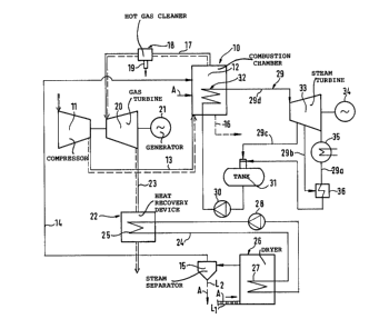
As is shown in Fig. 1, the fuel is burned in a pressurized
combustion or gasification unit or combustion device, which
comprises a combustion chamber 12 pressurized by means of a
compressor 11. The compressor 11 produces the necessary
combustion air, which is passed into the combustion device 10
through a system of compressed-air pipes 13. The compressor
ll raises the air pressure, e.g., to 12 bars. The pressure
may be typically within the range of 5 to 50 bars. At this
pressure, the air is then passed into the combustion device
10 .
Fuel A is fed into the combustion device 10. Owing to the
burning of the fuel, the mixture of air and of the flue gases
produced during combustion of the fuel is heated to about 850
to 1200C. Into the combustion device 10, through the steam
pipe 14, at least part of the steam is introduced that was
separated in the steam separator 15 from the fuel flow. The
steam and the fuel may also be passed as a mixture along the
duct 14, in which case no fuel separator 15 is needed.
One objective of the supply of steam is regulation of the
ultimate temperature in the combustion chamber. In such a
case, the steam is substituted for some of the excess air
that is normally needed. Owing to the supply of steam, the
compressor power is lowered and the net output of the process
is increased. Advantageously, a hot cleaner 18 for gases is
placed in the duct 17. Part of the ashes from the fuel are
removed from the combustion device 10 along the duct 16
straight out of the system, whereas the rest of the ashes
pass along with the flue gas flow into the flue gas pipe
system 17 and further to the hot cleaner 18 for flue gases,
where more contaminated gas and the ashes are removed out of
the process through the outlet duct 19.
After the cleaner 18 for flue or combustion gases the gases
are passed further along the gas pipe system 17 to the gas
turbine 20, where the gases expand and generate kinetic
1 334050
energy. By means of the kinetic energy, the compressor 11
placed on the same shaft as well 5 as the generator 21 are
rotated, said generator 21 producing electricity. The
pressure of the flue gases is lowered to the level of the
environment while, at the same time, performing the work
mentioned above in the gas turbine 20. The output obtained
from the gas turbine 20 is higher than the power required by
the compressor 11, whereby the excess power is recovered from
the generator 21 of the gas turbine.
After the gas turbine 20, the flue gases are passed into a
separate device 22 for the recovery of waste heat, for
example into a waste-heat boiler, along the duct 23. The
temperature of the flue gases after the gas turbine 20 is
typically 400 to 600C. These 15 gases are cooled to about
120C in the device 22 for the recovery of heat, e.g., a
waste-heat boiler. The heat obtained from the flue gases by
means of the device 22 for the recovery of heat is
transferred to drying of the fuel A in the dryer. After the
heat-recovery device 22 the flue gases are removed out of the
plant. In the heat-recovery device 22 it is possible to
generate steam, superheat stem, or to preheat the circulation
water, which is then passed further to the heat-exchanger of
the dryer, where the heat is transferred into the material to
be dried.
The circulation pipe system 24 for the heat transfer medium,
advantageously water and/or steam, includes, in the heat-
recovery device 22, advantageously a waste-heat boiler, a
heat exchanger 25 and, in a corresponding way, in the dryer
26, another heat exchanger, advantageously a condenser 27. A
pump 28 circulates the heat transfer 30 medium,
advantageously water, in the circulation pipe system 24.
In the heat-recovery device 22, heat is transferred from the
flue gases through the heat exchanger 25 into the water in
the circulation pipe system 24, whereby the water is
1 334050
vaporized, and said steam is 35 carried by means of the pump
24 into the heat exchanger 27 present in the dryer 26, where
the heat is transferred further into the material to be
dried.
In the steam-turbine process the supply-water pipe system 29
also includes a supply-water pump 30. The pump 30 is fitted
to pump supply water of the steam turbine 33 in the supply-
water pipe system 29 from the supply-water tank 31 to the
steam generator 32 placed in the combustion device 10.
The steam-turbine process includes a steam generator 32, a
steam turbine 33, a generator 34 that produces electricity
and is connected to the steam turbine 33, and a condenser 35
and a pre-heater of 10 supply water.
In the embodiment of the invention shown in the figure, the
combustion chamber 12 of the gas turbine 20, at the same
time, also acts as the boiler of the steam-turbine process,
wherein the steam passed to the steam turbine 33 is
generated. Thus, by means of the fuel A burned in the
combustion chamber 12 of the gas turbine 20, it is possible
both to heat the gases that pass to the gas turbine 20 and to
generate steam for the steam-turbine process in the steam
generator 32.
The temperature of the steam arriving in the steam turbine 33
is typically 530C and the pressure 100 to 180 bars. The
pressure prevailing in the condenser 35 is typically 0.05
bar, and the temperature therein 30C. In the condenser 35,
the steam is condensed to water. By means of the supply-
water pump 30, the pressure of the condensed water is again
raised to the level of the boiler pressure. The supply water
is pumped by means of the pump 30 from the tank 31 to the
steam generator 32, which is placed in the combustion chamber
12 of the gas turbine 20, as described above.
1 334050
From the steam turbine 33 a connecting duct 29a passes
through the condenser 35 and the pre-heater 36 to the tank
31. From the steam turbine 33 a connecting duct 29b passes
to the pre-heater 36 for the 30 purpose of pre-heating of the
supply water of the line 29a, taking place by means of bled
steam. From the steam turbine 33 a connecting duct 29c
passes to the tank 31. From the tank 31 a connecting duct
29d passes through the pump 30 and the vaporizer 32 to the
steam turbine 33.
The drying of the water-containing fuel A takes place in the
pressurized dryer 26 at the combustion pressure. The wet
fuel A that contains water is fed into the dryer 26 typically
to a pressure of about 12 bars. In the dryer 26, the wet
fuel A becomes dry and, at the same time, steam at the
combustion pressure is generated. Said steam is used as
injection steam for the gas turbine 20 by passing the steam
into the combustion device, i.e. the combustion unit lo.
The dry fuel A is passed out of the dryer 26 into the
combustion device 10 along a transportation path L1 of its
own.
In the following, the process of drying of the fuel A will be
described in more detail.
The fuel flow A is passed along the duct Ll or some other,
corresponding supply path into the dryer 26. As the fuel A,
it is possible to use, e.g.. milled peat having a moisture
content of 70%. In the process in accordance with the
invention, it is also possible to use fuel, in particular
peat, which has been dried only mechanically and whose
moisture content may be even higher than 75 %. The drying
takes place in the pressurized dryer 26 at the combustion
pressure, advantageously at a pressure of about 12 bars. In
the present application, a pressurized dryer is to be
understood as a dryer whose drying space is at a positive
pressure relative the atmospheric pressure. In such a case,
1 334050
the moisture contained in the fuel A is obtained as a medium
in the process. The steam produced in the drying process is
passed along the duct 14 into the combustion device 10 of the
gas turbine 20 into its combustion chamber 12. In principle,
the fuel A may be any solid 25 or liquid fuel that contains
water.
In the pressurized dryer the moist fuel is dried, e.g., to a
moisture content of 20 %. The drying energy for the dryer 26
is obtained along the pipe system 24 from the recovery 22 of
the heat from the flue gases of the gas turbine 20.
In the combustion device 10, the fuel A may be either burned
directly, or direct burning may be replaced by gasification
or partial gasification of the fuel and by burning of the gas
produced.
Purification of the gas may take place at the combustion or
gasification temperature or at some lower temperature. The
steam produced in the dryer 26 is passed along the duct 14 as
injection steam into the combustion or gasification device or
into some part of the pressurized gas line, either before or
after the combustion or gasification device 10. It is not
necessary to separate the steam and the peat in a steam
separator device 15, but the fuel and the steam produced can
also be passed as a mixture into the combustion or
gasification device 10.
Within the scope of the invention, such an embodiment is
possible in which a water-containing material in general is
dried in the dryer. The fuel of the power plant process may
be some material other than 10 that treated in the dryer.
Fig. 2 illustrates an embodiment of the invention wherein the
supply water for the steam-turbine process is pre-heated by
means of the energy obtained from the flue gases of the gas
turbine in the heat-recovery device 22. In this embodiment
-- 1~ --
-
1 334050
shown in the figure, in the heat-recovery device, the heat
from the flue gases can be transferred both to the drying of
the fuel A in the dryer 26 and to the steam-turbine process
for preheating of the supply water for the steam turbine 33
or for vaporization of the supply water for the steam-turbine
process or for superheating of said steam. In other
respects, the embodiment shown in Fig. 2 is fully equivalent
to the embodiment of Fig. 1. In the heat-recovery device 22
is located a heat exchanger 37, which is connected with the
supply-water pipe system 29.
From the steam turbine 33 a connecting duct 29a passes
through the condenser 35 and the pre-heater 36 to the tank
31. From the steam turbine 33 a connecting duct 29b passes
to the pre-heater 36 for pre-heating the supply water of the
line 29a, taking place by 30 means of bled steam. From the
steam turbine 33 a connecting duct 29c passes to the tank 31.
From the tank 31 a connecting duct 29d passes through the
pulp 30, the heat exchanger 37 and the vaporizer 32 to the
steam turbine 33.
Fig. 2 shows an embodiment of the invention wherein the steam
produced in the drying is circulated in the circulation
circuit 14b by means of the pump 14c and part of the steam is
taken along the duct 14 to constitute injection steam.
The dryer may also operate on some other principle, such as,
for example, so that the steam produced in the dryer is
super- heated and recirculated as superheated steam into the
dryer and, under these circumstances, no internal heat-
transfer pipe system in the dryer is needed.
Fig. 3 shows a third advantageous embodiment of the invention
as a schematic illustration. In this embodiment, the heat is
recovered from the waste heat of the gas turbine in the heat-
recovery device 22, and the heat is transferred to pre-heat
the supply water.
-- 11 --
3 0 5 0
In this embodiment, the supply water of the steam turbine is
circulated through the heat-recovery device 22 located in the
flue-gas duct of the gas turbine, the supply water is
circulated into the steam generator 32 located in the
combustion device 10 and, further, the superheated steam is
transferred to the steam turbine 33. This embodiment of the
invention differs from the embodiments described above in
that heat obtained from bled steams of the steam turbine is
used for the drying of fuel in the dryer.
Within the scope of the invention, a solution is possible
that differs from the embodiment shown in Fig. 2 in only in
the respect that the supply water of the steam-turbine
process is circulated through the waste-heat boiler 22 only.
In the embodiments shown in Fig. 3, the supply water passes
from the condenser 35 along the system of ducts 38 through
the heat exchanger 39 to the heat exchanger 40 placed in the
device 22 for the recovery of the heat from the flue gases of
the gas turbine 20, from which said heat exchanger 40 the
supply water is carried further along the connecting duct 41
through the branching point 42 along the duct 43 to the
supply-water tank 31. From the supply-water tank 31, the
supply water is pumped by means of the pump 44 along the duct
45 to the heat exchanger 46 placed in the heat-recovery
device 22. Along the duct 47, the pre-heated supply water is
pumped by means of the pump 44 into the pipe system of the
vaporizer 32 placed in the combustion device 10 and further
along the connecting duct 48 to the steam turbine 33. From
the steam turbine 33, a connecting duct 49 for bled steam
passes to the supply-water tank 31. The duct 50 is passed to
the pre-heater 39 for supply water, and in this way bled
steam from the steam turbine 33 is used for pre-heating of
the supply water passed along the duct 38.
Further, from the steam turbine 33 a duct 51 for bled steam
passes to the pressurized dryer 26. The duct 51 passes
- 12 -
1 334050
through the heat exchanger 52 placed in the dryer 26, and
further the condensed water coming from the dryer is passed
along the duct 53 through the branching point 42 to the duct
43 and further to the supply-water tank 31. The branching
may also be made to some other part of the supply-water line.
Thus, in the embodiments shown in Fig. 3, the fuel A is dried
by means of heat obtained from bled steams of the steam
turbine. The supply water that is carried to the steam
generator 32 is pre-heated by means of thermal energy
obtained from the flue gases of the gas turbine 20. Ia
manner corresponding to the embodiments shown in Figs. 1 and
2, the fuel is passed through the steam separator 15, from
which at least part of the steam is passed along the duct 14
as injection steam into the combustion device 10, and further
the dried fuel A is carried along the path L2 as fuel to the
combustion or gasification device 10 of the gas turbine and
the steam turbine.
In the embodiment of Fig. 3, the steam produced in the dryer
10 is recirculated in the same way as in the embodiment of
Fig. 2.
Within the scope of the invention, an embodiment is also
possible wherein the steam produced in the drying in the
pressurized dryer is recirculated through some waste-heat
boiler, e.g. through the waste-heat boiler 22 of the gas
turbine, and in which said boiler the steam is superheated,
whereinafter said steam is passed back into the dryer. Part
of the recirculation steam is taken as injection steam to the
gas turbine 20.
35 Within the scope of the present invention, the dryer used
is not bound to any particular dryer type.
- 13 -