Note: Descriptions are shown in the official language in which they were submitted.
1 334448
DESCRIP~ION
SPRING ~NI~S FOR MAT~RESS3S AND T B EIKE
The present in~e~tion relates to spring unitq ior
use in mattre~e_, spring upholstered iurniture and the
like, and to apparatus ior manulacturing said spring
units. The present in~ention also relates to a spring -
interior comprised of a plurality of said _pring units.~he present ~nvention iurther relates to an article oi
spring upholstered .urniture compriqed of one or more oi
sald ~pring interiors.
One well known t~pe Or spring interior i~ comprised
oi a plura}ity oi discrete coil spring3, each oi which is
~ewn into a respecti~e one of a plurality oi elongate
poekets formed in a length of calico or similar purpose
- material. ~he axes oi the springs lie generally parallel
with one anothe. 8UC~ that a band of 6prings is iormed,
with the upper and lower coils oi the springs defining
the upper and lower faces oi the band. A epring interior
can be fabricated .rom the band o~ springs in either one
Or two ways. Firstly, a plurality oi bands oi ~pringq
may be disposed side by side and adJacent rows clipped,
stitched, glued or otherwise ~oined together to form a
spring interior oi the de~ired size. Alternativelg, a
single band of spring ma~ be iolded back and iorth on
itseli to ~orm a zigzag pattern oi rows, whereupon
~acent rows are, agaln, ~oined together.
.~
1 334448
~ his type o~ s~ri~g interior is commonly reierred to
as a poc~eted sprlng interior owing to the iact that each
spring i9 contained within a respectiYe poc~et oi calico
- material. It i9 gener~ ac~nowledged that poc~eted
~pring inter~ors have a unique and particular luxurlous
ieel to them, and mattresse~ comprised of pocketed ~pr~ng
interior~ are said t~ have a ieeling o~ Roftne ~ about
them, wit~out lacking spring resilience. However one
describes the feel ~i a ~ocksted spring interior it
certalnly the case that theg commana a high price. Thi~
can be attri~uted t~ the considerable a~ount o~ time and
labour which i3 ~n~olvea in their manufac~ure, t~gether
with the ~act that the methoa of iabrication and as~embly
o~ pocketed Rprin2 interiorR does not readi~y lend itself
to automation; eæch spring is individuall~ stitched into
-its own poc~st ana bands o~ springs are then arranged in
rows to be joined together.
As we~l a~ being ~omparative~y expensive poc~eted
~pring interiors haYe certa$n inherent d~adYantages
a~sociated ~ith them. To accommodate the load on each
spring the springs may need to be made o~ relat~Yel~
heaYy gauge spring wire. In addition, becau~e the
8pr~ng~ are completed unsupported, except bg the pocket
o~ material in which each i8 contained, they suifer ~rom
2~ instability and ~ tendency to become dislocated. ~hi~
problem can be ~nimised-by ~eeping the spring~ ~ery
clo3e to~ethar, but thi~ leaas to one ~pring interiering
1 334448
with its immediate neighbours, and because a higher
spring count i8 nece~sar~ iurther adas to the high cost
Or pocketed spring lnteriors.
Another well known tgpe of ~prlng lnterior com-~ri~es
a plurality o~ bands Or continuou~ coil sprlng~ disposed
~ide bg side ana i~terconnected ~y a plurality of helical
wires, bands, ri~gs or the li~e. Each band of continuous
coil springs comprises a single length o~ wire ~n which a
plurality o~ in~iYidual coil Qprings ~9 formed. ~ach
spring is wound in the opposite direction to the springs
lmmediatelg adjacent to it in the band and is ~oined
thereto by wire link~ whlch are formed bg straight
extensions of the upper and lower c~il of each spr~ng.
~ach coil sprin~ is coupled with the next by having an
intermediate c~il t~erec~ interlaced with the
corresponding c~il of the ad~acent ~pring. When bands o~
continuous coil springs are assembled together t~ ~orm a
spring interior the~ are di~posed side b~ qide wlth the
longituainal axes o~ the ~pring~ generally parallel with
one another and the upper and lower coils of each ~pring
in an upper and lower plane, respectively.
Although th~s t~pe of spring interior does not
suf~er from "cuppi~g" to the same extent as a poc~eted
spring interio. and proviae~ good overall ~upport, it
lacks the ~lexibilitg and soft, ~et resilient feel of a
poc~eted sprir.g interior. Thls can be attribu~ed to ths
interconnec~ed me~h o~ spring~ which comprise the spring
1 334448
interior. A~ will be readily appreciated the continuou~
coil springs are not only ~oined together along each row,
but are al80 lnterlinked between ad~acent row~. ~hi~
reauces the abilitg oi each spring to act independently
when supporting a load and, lnstead, there ls a te-naencg
ior the ~prlng~ to be ~ulled toward~ the point oi
heaviest loadin~.
It is a~ ob~ect o~ the present inYention to proYide
a noYel spring unit.
It is another obJect o~ t~e present inYentlon to
provide apparatu~ for manu~scturing these spring units.
It is yet another o~ect o~ the present invention to
provide a spring i~terior comprising one or more o~ these
Rpring uni~s which obviate~ or substantially mltigates
the problems a~d disadvantage~ assoc~ated with the
conventional sprin~ interiors referred to hereinabove,
whilst retaini~g their adYantages.
It is still another ob~ect of the present invention
to provide an artic~e o~ sprlng upholstered ~urniture
comprised of one or more o~ the~e spring ~nterior~.
According to a fir~t aspect o~ the present in~ention
there is provided a spring unit compri~ing a continuou~
coil ~pr~ng contai~ed within a sleeve oi ~trong, yet
ilexible material.
~he sleeve of material may be compri~ed o~ virtually -
any strong yet ilexible material, though ~or preference
it i~ compriqed of calico. The sleeve of material may be
1 334448
lQosely fittlng or an exact ~it or it can be 80 tight a~
; to lightly compress the springs. ~o this end the sleeve
oi material ma~ be either i~-elastic or elastic as
required. lhe slee~e oi material ma~ be ~ormed
~eparate}g and the continuous coil ~pring threadea
through it, or t~e ~leeve may be formed bg wrapping one
, or more sheets oi material around the continuous coil
" springe.
Where the continuous coil ~pring i3 threaded through
the slee~e the slee~e i~ convenient~y carried on a
tubular former through w~ich the continuous coil spring
is drawn. As the continuous coil spring is drawn out
through the tubula- ~ormer it entrains the sleeve with lt
and draws the slee~e ofi the tubular former around it. }n
order to iacil~tatP en'ry of the continuous coil spring
into the slee~e or envelope the springs comprising the
continuou3 coil sp.ing may be compre~sed before entry
into the sleeve or en~elope.
Where the sleeve is formed by wrapping one or
more ~heet~ of ma~erial ~round the continuous coil
spring, both the s~eets o~ material and the
continuous coil springare conveniently fed together
through a iormer device wh~ch direct~ the edges oi the
sheets arou~d the continuous coil spring, therebg
enveloping the co~tinuous co~l spring in the sheet Or
material. ~he edges of the sheet or sheets are then
~oined together by stitching, glu~ng, heat welding or the
t 334448
liXe to complete the sleeve. Alternatively, the
continuous coil spring may be ~andwiched between two
sheet~ of matarlal the edges oi which are then ~oined
~og3ther to complete the sleeve of material around the
- 5 continuous coll spring.
~he term "conti~uou3 coil spring~ i3 under~tood to-
mean a plurality oi coil springs connected in series to
form a band or con~inuou~ length o~ coil springs. ~he
coil spring~ ~n each band are conveniently fabricated
~rom a ~ingle length oi sire and each spring i3 connected
to it3 ~mmediate neighbour by a wire link formed by an
exten~ion o~ the upper or lower coil thereof. ~o
facilitate fabricat~on each spring i3 wound in the
opposite direc~ion to ~t3 lm~ediate neighbour in the
bandJ though the springs can all be wound in the same
direc~ion ~3 SO re~uired. A~ an alternative to
~abricating each band of coil ~pr.ngs from a single
}ength of wire, eacn coil spring may be ~ormed separate~y
ana connected to it3 immediate neighbour in-the band by
ring~, bands, wire link~ or the li~e.
20 - Accor~ing to a Gecond aspect o~ the present
lnvention ther~ i3 provided a spring interior comprising
a plurality of lengths of #pring unit according ~o the
~irst aspect of the present in~ention, the leneths oi
~ spring unit being d~3posed side by side with the
longitudinal axe~ oi the spring3 generally parallel with
one another and ~he upper and lower coil~ of each spring
. . , ; . . ,
~ 334448
lying in an upper a~d lower plane re~pectivelg.
In a ~irst embodiment the said plurality of lengths
Or spring unit dispo~ea 8~ae b~ siae are ~ormea bg
repeatedly folding a ~ingle length o~ spring unit bac~
ana iorth on it~elf such that a generally zigzag shapea
configuration is de~ined. Alternativel~, a single length
of spring unit can be wound round on itseli in a splral
to ~orm the spring interior.
- In a secona e~bodiment the ~pring interior is
comprlsed oi a plurality of aiscrete length~ of ~pring
unit disposed side by side.
~ he said plura'ity of length~ oi spring unit
disposed side b~ ~ide may be ~-onnected or ~oined together
by a variety of means. In this respect, the coil ~pr~ngs
~rom adjacent len3'hs of spring unit may be linked
together and/~r th_ slee~es o~ material may be ~oined
together. ~he coil springs may be ~oined together by
means of, for exa~ple, hog rings and/or ~titche~ which
pas~ through the slee~e~ of material. ~he slee~e~ may be
~oined together by, for e~ample, welding, ~titching or
gluing. Other li~lng means and/or ~oining techniques
may al30 be employed as will be readily apparent to tho3e
~ illed in the ar~. Additionally, the said plurality of
lengths of spring u~it ma~ be contained within an outer
ca~ing or en~elope.
In ~et an~ther embodiment o~ the ~pr~ng interior a
pluralit~ of length~ of continuous coil sprlng, ~ormea
~ I 334448
either ~rom di~crete lengths o~ continuous coil spring,
or ~rom a s~ngle length oi continuous coll spring
repeatedly ~oldea bac~ and forth on itself are sandwiched
between two 6heet3 o~ material, the two sheets
being ~oined together between adjacent lengths oi
continuous coil spr~ng, thereby enclo~ing each length d~
continuous coil sprlng in a respecti~e slee~e o~
material. It will be appreciated that the two sheets o~
~t material may be ~oined together w~th the continuous coll
spring~ in situ therebetween, or, in the alternative, the
continuous coil spring~ may be introduced into the
slee~e~ in a separate operation.
A3 will be readily appreciated in the third
embodiment of the spring interior described immediately
above ad~acent lengths of sleeved continuou~ coil-spring
are joined together by the material between adiacent
slee~e. ~owever, ~his conection may still be
supplemented by a variety o~ connecting means, including
hog rings and/or 3~tc~ing lin~ing the coils o~ ad~acent
lengths o~ continuous co~l ~prin~, and stitching, gluing
and/or welding together o~ adjacent sleeves.
Preferably, the spring interior comprises an
additional length of spring unit in accordance with the
~ir~t aspect o~ the pre~ent invention which extends
around the perime'er o~ the said plurality oi spring
units disposed side b~ side, thereb~ de~ining a border
therearound.
. .
.
1 334448
- Preierably, the ~pring interior i~ secured to and
supportea b~ a peripheral irame. Thi3 peripheral ~rame
-- ma~ comprise a pair o~ steel bands or wires each o~ which
encircles the spring units compri~ing t~e ~pring interior
and lie~ in the same plane as a respective ~ain face of
the spring lnterior.
Owing to the uniq~e con3truction o~ the ~pring
interior of the present invention lt3 performance cannot
be directly compared wlth either conventional poc~eted
spring interiors or con~ent~onal continuous coil spring
interiors. ~evertheless, lt has been ~ound to have a
~eel approaching that of a conventional pocketed spring
interior, whilst retaining the bene~its o~ a conventional
continuous coil spri~ interior.
~S By enclosing each ~ength of continuous coil spring
in its own sleeve and isolating it from ad~acent length3
of continuous coil spring the coil~ in each length of
continuous coil spring are allowed to move independently
o~ tho~e in the adJacent ~engths o~ continuous coi~
spring. ~his at least mitigates the tendency of
conventional continuou~ coil spring interiors to pull the
spring matrix toward3 the point of heaviest load. It
also result3 in very ~uch les3 noi~e from the coils a~
they move relative t~ one another under load as compared
2S with conventional continuous coil sprin~ interiors.
~ he large number o~ ~pr1ngs per unit area which 19
made po~slble by the use of continuous co$1 springs
t 334448
allow~ light gau~e w~re to be used which iQ relativel~
ea3g to work. Additionally, the u~e oi continuou~ coil
springs, each enclosed within it~ own sleeve, ma~es
~embl~ oi the spring interior a relatively simple
matter which i~ readil~ suited to automation. Further,
the lin~ wire between ad~acent coils in each length oi
continuou~ coil spring provides an additional torsion
spring and helps to prevent "cupping" from occurring.
According to a third aspect o~ the pre~ent invention
there i3 provldea an article o~ upholstered ~urniture
compri3ing one or more sprln~ interior~ according to the
second aspect o~ the present inYention~
~hough by no me2ns an exhaustive list the term
"art$c.1e of uphol3tered furniture" may be taken to
include mattresses ~or beds, spring upholstered cu~hion~,
whether formea sepa.ately or as an integral part of the
article o~ uphol3te~ed furnlture, 3eat sguabs, bac~
rests, arm rest3, head re~ts, headboard3 for bed3 and the
like.
An embodiment o~ the present invention will now be
de~cribed, b~ wa~ o~ example, wlth re~erence to the
accompang$ng drawing~, in wh$ch:
Fig. l show~ a perspective view of a spring unit
according to the fir~ a~pect of the pre~ent invention;
Fig. 2 show3 a ~che~atic view of a ~ir3t apparatu~
for enveloping a ba~d of coil ~prings $n a cloth ~leeve;
Flg..3 show~ a schematic ~iew of a second apparatus
1 334448
~ for enveloping a band of coil springs in a cloth sleeve;
Fig. 4 8~0W~ a diagrammatic plan ~iew o~ a ~irst
spring interior embodylng the second aspect oi the
present in~ention;
~ig. 5 shows a aiagramat~c plan ~iew oi a second
spring lnterior emboaging the secona aspect oi the
present in~ention;
Pig. 6 shows a section through a spring interior
embodying the second aspe-ct of the present in~ention and
employing a plurallty o~ integrally iormea sleeve~;
. Fie. 7 ~how~ a schematic view oi an apparatu~ ~or
simultaneousl~ enveloping each oi a plurality oi lengths
oi continuous coil spring in a reæpecti~e sleeve and
producing a spring $nterior--as shown in Fig. 6; and
Pig. 8 shows P diagramatic ~iew oi a mattress
comprising a pair oi spring inter~or~ according to the
~econd aspect o~ t~e present i~ention in which the
exterior uphols~er~ has been partially cut away.
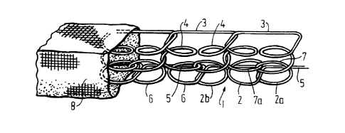
Re~erring to ~ig. 1 o~ the accompanying drawing~
there i9 shown a 3pring unit emboaying the present
invention comprisin~ a single band of continuous co~l
spring3 1 which i3 iormed from a length o~ spring wire
shapea to iorm a plural~ty oi indi~iual coil spring~ 2.
Each spring 2 i3 wouLnd ~n the opposite direction to it~
2S two immediate ~eighbour~ in the abnd and i8 ~oined to one
ad~acent ~pring 2a ~y a wire lin~ 3 which ~orm~ an
lntegr21 extension oi the upper coil~ 4 oi the two
1 ~34448
~ springs 2, 2a and to th~ other adjacent spring 2b bg a
wire link 5 which iorms an integral exten~lon oi the
lower coils 6 o~ the two springs 2, 2b. ~ach spr~ng 2 i~
coupled to the s~ring 2 ad~acent to it by having onc
intermediate coil 7 thereoi lnterlaced with the
corresponding intermediate coil 8 o~ the next spring.
~he continuou~ coil spring described hereinabov~ 19
- o~ con~entional construction, but it should be unaerstooa
that the spring unit according to the pre~ent ~nYen~ion
- 10 i~ not intended to be limited to this particular
con~iguration and can comprise continuou~ coil sprlngs o~
any con~iguration. For example, succes~ive coil spr~ngo
-in a band need not be wound in the oppos~te direction,
but can all be wound in the same direction ~ ~o
required. ~urther~ore, each coil spring can be iormea
separa~ely and cornected to $ts immediate neighbour in
the band by rings, band~, wire link3 or the like.
~ he band of continuous coil spring3 1 is enveloped
or sneathed within a sleeve oi calico material 8 whic~ i8
closed at bot~ ends to complete the spring unit accoraing
to tne present invention. ~he sleeve o~ material may be
~ loo~ely ~itting or an exact flt or it can be 80 tight as
to lightly compres~ the ~prings. To thi~ end the ~leev~
oi material may be e~ther in-elastic or ela~tic a~
required. One or ~ plurality oi spring uni~ embodying
~ the present invention can be assembled to ~orm a ~pring
interior a3 will be de~cribed later hereLnbelo~.
... .. . .. . . . . . . .. .. . .
t 334448
Two methoas o~ en~eloping the continuous coil
sprine 1 ~n the ~leeYe o~ calico material 8 w~ll now be
described:-
In a first such method, which is illu~trated with
S reference to ~i~. 2 o~ the acco~panging ara~ings, a~^
- separatelr iormed slee~e oi calico material 8 ~ carriea
on a tubular former 9 and the band of continuou~ c~i}
~prlng t i~ wound onto a reel 10. The free end oi the
band 1 is drawn oif the reel 10, through one end -Or the
tubular former 9 and out the other end. As the band 1
pa~se~ through the tubular for~er 9 it draws oif the
slee~e oi calico material from the tubular iormer 9 and
entrain~ it around itseli. Although not shown the iree
end of the en~elo~ed band o~ continuous coil spring may
be wound onto a second reel for use later. Once enough
oi the ~and 1 has been covered with the calico sleeve 8,
both are cut and the open end~ Or the calico slee~e 8
stitched together.
In an alterna'lve method, lllustrated with reierence
to Fig. ~ of the accompanging drawings, a continuous
sheet of calico material 11 ls carried on a reel 12 and
the band 1 i9 wound on a reel 10. The free enas oi the
calico material 11 and o~ the band 1 are drawn through a
V-shaped former 13 which serves to direct the sides oi
the sheet 11 up ar.d around the ~and 1. Abo~e the
V-~haped former 13 is a stitching machine 14 which
~imu~taneously dra-~s the s~de of the calico material 11
t 334448
together and stitches them together. Thus, the band 1 i9
coYered in ~ eleeve o~ calico material 8.
As with the method oi manuiacture described with
rersrence to Fig. 2, once the required len~th oi band 1
has been coverea with the calico sleeve 8, the band 1 may
be cut to length and the open ende oi the sleeve 8
stitched together.
Although the techniques illu trated with reierence to
Pigs. 2 and ~ both show the band 1 being drawn rrom a
reel 10, it will be appreciated that both techniques may
al~o be applied to 'he band 1 a~ it comes of~ the coil
~or~ing and coil in~er~acing equipment.
Re~erring now to Fig. 4 oi the sccompanying arawings
there is hown a diagramatic plan view o~ a spring
interlor embo~ding the ~econd aspect of the present
in~ention ln which a plural~ty of discrete lengths o~ the
spring unit 15 desc.ibed with re~erence to ~ig. 1 are
disposed s~de by ~ide. Adjacent len~ths 15 are connected
together by hog ri~g3 16, each o~ which serve~ to connect
a spring 2 from one length 15 to the neighbouring ~pr~ng
2 in the adjacent length 15. Around the perimeter of the
spring interior, 0~20site the upper and lower main ~aces
thereo~, there ls ~rovided Q peripheral ~rame 17 wh~ch
proYide3 support ~,, and rigidity to, the edge~ of the
~prlng interior. ~ach ~rame 17 is connected to the
spring interior by 3eans o~ short ~trips o~ metal 18 each
oi which is connected between the ~rame 17 and an
14
1 334448
ad~acent spring 2 of tho sprlng interior.
As will be readilg appreciatea ~rom Fig. 4 the
sprlng lnterior 1~, ~n the con~entional sen~e, neither a
continuous coil spring interior, nor a pocketed coil
epr~ng interior. EoweYer, it retains ieatires of both
types. ~pecificall~, the independent movement allowed .
between the coil ~pring~ 2 in ad~acent lengths 15 oi the
spring unit according to the ilr~t aspect of the pre~ent
invention aYoids the tendency o~ conventional continuou~
1~ coil sprlng in~er~o,rs to pull the s~ring matrix ~owards
the point oi heav~est loaa. This ensures much more
uni~orm and e~e~ support~ror the load and results in
greater com~or~ f~r a ~erRon resting on the spring
interior. ~oreoe~_r, because each length o~ continuous
coil ~pr~ng 1~ lsolatea ~rom its neighbour by the slee~e
of calico mater~al there is much less ~pring noise as the
spring~ 2 ln adjacent lengths moYe relati~e to one
another.
~he spring l~tarior of the present invention still
ma~e~ u~e o~ continuous~co~l,sprl~ng~,_ana as suc~
manufacture o~ the spring interior is verg much quicker,
simpler and le~3 costly than with conventional pocketed
coil ~prlng ~terior where each coll ~ust be ~eparately
secured lnto it3 own pocket ln the ~prin~ interior.
Additionally, the large number Or coll spr~ng~ per unit
area ln a cont~nuous coil sprlng interior mean3 that the
gauge o~ apring wire used can be reducea witho~t
-- . t 334448
s~gnificantly af~ectlng the per~ormance o~ the spring
interior.
~ Reierring now to ~ig. 5 there is ~hown a diagramatic
plan view oi an alternatiYe ~pring interior. embodg~ng the
~ 5 second aspect o~ the present in~ention. In th1s., embodiment a single length 19 of the qpring unit
de~cribed with reference to Fig. 1 ~ folded back ana
~orth on itself several times to ~orm a plurality Or rows
disposed siae bg side. As in the pre~ious embodiment o~
Pig. 4 ad~acent roYs are connected together by mean~ oi
hog clips 18. A further length l9a oi the spring unit
~e~cribed with reference to ~og. t i8 wrapped around the
perimeter o~ the spring interior to finish the edge ~
A~ in the spring interior described with reference to
Fig. 4 a peripherzl frame 17 i3 provi~ed opposite the top
and bottom main fzces of the spring interior to provide
support for and r~gidit~ to the edges of the spring
interior.
Re~erring now to Fig. 6 of the accompanying drawings
there is ~hown get a~other spring interior embod~ing the
second aspect of the pre~e~t inYention in which two
iacing sheets 20 Pnd 2t of calico material are stitched
together at ~pace~ intervals 22 along their wldth. ~he
stitching ex'end3 the ~ull length of the sheet3 20 ana
: 25 21, and a3 such de~ine~ a plurality oi elongate sleeves-
: 23. Within each slee~e 23 there io contained a d~screte
length o~ continuous coil s~rin~ 24. To complete the
t 334448
spring interior the open enas of the slee~e 2~ are
~ stitchea to~ether.
It will be unaerstood that the two sheet3 o~
material may be 3titched together with the continuou~
coil ~prings 24 in-3itu therebetween using, for example,
8 mult~-neeale quilting machine or multi-head ~ewing
~ch~e, as 8~0wn in Pig. 7. With reference to Fig. 7
there i~ shown a p1urality o~ reels 25, each o~ which
carries a band of continuous coil spring 26. Above and
below the reels 25 there is proYided a roll 26, 27 of
calico material 28, the width of each o~ which ls
81~ghtl~ greater than that oi the spring interior to be
produced. Positioned in iront of the reels 25 and the
rolls 26 iq a mult~-head sewing machine 29 compri3ing a
lS plurality o~ ~ewing heads 30. -
In uqe, the bands o~ continuous coil spring 26 aredra~n ~rom the reel~ 25 ana are sandwiched bet~een the -
calico ~aterial 28 ~rawn from the upper and lower rolls
26, 27. ~his sa~dwich o~ materlal 28 and band3 26 is
then drawn through the multi-head sewing machine 29 whlch
i3 80 configured tha~ a sewing head 30 passes along each
siae of the bands 26 and st~tches together the upper and
lower 6heets of cal'co material 28. ~hus, each band 25
is enclosed within ~ respecti~e sheath 31 of cal~co
material 28. Aiter production the resultant spring
~nterior can be cut to slze and the open ends of the
~-sheath~ 31 ~titched together.
- 1 334448
A~ an alternatlYe to the aboYe method of
manuiacture, the two sheets 20 and 21 mag be stitchea
togsther separate~y a~d the continuou~ coil spring.q 24
introducea into the sleeve~ 23 ln a separate operation
u~ing, ior e~ample, a plurality o~ tubular ~ormer~ to
s~pport each sleeve whilst a leneth o~ continuous coil
sprin~ 24 i~ introduced therein aQ de~cribed hereinabove
with re~erence to Fig. 2.
Re~erring now to Pig. 7 of the accompanying drawing~
there i~ shown a mattres~ 32 comprislng two spring
interiors 33, 34 embod~ing the present invention which
are separated from each other by a layer o~ wool padding
material 35 and coYered with a suitable covering materia
36.
.
........................................................
18