Note: Descriptions are shown in the official language in which they were submitted.
1 334636
The invention relates to an apparatus, in particular a machine, for
pressing and dewatering or filtering of sludges, fibrous material
suspensions or cellulosic material suspensions, having two circulating
filter or screen belts between which the material to be pressed and
dewatered or filtered is made to pass and two circulating pressure
or supporting belts for supporting the two filter belts on their sides
facing away from the material to be treated, as well as supporting
and pressing means, in particular stationary during the operation of
the apparatus for the pressure or supporting belts on their sides facing
away from the filter belts and the material to be treated. The material
to be pressed or treated is preferably introduced into the apparatus
as a pretreated or dewatered material, such as in the form of a web,
which may consist of uniformly charged crushed filter cake.
It is the object of the invention to provide an apparatus or machine
of the type previously mentioned which exerts a continuous pressure
over an extended period of time on the material to be treated and
whose compression zone is formed in such a manner that the differences
in the thicknesses of press materials and filter cakes as well as
the compression of material and filter cakes can be well accommodated
without loss of compression force.
This object is achieved according to the invention - starting out
from the apparatus or machine initially described - in particular
by providing for the supporting or pressing means to form a tunnel
or the like, in particular a pressure space or cavity having a straight
longitudinal axis, in the compression, dewatering or filtering zones,
the pressure or supporting belts being sealed against the walls of
- 2 -
1 334636
the tunnel directly or indirectly, locally defined, in particular in
several locations of the tunnel, by elastic belts or the like at least
essentially enclosing the pressure and supporting belts and the filter
belts and the material to be treated on all sides. This creates many
possibilities of influencing the material to be treated within the
apparatus or the machine, in particular because the pressures and
thus the pressing of the material can be appropriately controlled in
the sealed treatment tunnel. These effects can be particularly well
influenced if the sealing belts are formed as closed or open hollow
bodies, preferably as elastic hollow pads or bladders, in particular
tube-like. A practical embodiment of the invention is characterized
in that the cavities of the seals arë connected to a pressure source,
in particular a pump.
A preferred embodiment of the apparatus or machine according to the
invention is characterized in that the elastic sealing belts, in
particular the hollow bodies or hollow pads, are attached to the tunnel
wall by means of inserts.
A convenient control of the pressing or filtering operation can
be achieved according to the invention by providing at least three
sealing belts between which compression zones, in particular of different
pressures,are formed. If several compression zones are provided, it
is convenient for the pressure to increase from compression zone to
compression zone in the running direction of the belts and then to
decrease towards the material outlet.
In practice, it may be particularly convenient to provide the
pressure belts on the side of the screen belts with longitudinal grooves
for discharging the pressed-out filtrate, in particular counter to
1 334636
the running direction of the belts, and to provide tubes or the like
stationary and gliding during the operation of the apparatus in the
longitudinal grooves for the discharge of the filtrate, the tubes or
hoses conveniently extending from the entrance side of the pressure
belts into the first compression zone. The filtrate discharge can
conveniently be enhanced by providing for the belts to pass from inlet
to outlet in a, particularly slightly, ascending path.
The control of the sealing problem and thus of the pressure
conditions in the treatment tunnel created according to the invention
is enhanced according to a further development of the invention by
providing for the pressure belts to be thicker in their marginal zones
than in their centers and/or for the outer edges of the pressure belts
to be rounded, in particular in such a manner that the entire package
of belts consisting of pressure belts, filter belts and material
being treated, has a cross section of approximately rectangular shape
with an approximately semicircular lateral boundary.
Sealing problems, pressure conditions and dewatering success may
also be favorably influenced by providing for the pressure belts formed
in particular thicker in their marginal zones than in their central
zones to be in contact with one another in the marginal zones and to
be provided there with at least one longitudinal groove in which a
co-advancing sealing cable or rope is provided and for the tunnel or
the like of in particular approximately rectangular cross section
to be subject to pressure medium, in particular pressure fluid,
conveniently at least between the first and the last sealing belt
enclosing the belt package viewed in belt advancing direction.
The structural layout of an apparatus or machine according to the
1 334636
invention is conveniently such that the tunnel or the like in
particular formed with rectangular cross section is formed by pressure
plates and tong-like parts tightly gripping them laterally. It may
be of advantage for the protection of the seals, but also for increasing
the sliding capacity of the pressure belts, to provide wear protection
sleeves between the belt package and the sealing belts, in particular
the sealing hollow bodies, for instance sealing tubes,a gap conveniently
being adjustable during the operation of the apparatus between sealing
belts and pressure belts by means of leakage medium, in particular
leakage fluid, for instance leakage water, but under certain
circumstances also oil or alcohol.
In setting up the system according to the invention, the sealing
belts may be formed divived, preferably at least once, the belt ends
on the dividing joint(s) being mutually sealingly connected by clamping
by means of inserts inserted into the tunnel or by means of adhesive.
The wear protection sleeves are also formed divided, preferably in
two parts, the conveniently overlapping part ends being suitable for
mutual connection, in particular by means of adhesive.
In practice, the control of the pressure conditions is particularly
facilitated by providing for the sealing belts formed as hollow
bodies, hollow pads or bladders to be subject to various internal
pressures exerted by a pressure medium. A particular influence on the
pressure conditions can further be achieved by the individual, hollow
sealing belts being composed of several hollow belt portions of which
the cavities on the belt edge are subject to a medium of higher
pressure during the operation of the apparatus than the remaining
belt portions. To this end, the in particular hollow sealing belts
-- 5 --
1 334636
in an approximately rectangular belt package or tunnel of
approximately rectangular cross section can be composed of
four, in particular hollow, portions, namely of one each
portion extending above and underneath the belt package and
one each portion extending over the lateral height or the
thickness of the belt package, said four individual portions
being mutually sealingly connected in the area of the
package edges which are there conveniently faced at an angle
of 45 degrees.
Even if favorable pressure conditions are
maintained, the consumption of operating energy can be kept
particularly low if only the zone with the highest pressure
in the tunnel is connected to a pressure source, in
particular a pump, which introduces in particular pressure
medium, conveniently pressure water, into said zone, and if
the adjacent zones of the tunnel are subjected to pressure
by means of the leakage water or the like flowing between
the sealing belts and the belt packages.
A convenient circulation of the pressure medium
can be achieved by providing for the leakage or compressed
water to be drained or drawn off after flowing through the
tunnel compression zones upstream of the sealing belts or
sealing boxes in the inlet and outlet ends of the belts or
of the tunnel, in particular to be connected to a working
container taking up the pressure medium and connected to the
pressure source, in particular the pump. The end sealing
belts or sealing boxes are conveniently formed
leakage-water-tight, in particular as hollow bodies with
about 0.2 to 1 bar of superpressure in opèration, preferably
with air as the pressure medium.
-
1 334636
Therefore, in accordance with the present
invention, there is provided an apparatus for the treatment
of sludges, fibrous material suspensions or cellulosic
material suspensions by pressing and dewatering or
filtering, comprising:
two circulating filter belts, each belt having a
side thereof facing the other belt, between which the
material to be treated is made to pass;
two circulating pressure belts for supporting the
sides of the filter belts which face away from the material
to be treated, the pressure belts and filter belts forming a
belt package wherein the filter belts are disposed between
the pressure belts with the material to be treated passing
between the filter belts;
means for circulating said pressure belts and
filter belts in a moving direction,
means for supporting the belt package, which
includes enclosing walls forming a tunnel through which the
belt package is disposed, said tunnel having an inlet end
and an outlet end, and said belt package moving through the
tunnel in said moving direction from the inlet end to the
outlet end;
a plurality of sealing members attached to the
walls of the tunnel and extending completely around the belt
package transverse to said moving direction of the belt
package, said members providing a seal between the tunnel
walls and the belt package;
a source of fluid under pressure; and
means for introducing fluid from said source into
the tunnel between adjacent sealing members to form
compression zones along the belt package whereby fluid
- 6a -
1 334636
pressure may be applied to said belt package to compress the
material to be treated.
The invention is explained in the following on the
basis of exemplary embodiments with reference to the
accompanying drawing, wherein
Fig. 1, Fig. la and Fig. lb are schematic
representations of
1 334636
dewatering apparatus or machines provided with the pressing or
compression means according to the invention;
Fig. 2 shows a cross section in enlarged scale through the core
part of the machine or the apparatus along line II-II in Fig. 1;
Fig. 2a to 2e show variants in similar sections, although only
partially represented;
Fig. 3, 3a and 3b represent schematic longitudinal sections along
line III-III in Fig. 2;
Fig. 4 and 5 show similar sectional views through the seals and
immediate1y adjacent apparatus and machine parts.
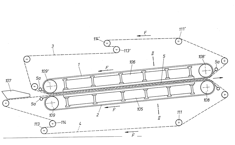
The dewatering machine of compact construction schematically
represented in Fig. 1 comprises a lower endless filter belt 4 and an
upper endless filter belt 3 between which the material to be dewatered
is made to pass. The lower filter belt 4 is formed as a supporting
screen and passed over a number of rolls, namely a screen belt
adjust;ng roll 111, a deflection roll 114 and a tension roll 113. The
upper filter belt is formed as a cover screen and made to pass over
guide rolls 114', a tension roll 113' and an adjusting roll 111'.
The material to be dewatered is charged from a charging device
107 onto the lower filter belt 4 so thatacake5 of approximately uniform
thickness is formed to be dewatered between the two filter belts 3,4.
In the compression zone, the two filter belts 3, 4 are supported
by circulating5 endless pressure belts 1 and 2. The lower pressure
belt 2 and the upper pressure belt 1 are trained over deflection rolls
109, 109' and optionally over tension rolls and adjusting rolls. The
drive may act on rolls 108, 108'. Smaller deflection rolls may be
provided at the start and end of the pressing line. The pressure belts
1 334636
192 are made of elastic material impermeable to water and liquids,
such as rubber or plastics materials. The supports 1~5, 106 serve for
subjecting the pressure belts 1,2, the filter belts 3, 4 and thus the
press cake l~dse(3 therebetween to the required compression force. These
supports 105, 106 take up the entire com~ression force and to this end
are of very sturdy construction. On both sides of the dewatering
machine, the upper and lower supports 105, 106 are connected to one
another so as to obtain a short transmission path of the entire forces.
This has the advantage that the very high compression forces do not
have to be transmitted to the machine bed (foundation) so that this
machine bed can be of comparatively light and inexpensive construction.
According to the invention, the transmission of forces from the supports
105, 106 to the mobile pressure belts 1,2 is effected by a special
hydrostatic pressure means represented in detail mainly in Fig. 2 to
5.
~ hile the compression zone in ~ig 1 is linear, Fig. 1a schematically
shows a curved compression zone. The pressure belts in this case bear
the reference numbers 1', 2', while the filter or screen belts are
designated 3', 4'. The supports for the pressure belts are the drum
105', on the one hand, and the curved body 106', on the other hand.
The linear compression zone could be replaced by those of convex or
concave curvature if necessary.
Fig. 1b shows a similar variant. Filter or screen belts 3,',4' are
subject to the action of pressure means 1', 2', the pressure means
1' being formed as a belt, the pressure means 2' being formed as a
circulating, optionally driven torus or supporting ring resting or
centered e.g. on supporting rolls 120. The material is charged at 121.
1 334636
A discharge means for the pressed material is designated 122. A pump
123 or another pressure source supplies the required pressure conditions
outside of the pressure means (torus 2', belt 1'). Supports 105', 106'
act on the pressure means 1', 2' and the filter belts or screen belts
3',4' via hydrostatic pressure devices to be described in the
following.
The pressure belts 1,2 are conveniently provided on the screen side
with longitudinal grooves (Fig. 2) 1a, 2a through which the filtrate
is discharged counter to the direction of belt advance (see arrow F!)
(Fig. 1).
The filtrate is conveniently sucked off according to Fig. 2 by
stationary tubes or hoses 5a (also refer to Fig. 1!) sliding in the
longitudinal grooves 1a, 2a, one each tube or hose preferably being
associated with each groove. As evident from Fig. 1, these tubes
conveniently reach from the inlet side of the belts 1,2 to the first
compression zone to prevent filtrate sucked back from wetting the still
unpressed cake. Sucking back of the filtrate is conveniently enhanced
by a belt path slightly ascending in running direction (see Fig. 1!)
Fig. 2 shows a section along line II-II in Fig. 1, thus perpendicular
to the advance direction of the apparatus or machine. The pressure
belts 1,2 are thicker in their marginal zones and formed for instance
rounded on their edges, so that the entire belt package composed of
pressure belts 1,2, filter belts 3,4 and the treated material or cake
S is of approximately rectangular cross section with laterally attached
semicircles. It is also possible, however, to provide chamfers instead
of the roundings or a polygon as the edge boundary or a belt package
with rectangular cross section.
1 334636
~~ The pressure belts 1,2 are provided near their edges with grooves
5a in which sealing cables 6 preventing the penetration of compressed
water between the pressure belts and at the same time mutually centering
the two belts are co-advancing. This constitutes guiding and sealing
grooves in circulating direction .
The belt package passes a rectangular channel charged or filled
with a pressure medium, preferably a pressure fluid, said channel being
sealingly enclosed on top and bottom by the pressure plates 7 and
on its sides by the tongs 12, so that a tunnel 21 is formed. This channel
or tunnel 21 is subdivided in advancing direction into several
compression zones Z1 to Z5 (Fig. 3!), for instance with pressures
increasing in advance direction.
According to the invention, special boundaries allowing movement
of the belt package at simultaneous tight sealing action are provided
at the inlet and outlet of the belt package into the tunnel 21 and
out of the tunnel 21 and at the separating sites between the individual
compression zones, Z1 to Z5. According to the invention, the seals
are elastic seals 8, in particular in the form of tubes or hoses,
enclosir,g the belt package.
The boundaries of the compression zones Z1 to Z5 are preferably
self-adjusting bladder seals 8 directly installed in the channel or
tunnel 21 by means of an insert 9. A small amount of leakage water
is allowed to flow between the belt package and an wear protection sleeve
lO to be preferably provided so that the belt package can be pulled
essentially without contact and thus with low fricti!on through the
seals consisting of bladder seal 8 and wear protection sleeve 10.
These bladder seals separate the compression zones Z1 to Z5
- 10 -
1 334636
enclosing the entire belt package from one another and also insulate
them against the environment. This is possible because this seal
is disposed around the belt package normally to the belt advance
direction and thus encloses the entire belt package.
The bladder seals 8 consist of resiliently elastic and dense material
having tensile strength, for instance rubber with a fabric insert.
The bladder seal 8 is fastened by means of an insert 9 to be described
later on.
Each bladder seal on principle encloses the belt package endlessly.
As previously described, a wear protection sleeve 10 is provided between
the bladder seal 8 and the belt package and protects the bladder seal
against wear.
The sleeve 10 also passes around or encloses the belt package
endlessly on principle, but for assembling reasons is preferably formed
in two portions, with top and bottom portion of the sleeve 10
overlapping in the marginal zone.
The bladder seal may also be divided into several portions instead
of only one. Each bladder seal thus consists of several portions, with
the ends of the individual bladders possibly clamped into the insert
9. So, for instance, it is possible for better adaptation of the amount
of leakage water to subject the individual bladders located in the zone
of the belt edge to higher pressures than the individual bladders
disposed on the plane belt surface.
At rectangular embodiment of the belt package, the division could
be effected into four portions 8', 8" according to Fig. 2e, with two
individual bladders (8') extending over the entire belt width and
two individual bladders (8") extending merely over the thickness of
- 11 -
1 334636
the belt package. The individual bladders 8', 8" preferably abut at
an angle of 45 degrees.
Fig. 3 shows a schematic longitudinal section in machine advance
direction representing the arrangement of the compression zones. Fig.
3 shows an exemplary arrangement of several boundaries in the form
of sealing inserts with pressure bladders so that five different
compression zones Z1 to Z5 are created. Further seals 30 and 31 serve
for separating the leakage water.
The zone Z1 with the highest pressure is supplied with pressure
fluid, preferably water, by a pump 32. The amount of water supplied
passes the adjacent sealing inserts or boundaries 8 in the adjacent
compression zones Z2, ZS of lower pressure as leakage water and passes
to the subsequent compression zones Z3, Z4.If the arrangement is composed
of seveal stages, the amount of leakage water need be used up only
once and the pressure can be reduced via any given number of sealing
inserts and thus compression zones. This means reduced pump output
for the generation of compression force and moreover permits high
compression forces, as the pressure bladder is only subject to the
respective differential pressure between the two compression zones
and the bladder material is thus not too highly stressed.
After the last compression zones in the direction of the leakage
water flow (upstream of the seals 30 and 31), drains 36, 37 through
which the compressed water is conveyed to a working container 38 and
thus returned to the circulating pump 32 are provided in the channel
or tunnel 21.
Sealing boxes 30, 31 provided outside of the drains 36 and 37
in the channel or tunnel 21 prevent the leaking of the nearly
- 12 -
1 334636
pressureless circulating water from the machine or apparatus. These
sealing boxes are of the same construction as the zone boundaries, but
subject to about 0.2 to 1 bar of superpressure and preferably fed with
air as a pressure medium~ so that the wear protection sleeves 10 of
these seals, for instance consisting of teflon, are tightly pressed
against the belt package 41 so that virtually no leakage water escapes.
This is a sliding seal without leakage water. Although the friction
i, higher as compared to a seal with leakage water, lt can be controlled
without difficulty~ due to the low pressures and by the selection of
a material with good sliding properties for the sleeve.
In the compression zones, the pressure is preferably adjusted in
such a manner that the pressure is increased up to the main compression
zone Z1 in machine advance direction at increasing dry matter content
of the press goods or the cake and thus increasing strength of the
material or cake. At the machine outlet, the pressure is decreased
depending on the desired pressure difference per sealing insert in
Gne Gr a plurality of sealing inserts 8 arranged one behind the other.
Fig. 3a and 3b show further variants schematically and in partial
representations. According to Fig. 3a, pressure reducing valves 17'
are provided. This embodiment applies to the case in which the subsequent
zones Z2 et seq. are to be supplied with appropriate additional
quantities. This is necessary if the desired pressure gradient or the
geometry of the bladders calls for the amount of leakage fluid from
zone Z1 to zone Z2 to be smaller than that from zone Z2 to Z3, and so
forth. The supplementary quantities are supplied by the pump 32 via
line 17"' and pressure reducing valve 17".
A further variant is shown in Fig. 3b. Again, the main volume of
t 334636
pressure fluid flows from the pump 32 first into the zone Z1 of the
highest pressure; the subsequent zones Z2 et seq. are kept at the desired
lower pressures via pressure maintenance valves 17'. Possible quantities
in excess are withdrawn. If the desired pressure gradient or the bladder
geometry shows that the amount of leakage fluid from zone Z1 to zone
Z2 exceeds that from Z2 to Z3, and so forth, controlled drainage
from zone Z2 et seq. to the container 38 is applied.
Exemplary embodiments of seals according to the invention are
described in the following. Reference is first made to Fig. 4 which
represents a sectional view in longitudinal machine direction. The
pressure bladder 8 is arranged with pressure compensation to the
compression zone. Fig. 5 shows a further variant in section in
longitudinal machine direction. In this case, the pressure bladder 8
is subject to pressure applied from the outside.
First of all, the control of the pressure adjustment in the individual
zones when using sealing inserts with pressure compensation according
to Fig. 4 is described. The main compression zone (Z1) is supplied
with compressed water by a pump 32. The amount of compressed water
supplied passes the successively arranged sealing inserts 8 as leakage
water and the pressure is gradually decreased, whereby approximately
equal differential pressures per sealing unit (per flow direction) are
adjusted. The value of the differential pressure is fractionally
approximated starting from the main compression zone (Z1) and the value
of the pressure prevailing there and the number of sealing inserts
per leakage water flow direction.
At equal bladder geometry for all bladder seals, the amount of
leakage water correspondingly increases upstream and downstream of
- 14 -
1 334636
the sealing insert 8 at increasing differential pressure.
Since the pressures in the zones are to be graduated according
to the compressive strength of the treated material or cake increased
by the dewatering, varying differential pressures at the individual
sealing inserts are required.
These can be achieved by draining pressure fluid from individual
zones (pressure controls 15 to 19) in the case of lower differential
pressures and by additional supply of pressure fluid to individual
compression zones in the case of higher differential pressures.
The following example describes a control of the pressure adjustment
when using sealing inserts 8 subject to pressure applied from the outside
according to Fig. 5. This type of pressure control makes use of the
following operating behavior of the bladder seals 8: at predetermined
bladder geometry, the leakage water amount can be decreased by
increasing the pressure in the bladder in respect of the pressure
in the compression zone upstream. At lower pressure in the bladder
seal 8 as compared to the compression zone, the leakage water volume
increases accordingly. This method permits an adjustment of the bladder
seal at predetermined bladder dimension to different belt package
thicknesses, for instance different cake thicknesses or belt and cake
compressed by pressure.
Pressure control is preferably effected as shown in Fig. 3. A pump
32 supplies the main compression zone Z1 from a working container 38.
A throttle, e.g. a throttle valve 34, downstream of the pump permits
the volume adjustment. A flow resistance 33 from which a supply line
14 leads to the (adjustable) pressure controls 15 to 19 and further
to the bladder seals 8 is provided downstream of the throttle valve.
- 15 -
1 334636
The desired pressures can thus be adjusted by means of these pressure
controls.
The leakage water volume passing through the individual sealing
inserts 8 per flow direction is equal. A larger gap forms in the case
of sealing inserts with lower pressure differential of the adjacent
zones. The amount of water must be adjusted so that the gap is large
enough at the sealing insert with the highest differential pressure
of the adjacent zones to assure the proper operation of the machine.
In summarizing, the following features are emphasized as essential
to the present invention: the belt package, consisting of upper and
lower supporting belts 1,2 with longitudinal grooves 1a, 2a for
dewatering and lateral guiding grooves 6a, lateral sealing belts 6,
upper and lower filter belts 3,4 with material to be pressed lodged
therebetween, passes a pressure channel or tunnel 21 having one or a
plurality of compression zone(s), for instance Z1 to Z5, the pressure
fluid, preferably water, enclosing the belt package on all sides , and
the compression zones are separated by the seals 8 disposed in the
pressure channel and enclosing the belt package perpendicularly to
the advance direction. Added to this is the previously mentioned device
with self-adjusting bladder seals 8 so that a small gap of e.g. 0.05
mm to the belt package is adjusted so that a leakage water volume fed
to the main compression zone passes the zone boundaries arranged one
behind the other and the belt package can be drawn through the seals
with very little friction.
The bladder seals shown in Fig. 4 are of open connection to the
compression zone upstream and the gap and thus the leakage water volume
is self-adjusting as a function of the geometry and pressure
1 334636
differential between the adjacent zones. The bladder seals represented
in Fig. 5 are separately subjected to pressure, the leakage water volume
can be varied in this case by applying a pressure differential to the
compression zone upstream at given bladder geometry and differential
pressure of the adjacent zones. The bladder seal with separate pressure
supply according to Fig. 5 is subjected to that pressure which is
desired in the zone upstream.
The pressed-out filtrate is sucked off through the tubes or hoses
5a extending in the longitudinal grooves up to the area of the first
compression zone so as to prevent any remoistening of the cake in zones
which are no longer (so strongly) pressed. This can also be achieved
by blowing or sucking on the outlet side.
As already mentioned, a slight rise of the pressure channel or tunnel
21 and the belt package in advance direction can enhance the sucking
off of the filtrate. To this end, the previously mentioned apparatus
provided with leakage water discharge and secondary seals may be
convenient, the secondary seals being bladder seals, but with
superpressure inside of the bladder and sliding arrangement. The
aforementioned measures may be supplemented by a pressure control
according to Fig. 3 and an automatic advance control of the belt
package by bladder seals. A convenient feature is the self-centering
effect of the bladder seals on the belt package.
Fig. 2b and 2c show further variants of the pressure belt guiding
seal, namely, Fig. 2b with wedge-shaped strip 6b with corresponding
counter recess 6c and Fig. 2c with a kind of zipper 6d.
Fig. 2a shows a further exemplary embodiment in respect of dewatering
and discharge of the filtrate. The pressure belts 1,2 are provided with
transverse grooves 1b, 2b termilatl~ng in qa) longitudinally extending
drainage channel(s) 20.
- 18 -