Note: Descriptions are shown in the official language in which they were submitted.
BLOOD COLLECTING APPARATUS 13 3 ~ 918
WITH SHIELDED NEEDLES
FIELD OF THE INV~N1ION
This invention relates to apparatus for collecting blood or
other body fluids, and more particularly, to a biological blood
bag system for collecting blood from the vein of a donor.
BACKGROUND OF THE INv~llON
In the collection and testing of blood, various apparatus
and methods are used. One such system uses a primary blood bag
connected through a first length of tubing to a needle which is
inserted into the vein of a donor to draw blood from the vein
and into the bag. A second length of tubing is connected at
one end with the blood bag and at its other end to a
Y-connector, which, in turn, is connected through further
lengths of tubing to a pair of red cell storage bags.
When the blood bag has been filled, the first length of
~tubing is clamped adjacent the blood bag and separated between
the clamp and the ~eedle, which remains in the donor's vein.
When the tubing is separated, a second needle is exposed,
connected to that portion of the tubing which remains connected
! to the needle in the donor's vein. This second needle is then
used to fill test tubes for various blood screening tests. The
,exposed second needle constitutes a risk to health workers.
After the test tubes are filled, the first needle is
removed from the vein of the donor, thus exposing that needle
and creating a further risk to health workers.
SUMMARY OF THE INVENTION
It is therefore an object of an aspect of this invention
to provide a blood collecting system in which the needles
30 i used for piercing the vein of a donor and for filling test
tubes with blood for various screening tests are shielded
during use.
c~
-- 1334918
An object of an aspect of the invention is to
provide a system for collecting blood or other body
fluids, in which a length of tubing extends between a
blood bag and a needle used for piercing the vein of a
donor to fill the bag, and said tubing is then separable
to expose a second needle connected with the first
needle and used to fill test tubes for various screening
tests on the blood, wherein shields are provided in
association with said first and second needles to
protect health workers against accidental contact with
the needles.
An object of an aspect of the invention is to
provide a shielded needle system for collecting blood,
in which a length of tubing has a needle at one end for
insertion into the vein of a donor, and a separable
portion between the ends including a second needle which
can be exposed to fill test tubes with blood drawn
through the first needle, and wherein said separable
portion includes a shield which remains in protective
relationship around the second needle after separation
of the tubing and a movable shield is slidable along the
tubing to surround and shield the first needle while and
after it is withdrawn from the vein of the donor.
An object of an aspect of the invention is to
provide a shield for the needle in a blood collecting
system which is used to fill test tubes with blood for
various screening tests. The shield comprises a tubular
body surrounding the needle and is adapted to receive
the test tube therein for operative association with the
shielded needle.
An object of an aspect of the invention is to
provide a shield for a needle used to collect blood or
other body fluid, wherein the shield is movable along a
length of tubing connected with the needle to surround
the needle as the needle is being withdrawn from the
vein of a donor.
1334918
These objects are achieved by a unique blood
collection system in which a blood bag is connected
through a length of tubing with a first needle to be
inserted into the vein of a donor to draw blood from the
vein. The length of tubing includes a separable portion
between its ends which is disassembled after the bag is
filled, for exposing a second needle used to fill test
tubes with blood from the first needle. A rigid tubular
shield comprises part of the separable portion and
remains in surrounding relationship to the second needle
after the tubing is separated. The shield is adapted to
receive the test tube for operative association with the
shielded needle.
A second shield of tubular configuration is
slidable along the length of tubing into surrounding
relationship with the first needle as the needle is
being withdrawn from the vein of the donor, and is
engageable behind detent means to retain the shield in
protective relationship with the first needle.
Other aspects of this invention are as follows:
In an apparatus for collecting blood or other body
fluids, wherein a length of tubing has a needle on one
end for insertion into the vein of a donor and for
filling test tubes with blood for various screening
tests, the improvement comprising:
a combination needle shield and test tube
receptacle mounted for movement along a length of said
tubing from a position spaced from said needle while
inserted into the vein of a donor to a shielding
position to protect health workers against exposure to
the sharpened point of the needle and to receive a test
tube for operative association with the needle so that
the test tube may be filled with blood or other body
fluid.
1334918
In an apparatus for collecting blood or other body
fluids, wherein a first length of tubing has a first
needle on one end for insertion into the vein of a donor
and a second needle on the other end for filling test
tubes with blood for various screening tests, the
improvement comprising:
a combination needle shield and test tube
receptacle on the length of tubing in shielding
relationship to the second needle to protect health
workers against exposure to the sharpened point of the
needle and to receive a test tube for operative
association with the needle so that the test tube may be
filled with blood or other body fluid.
BRIEF DESCRIPTION OF THE DRAWINGS
The foregoing and other objects and advantages of
the invention will become apparent from the following
detailed description and accompanying drawings, in which
like reference characters designate like parts
throughout the several views, and wherein:
Figure 1 is a plan view of an assembled prior art
system.
Figure 2 is a somewhat schematic view of a portion
of the system of Figure 1, showing the first needle
inserted into the vein of the donor, and the length of
tubing being separated to expose the second needle.
Figure 3 is a view of the separated length of
tubing in Figure 1 with both the first and second
needles exposed.
3a
133491 8
Figure 4 is a fragmentary perspective view of a portion of
the first length of tubing in a system such as shown in
Figure 1, but with the needle shields of the invention.
Figure 5 is an enlarged transverse sectional view taken
along line 5-5 in Figure 4.
Figure 6 is an enlarged fragmentary view, shown partly in
section, of a frangible separable portion of the system of the
invention.
Figure 7 is an enlarged fragmentary view in elevation of
the frangible section of the invention being separated to
expose the second needle for use.
Figure 8 is an enlarged fragmentary view in elevation
showing how a test tube is inserted into the second needle
shield for operative association with the second needle.
Figure 9 is a view in elevation showing the shield for the
first needle being moved into position to receive the first
~needle as it is withdrawn from the vein of the donor.
Figure 10 is a view of the separated length of tubing of
Ithe blood collection system of the invention, with both needle
20 l,shields in place over their respective needles.
Figure 11 is a greatly enlarged view in side elevation
depicting the shield over the first needle, and showing how the
shield is engaged behind the shield detent.
Figure 12 is an enlarged transverse sectional view taken
along line 12-12 in Figure 11.
Figure 13 is a partial plan view of another form of prior
art device.
Figure 14 is a plan view of a form of the invention useful
in connection with a prior art device as shown in Figure 13.
Figure 15 is a view of the apparatus shown in Figure 14
Iwith the vacutainer shield in position over a donor needle.
~33~18
Figure 16 is an enlarged transverse section taken along the
line 16-16 of Figure 15.
DETAILED DESCRIPTION OF THE PRE~ERRED EMBODIMENT
Referring more specifically to the drawings, a~prior art
blood bag system for collecting blood from the vein of a donor
is indicated generally at 10 in Figures 1-3. In this system, a
first distal tube 11 is connected with a blood bag 12 and
through a sealed needle joint 13 with a second distal tube 14
i!and needle 15 for insertion into the vein of a patient. A
; second length of tubing 16 extends from the blood bag to a
Y-connector 17 and thence through two further lengths of
tubing 18 and 19 with red cell storage bags 20 and 21.
The sealed needle joint 13 includes a frangible portion 22
connecting the two sections of tubing, and a needle 23 which is
confined within the joint prior to separation of the tubing
sections. A cap 24 is placed over the needle 15 to shield that
needle prior to use.
In practice, the cap 24 is removed from needle 15 and that
,needle is then inserted into the vein of a donor to draw blood
~from the donor. After the blood bag 12 is filled, the distal
tube 11 is clamped and separated from the distal tube 14 by
breaking the frangible seal 22, exposing the needle 23.
Needle 23 is then used to fill vacutainer test tubes for
various blood screening tests. Distal tube 14 may be clamped
lor unclamped to permit or restrict the flow of blood. During
this time, needle 15 remains in the vein of the donor, but
needle 23 is exposed, creating a hazard to health workers.
After the test tubes are filled, needle 15 is removed from the
vein of the donor for disposal of the length of tubing and
Ineedles carried on the ends, thereby exposing the needle 15 and
creating a further hazard to the health workers.
_ 5 _
-- 1334~18
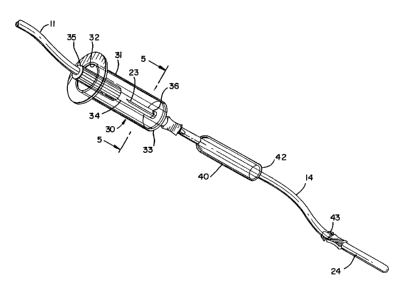
In the system of the invention, as shown in Figures 4-10,
the sealed needle joint 13 of the prior art is replaced with a
separable connection 30 including a Vacutainer type barrel 31
having an open end 32 and a closed end 33. Althou~h the sepa- -
rable connection is shown as frangible, it may take a different
form such as a threaded or bayonet connection. Needle 23
connected with distal tube 14 extends through the closed end of
the barrel where it is fixed and is confined within and
shielded by the barrel. It should be noted that the Vacutainer
brand barrel 31 is a modified version of one component of a two
part system by Becton-Dickinson Corp., in which the barrel
normally has a needle fixed in the closed end, and a glass test
tube with a rubber seal in the open end is adapted to be in-
serted in close-fitting relationship in the barrel so that the
rubber seal can be pierced by the needle carried in the barrel.
The barrel 31 in the present invention eliminates the needle as
conventionally used on the prior art apparatus, and instead
incorporates the needle 23 carried on the distal tube 14.
A rigid, frangible tube 34 is permanently affixed at one
end to the closed end of the barrel and extends coaxially
through the barrel to a knurled grip 35 which connects the end
of the frangible tube with the distal tube 11 and which
projects beyond the end of the barrel so that it may be grasped
to break the frangible connection. A threaded or bayonet
connection may alternatively be utilized. Thus, blood drawn
from a vein of the donor through needle 15 is enabled to flow
through the distal tube 14, frangible connection 30 and distal
tube 11 to the blood bag 12.
When the blood bag is filled, the distal tube 11 is clamped
and the knurled grip twisted to twist the tube 34 and break it
at weakened area 36, thereby exposing the needle 23 within the
1334918
barrel. Vacutainer brand test tube "T" are then inserted into
the barrel into operative relationship with the needle 23 so
that they can be filled with blood for various screening tests.
The needle 23 thus remains shielded at all times from contact
with health workers, eliminating the danger which is presented
by exposure of this needle in prior art devices. During thi~
time, the needle 15 remains inserted in the vein of the donor.
The tube 14 may be clamped to stop the flow of blood while
changing test tubes.
After the test tubes are filled, a pressure dressing "D" may
be placed over the venipuncture site and needle 15 withdrawn
from the vein of the donor. Prior to removal of the needle,
however, a tubular shield 40 is moved from its retracted
position adjacent the frangible connection 30 to a position
immediately adjacent the venipuncture site. The tubular shield
40 has a relatively narrow opening 41 in one end, closely
surrounding the distal tube 14, and a wider end 42 which is
adapted to slide over the needle 15 and associated components.
The length of the shield is such that it will project beyond
the sharpened end of the needle 15 when it is slid fully down
over the needle. A detent 43 is formed at the juncture of
` needle 15 with distal tube 11, to lock the shield 40 in place
over the needle 15 after it has been slid down over the needle.
Further, as seen in Figure 12, the shield 40 may be radially
slit around the opening 41 to facilitate movement of the shield
over the detent 43. Thus, health workers are protected at all
times against exposure to the sharpened point of needle 15. A
plug or cap, not shown, may additionally be fixed to the
opening 32 to further protect against injury. Said cap or plug
may be hinged or otherwise attached to the barrel 31.
A butterfly or winged needle could be used in lieu of the
needle 15, if desired, and rather than the slidable tubular
shield 40, a shield envelope may be used.
'~,
--7--
1334918
A different form of prior art blood collecting system is
shown by Figure 13 which employs only a distal (donor) needle.
Referring to Figure 13, the bag is first filled with
blood. Thereafter, non-heparinzed blood is expressed back
through the tube 44 only through the needle 45 to fill sample
test tubes.
Figures 14, 15 and 16 illustrate an embodiment of the
invention useful with a single needle blood collecting system
of the kind illustrated by Figure 13.
Referring to Figure 14, a modified vacutainer barrel 46 is
provided with means 47 for engaging tube 44 at its upper end
and with an open lower end 48 for the receipt of vacutainer
test tubes. The means 47 for engaging the tube 44 is recessed
at 49 to receive the top side of the needle shank 50. The
tube 44 is provided with detents 51 spaced above the needle
shank.
Figure 14 shows the tube 44 filled with blood. The
vacutainer barrel 46 is positioned on blood-filled tube 44 a
substantial distance above the needle shank 50.
Figure 15 shows the vacutainer barrel 46 moved downwardly
over the needle 15 and locked into position by the abutment of
the top of the needle shank 50 with the recess 49 in the upper
tube engaging means 47. As shown in Figure 16, open end 52
with radial slits 53 provide a tube engaging means to allow the
lock to engage detents 51.
With the vacutainer shield locked into the position shown
in Figure 15, blood may be drained retrograde from the tube 44
to fill sample test tubes without risk to health workers. The
-8-
133491~
modified vacutainer barrel 46 functions as a combination needle
shield and test tube receptacle. A plug or cap, not shown, may
additionally be fixed to the opening 48 to further protect
against injury. Said cap or plug may be hinged or otherwise
attached to the barrel 46.
Although the invention has been described with reference to
particular embodiments, it i6 to be understood that this
embodiment is merely illustrative of the application of the
principles of the invention. Numerous modifications may be
made therein and other arrangements may be devised without
departing from the spirit and scope of the invention.