Note: Descriptions are shown in the official language in which they were submitted.
1 334981
Hospital Bed for Weighing Patients
Background of the Invention
This invention relates to a hospital bed,
and more particularly, to a hospital bed having the
capability of measuring and maintaining a record of a
patient's weight as well as changes in the patient's
weight.
The bed of the present invention has its
principal use in intensive care or critical care units
of a hospital. There, it is necessary to monitor
vital functions of a patient on a regular basis. Some
must be monitored continuously. One of the vital
functions that must be measured on a regular basis is
the patient's weight.
Since the patient's health is in such a
state that the patient is required to be in intensive
or critical care, it is highly likely that the patient
cannot leave the bed for a weight measurement and that
the patient probably should not be subjected to the
.k.
I 33~981
-- 2
trauma attending moving the patient to some sort of scale.
Patient weighing has been done in various ways.
A cumbersome sling overlying the bed has been provided, and
it has been necessary to move the patient onto the sling
and to lift the patient, by means of the sling, off the bed
to effect the weighing operation.
Thin weighing scales adapted to be slid under the
patient have been disclosed. See U.S. Patents Nos.
3,217,818 and 3,463,368.
A weigh system forming part of a bed assembly has
been disclosed in U.S. Patent No. 4,015,677. Since there
is practically no bed structure disclosed, it is assumed
that the total bed and patient are weighed.
It is known that Stryker Corp. of Kalamazoo,
Michigan is marketing a bed having a weight monitoring
capability, but not much is known about how the weighing is
accomplished. The literature indicates that there are
provisions for changing tare to accommodate things added or
taken from the bed. Aside from the background art
heretofore disclosed, there is little art relating to weigh
beds.
summarY of the Invention
In accordance with an embodiment of the present
invention there is provided a hospital bed comprising: a
base; a rectangular support frame mounted on the base, the
support frame being rectangular in cross-section; a
rectangular weigh frame overlying the support frame, the
weigh frame being formed of spaced parallel frame elements
of an inverted U-shape in cross-section; the support frame
being nested within the inverted U-shaped weigh frame
elements; a load cell at each of the four corner portions
of the weigh frame connecting the weigh frame to the
support frame.
~ .
~.
~ 1 ~ 3 ~
In accordance with another embodiment of the
present invention there is provided a weigh apparatus
comprising: a base; a rectangular support frame mounted on
the base, the support frame being rectangular in cross-
section; a rectangular weigh frame overlying the support
frame, the weigh frame being formed of spaced parallel
frame elements of an inverted U-shape in cross-section; the
support frame being nested within the inverted U-shaped
weigh frame elements; and a load cell at each of the four
corner portions of the weigh frame connecting the weigh
frame to the support frame.
In accordance with a further embodiment of the
present invention there is provided a hospital bed
comprising: a base; a support frame mounted on the base;
a weigh frame disposed above the support frame; a plurality
of load beams connecting the weigh frame to the support
frame; each load beam being fixed at one end to the support
frame; a swivel connection between the other end of the
beam and the weigh frame, the swivel connection being a
rigid vertical element having a circular housing at each
end, a ball movably-mounted in each housing and having a
bolt projecting axially from each housing to create a ball
joint on its upper and lower ends, the upper ball joint
bolt being connected to the load beam and the lower ball
joint bolt being connected to the weigh frame, whereby the
weigh frame has freedom of movement in any direction in a
horizontal plane; and means for monitoring changes in
weight on the weigh frame as detected by the load beams.
According to another embodiment of the present
invention there is provided a hospital bed comprising: a
base; a rectangular support frame mounted in the base, the
support frame being rectangular in cross-section; a
rectangular weigh frame overlying the support frame, the
weigh frame having spaced parallel frame members of an
,~
_ 4 ! 3 3 4 9 8 t
inverted U-shape in cross-section; the support frame being
nested within the weigh frame; a load beam at each of the
four corner portions of the weigh frame connecting the
weigh frame to the support frame; each load beam being
fixed at one end to the support frame and cantilevered from
it to provide a free end; and a swivel connection between
the free end of the beam and the weigh frame, the swivel
connection being a rigid vertical element having a circular
housing at each end, a ball movably mounted in each housing
and having a bolt projecting axially from each housing to
create a ball joint on its upper and lower ends, the upper
ball joint bolt being connected to the load beam and the
lower ball joint bolt being connected to the weigh frame,
whereby the weigh frame has freedom of movement in any
direction in a horizontal plane; and means for monitoring
changes in weight on the weigh frame as detected by the
load beams.
A still further embodiment of the present
invention provides for a weigh apparatus comprising: a
base; a rectangular support frame mounted on the base, the
support frame being rectangular in cross-section; a
rectangular weigh frame formed of spaced parallel frame
members overlying the support frame and being of an
inverted U-shape in cross-section; the support frame being
nested within the weigh frame; and a load beam at each of
the four corner portions of the weigh frame connecting the
weigh frame to the support frame; each load beam being
fixed at one end to the support frame and cantilevered from
it to provide a free end; and a swivel connection between
the free end of each beam and frame.
In accordance with yet another embodiment of the
present invention there is provided a weigh apparatus
comprising: a base; a support frame mounted on the base;
a weigh frame disposed above the support frame; a plurality
- 4a - ~ ~4~
of load beams connecting the weigh frame to the support
frame; and means for monitoring changes in weight on the
weigh frame as detected by the load means; wherein each
load beam connection between the support frame and the
weigh frame comprises: a load beam fixed at one end to the
support frame; and a swivel connection between the other
end of the beam and the weigh frame, the swivel connection
being a rigid vertical element having a circular housing at
each end, a ball movably mounted in each housing and having
a bolt projecting axially from each housing to create a
ball joint on its upper and lower ends, the upper ball
joint being connected to the load beam and the lower ball
joint bolt being connected to the weigh frame, whereby the
weigh frame has freedom of movement in any direction in a
horizontal plane, and can be tilted to move the weigh frame
to a Trendellenburg position without affecting the weight
detected by the load beams.
In a preferred embodiment, a weigh frame that
contains the patient supporting surface is mounted at its
four corners by load cells to a bed support frame. The
weight from the four load cells is summed, as will be
described below.
Each load cell may be fixed at one end to the
support frame and at the other to the weigh frame by
universal swivels having upper and lower ball joints.
Thus, the weigh frame "floats" with respect to the support
frame and does not bind, thereby eliminating possible error
in the weighing function.
In a preferred feature, the weigh frame is an
inverted U that telescopes over a support frame that is
preferably formed of a hollow rectangular section tube.
~ 33~9~ ~
the depending legs of the inverted U provide points of
attachment for the connection of the weigh frame to the
swivel joint and thus to the support frame. The
relationship of inverted U weigh frame and the
rectangular tube support frame provides freedom of
vertical movement of the weigh frame while restricting
horizontal or lateral movement, thus providing a stable
support of the weighing assembly with respect to the
support frame and lower bed structure.
In another preferred feature, a four panel patient
support surface is mounted entirely on the weigh frame.
Pistons and cylinders connect the support surface to the
weigh frame to permit normal articulation of the four
panels to permit the patient to assume the conventional
reclining and sitting attitudes associated with hospital
beds. The system for providing pressure to the pistons
and cylinders is mounted on the lower base frame and does
not form a part of the weight applied to the load cells,
with flexible hoses being provided to connect the
pressure system to the pistons and cylinders that operate
the patient support surface.
In another preferred embodiment, the support frame
projects at both of its ends beyond the weigh frame. The
projecting portions of the support frame carry
accessories such as infusion pumps, I.V. bags, drainage
bags, head and foot-boards and the like. By mounting
those accessories on the support frame, the adjustments
of tare are minimized and the monitoring of the patient's
weight is more accurate. For example, with the drainage
bag off the weigh frame, the loss of fluids by discharge
from the patient into the drainage bag is accurately
reflected in loss of patient's weight. Similarly, by
mounting the I.V. bag off the weigh frame, increases in
the patient's weight by virtue of the introduction of the
.
- 5a - ~ 33~81
I.V. fluids is accurately monitored.
The invention provides for changes in tare even when
the incremental change in tare is unknown. In a
particularly preferred embodiment, alarm options may be
provided including an alarm at a remote location such as
a nurse's station, an illuminated alarm, an audible alarm
and no alarm. The alarms provide notification of the
patient's exit from the bed, which is particularly useful
for patient's whose acuity is impaired. The patient's
loss or gain of a predetermined amount of weight can be
programmed to operate the alarm. The invention provides
for displaying of weight in either pound units or
kilogram units. All of the controls for the scale may be
battery-operated and the weight control system provides,
on its display, an indicator for low battery supply.
Brief DescriPtion of the Drawings
The several features of the invention will become
more readily apparent from the following detailed
description taken in conjunction with the accompanying
drawings in which:
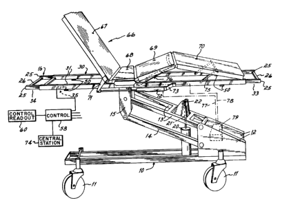
Fig. 1 is a perspective view of a bed employing the
present invention;
Fig. 2 is a perspective view of the support frame
and weigh frame combination;
Fig. 3 is a cross-sectional view taken along lines
3-3 of Fig. 2;
Fig. 4 is a cross-sectional view taken along lines
4-4 of Fig. 2; and
Fig. 5 is a plan view of the display for the
control/readout unit associated with the weigh scale.
The bed to which the present invention is applied is
shown in Fig. 1. That bed is more fully described and
claimed in U.S. Patent No. 4,751,754, issued June 21,
1988.
-6- 1 3 3 4 9 8 ~
The bed has a base frame 10 that is support-
ed on casters 11. Bosses 1 fixed to the base frame
pivotally support the ends of a cantilevered support
arm 13 and a stabilizer arm 14. The ends of the
cantilevered support arms 13 and the stabilizer arm 14
are pivotally connected to a bracket 15, thereby
providing a parallelogram linkage support for the bed.
The bracket 15 is bolted to support frame 16. A
piston and cylinder 20 driving a piston rod 21 i~
mounted on the base frame 10 with the piston rod 21
being connected to the support arm 13 by means of a
clevis mount 22. Actuation of the piston and cylinder
20 causes the piston rod 21 to extend and contract,
thereby raising and lowering the parallelogram linkage
and the support frame 16 of the bed.
Referring to Figs. 1-4, the support frame 16
consists of two tubular rectangular section beams 25
joined together by transverse bars 26 mounted at each
end of the beams 25. A weigh frame 30 is mounted on
the support frame 16. The weigh frame consists of two
inverted U-shaped beams 31 that are shorter than the
rectangular beams of the support frame. The rectangu-
lar beams of the support frame are nested within theU-shaped beams of the weigh frame with front and rear
portions 33 and 34 of the support beam projecting
beyond the weigh frame 30.
.
.
7 1 334981
At each corner of the weigh frame 30, the
weigh frame is supported on the support frame by a
load cell 35. The load cell is an elongated element
36, containing a strain gauge, not shown, and having a
boss 37 connected by bolts 38 to the inside of the
rectangular beam 25. Thus, the major portion of the
load cell is cantilevered from the boss 37 presenting
a free end 39. The free end 39 is connected to a
swivel 40 by means of a bolt 41 threaded into the free
end 39 of the load cell. The projecting end or head
of the bolt 4i is a ball 42. The ball sits in a
housing 43 to form a ball joint. The housing has a
female thread 44 that is connected to a male thread 45
on a second housing 46. The second housing 46 re-
ceives a ball 47 to form a second ball joint. Theball 47 is mounted on a pin 48 that is secured to a
clevis mount 49 on a bracket 50.
At each corner of the weigh frame flanges 55
project laterally. The brackets 50 are bolted to said
flanges 55 across the open end of the U-shaped beams
31. Thus, each swivel mounting securely connects the
free end of the load cell to the weigh beam 31. The
swivel connection permits limited universal movement
of the weigh frame in the horizontal direction,
thereby preventing any binding of the weigh frame with
respect to the support frame. Preferably, a set screw
56 is provided in free end 39 to limit the movement of
the load,cell in a downward direction while permitting
-8- 1 33~9~
the load cell to be stressed to the point of reflect-
ing a weigh level well beyond the expected loading of
the corner of the weigh frame, thereby preventing
damage to the load cell. The lead cell is provided
with suitable strain gauges configurated into a
Wheatstone bridge as is conventional. The strain
gauges are connected to a computerized control 58
which in turn is connected to a control/readout unit
60, to be described more fully below. The output of
the strain gauges are read sequentially and then
summed to provide the total weight on the weigh frame~
The weigh frame has two laterally-projecting
brackets 65. A patient support 66 having a head panel
67, a seat panel 68, a thigh panel 69 and a foot panel
is secured by means of the seat panel to the
brackets 65 and, hence, to the weigh frame. The head
panel 67 is hinged to the seat panel 68 and is con-
nected by a bracket 71 to a piston and cylinder 72
which is secured to a bracket 73 on the weigh frame.
Thus, the piston and cylinder 72 on the weigh frame
causes the raising and lowering of the head panel 67.
The foot panel 70 is pivotally connected to
a bracket 75 which is pivoted to the weigh frame. The
foot panel is hinged to the thigh panel 69 which is in
turn pivoted to the seat panel. A piston and cylinder
76 connects the thigh panel to the weigh frame. The
pistons and cylinders 72 and 76 are connected by
hoses, diagrammatically indicated at 77 and 78, to a
1 334981
g
hydraulic system 79 mounted on the base frame. The
manipulation of the panels of the patient support and
manipulation of the support frame are all performed in
a manner as described in U.S. Patent ~To. ~,751,754
issued June 21, lg88 and forms no part of the present
invention except to note the pistons and cylinders for
operating the patient support panels are mounted on
the weigh frame and become a part of its tare whereas
the hydraulic system including pump and fluid reser-
voir is mounted on the main frame with only hosesbeing connected between the two. It should b~
understood that the manipulation of said panels could
be performed using electric motors mounted on the
weigh frame and a power source mounted on the base,
lS with conductors connecting the power source to the
weigh frame.
The portions 33 and 34 of the support frame
that project beyond the weigh frame provide elements
directly connected to the main frame for supporting
accessories such as infusion pumps, I.V. bags, drain-
age bags, headboards and the like. All of those
accessory elements are thus supported separately from
the weigh frame and the weighing system.
The bed as thus described will be outfitted
with a mattress, sheets, pillows, blankets, and the
like. These items become part of the tare. When
these are varied, as by adding a blanket or removing
pillow, the tare can be changed, whether the weight of
-lo- 1 3 3 4 9 8 1
the items be known or unknown, by following an easy
sequence of steps on the control/readout unit 60.
Further, an attendant can set the controls to provide
an alarm, visual or audible, to warn an attendant that
the patient has lost or gained weight beyond prede-
termined limit, or that the patient has left the bed.
Since IV bags and drainage bags are supported on the
support frame 16 and/or bracket 15 and are thus out of
the weighing system, losses from the IV bags and gains
in the drainage bag do not influence the determination
of the patient's true weight.
The alarm is adapted to be connected to a
central nurse station 74 so as to initiate an immedi-
ate response to an emergency situation such as a
patient's falling or climbing out of bed; or a delayed
response for weight gain or loss beyond the pre-set
limit.
The control/readout unit 60 is preferably
mounted on the front or foot end of the bed convenient
for reading and manipulating by the attendant.
The panel has a liquid crystal display 80
that will display the numbers indicating the weight
and will display the weight units as KG or LB. The
units, KG or LB, are set by the units key 81. The
display will also show one of four modes: OFF, EXIT,
WEIGHT (+), WEIGHT (-). The monitoring mode is
selected by mode key 82. The display will also show
the alarm which is one of three alternatives: silent,
-11- 1 3349~
local, remote. The alarm condition is determined by
the alarm key 83. Four digits are displayed to
reflect weight. These digits are controlled by four
digit stepping keys: 85 for tenths, 86 for units, 87
for tens and 88 for hundreds. The hundreds key
sequences the display through 0, lO0, 200, 300, 400,
-400, -300, -200, -lO0, -0, +0. Thus, by proper
sequencing of the hundreds key, the units can be
changed from plus to minus.
A read key 90 is provided to activate a
weight reading. A zero key 91 is provided to activat~
a tare reading or effect tare adjustments and a set
key 92 is provided to activate monitoring controls.
The key functions are set forth more particularly as
follows:
READ Initiates 5 to 8 sec weight measurement upon
release.
Causes display "~" and preset units, either
LB or KG, as previously set, to blink upon
closure and while measurement is in process.
Signa]s measurement display with a chime.
UNITS Always comes up in previously set units.
Alternately displays in LB or KG upon
contact closure.
Freezes display when activated
and held during weight display.
J ~
-12-
Resets 10 sec. display-hold-timer upon
contact opening.
ZERO *Initiates automatic zero-tare of empty bed
when held while touching READ.
*Activates digit stepping keys for entry of
known tare change, plus or minus, when held.
*Increments total tare value by difference
between display and memory, when activated
and held during display while then touching
READ.
Recalls total system tare value when acti-
vated and held; displays for 10 sec after
release, or until cancelled by READ or SET.
*All tare operations are protected from
accidental change by dual-key or sequenced
operation.
SET Activates display when held, to show exist-
ing alarm weight value for monitoring modes.
Activates digit stepping keys when held, to
allow setting or changing existing alarm
weight value.
Eacilitates MODE and ALARM setup when held,
by activating display when display is
otherwise inactive. Releasing SET causes
display to clear.
S a r
13 l ~3~98 1
Provides memory recall of last weight when
held while activating READ.
MODE/OFF Seiects monitoring mode, shown in display,
and as described:
OFF: Automatically timed monitoring
functions inactive.
EXIT: Rough weight measurement (+ 0,
-10~ accuracy) taken every 3 to 4
seconds.
Places EXIT alarm if weight
falls below existing alarm-weight
value for two successive
readings.
WT-: Precise weight measurement (+1%
accuracy, +0.1% repeatability)
taken every 10 minutes. Places
weight-loss alarm if weight falls
below existing alarm- weight
value for two successive
readings. Last weight value is
stored in memory for recall.
WT+: Precise weight measurement (+1%
accuracy, +0.1% repeatability)
taken every 10 minutes. Places
weight-gain alarm if weight
exceeds existing alarm-weight
~ .?~ . s~ /d ~ X~i~ *~
~ 33498 1
-14-
value for two successive readings.
Last weight value is stored in
memory for recall.
Cancels alarm with single touch; requires
resetting, as before, to re-arm monitoring
mode.
Sequences through available settings in
rotation with each touch, or rolls at a 1/2
sec. rate if held for 1 sec.
Skips settings that are not available due t~
hard-wire inhibit or programmed inhibit.
Settable any time a full display is present,
that is, during weight display holding time,
during total tare display holding time, or
any time SET is held activated.
ALARM Selects alarm type, shown in the display,
and as described:
SILENT: Flashing yellow LED on Nurse
Panel Facade.
LOCAL: Flashing yellow LED plus audio
beep from Nurse Panel.
REMOTE: Flashing yellow LED plus
room-cancellable call with
identifying audio beep
transmitted through SIDECOM to
nurse station.
~ 33~98 ~
-15-
During all alarms the preset monitoring
condition (EXIT, WT-, or WT+) flashes in the
display to identify the type of alarm
placed.
Audio tone for EXIT is 400 Hz gated ON for ~
sec., OFF for ~ sec., for WT+ and WT-, a 400
Hz tone gated ON for ~ sec., OFF for l~ sec.
The LED and DISPLAY flash at the same ON/OFF
rate as the audio.
Yellow alarm LED burns steadily anytime a
monitoring mode has been set; then flashe~
upon alarm.
Sequences through rotation from SILENT to
LOCAL to REMOTE to SILENT with each touch of
the key, or rolls at a ~ second rate if held
for 1 second.
Settable any time a full display is present,
that is, during weight display holding time,
during total tare display holding time, or
anytime SET is held activated.
Alarm placement occurs within ten seconds if
! the set weight, when entered, is already in
the alarm condition when the SET key is
released. This alerts the staff while still
in the room.
DIGIT Four (4) digit stepping keys, each
KEYS associated with a single decade numeral of
-16- ~ ~34981
the display, are used to increment the
display for ZERO and SET, when either of the
latter keys are held.
Dual key activation reduces the opportunity
for accidental changes in tare resulting
from touching a wrong key.
Hundreds se~uence is +0, +1, +2, +3, +4, -4,
-3, -2, -1, -0, etc; tens, units and tenths
step incrementally from 0 to 9 and then jump
back to zero without a carryover into the
next decade.
Digits step with each touch of the key, or
roll at a ~ second rate if held more than l
second.
BAT Annunciator flashes in display when charge
is within 5 to 15% of depletion. Scale is
fully functional yet with this reserve, and
! meets all accuracy requirements. Automatic-
ally places a nurse call every 10 minutes
when BAT display is activated.
NOTE: In tare or recall operations involving
holding ZERO or SET while momentarily
activating READ, there will be a tendency to
releas~ simultaneously. To prevent
activation of an unintentional function when
READ is released last, controls are designed
such that if READ opens last, but within ~
-17- l 33498~
sec. of ZERO or SET opening, the operation
will not be affected.
The steps in the various procedures for
weighing the patient, changing the tare,.changing the
alarm, etc., are as follows:
-18- 1 3 3 4 9 8 1
W
o
W
~ C
W
~ ~ ~ cn
.~ C o ~
~ ' ~ ?Y
:~ ~ I W 3Y
I ~J l o
o z:
1_ ~ + ~ ~ + + ~ + 3 ~
- O ~ O O ~ ~3 ~ H
~ ?Y ~ o o ~Y
3 O O ~n ~
~ O O C C 3Y
~3 c ~3
., c 1-
H~
C ~ t ~ ~ W ~ ~ t~ ¦ ~ ~ C1 I N ~
1 O ~D -- Z 1 H O O ,~:t~ 1~ t~ ~ ~. ~ ~3 O P~ 3:
U~ ~ ~ O H ~ 1 ~~ ~ It U~ ~ C U2 ~
W D " ~ W ~Y 1 3O 1 tD ~ O ~ ~ O tn ~Y P. ~Y
n - _ Y ~ t ~ C PJ
,0~ 'D K 3 1~ ~ P~ 1-- . K 1-- Q~
~ U tD ~ (D V t~ U ~--
?Y ~ -- J 'D--~ U.
3Y u ~
,~ r n n rn ~ ~ C ~ un
Pl C U~ 1~- ~ r ~D n
I c t~l IJ rn ~ ul P- ?Y (D
r: ~3 0 ~ O~ ~ ~ ~ :1 u~
~ u e~ ~r~ ~ t~ rn t~
O un ~ ,~ ?
t tD O 1~ t~
t5~ O ~ t~ W ~ H PJ
rn ~ ~ H rto --~ t~ r
rn ~ ~ ~ D H tD
rn tD ~ ?Y O 3~ 0 ~ ~n O O ~ ~3
.. ~ ~ ' I rn H
r~ rn . ~ rt 3~ '3
O--~ un O Pl t~ O
4 un un t~
3 ~: 1-- 3 Ul ~n ~
0 ~ ~ ~ o
:5 It O It ~ 3~
~ ~ ~ 1-3 tD O N
O H1 ~D ~) 3~
o ~ u~ ~
-19- 1 ~3~98~
1~ H !:a
~Z P~
C ~ t1
~3 ~
U.
Z: U
0~ ~
O ~ H ~
3 H ~ ~Z I O C
-I ~ G~~ii; ~ ~ t.~ C
~ U~ C '~
y t 1-3 C) 1-3 7
c~
U` :~
t~ I t H O ~
t~ h ~ 3 O
~ h '3 U~
O _~ I_
I + Z ~3
+ ~ I+æ + ~ + ~
o ~3
U~ ~ U~ ~ tl U~
U~ ~C
C
~3 C C ~3 C l--
~h ~. .
C C ~ ~ + U~ 3 ~ ~ ~ W ~3
O rt ~ rD 1~ ~t C I-- ~1) H 'S H 1'- 0 1--O ~ 1-- ~ H) t~ O
'~ H ~t un 0 ~~ U~~: U~~ U~ un ~3 un ~1--O H rt
r~ ~ W ~ rq ~3 ,~ (D
: U~q 1~ Uq t. 1 + rt t ~ t. ~ 1~ W 1-- ~ Uq ~3 It t~
K W ~ n - 1
t-- ~ rt ~ U~ ~ u ~- K r- K ~ K !`C rr ~: ~ rD r,'D ~ ~ ~ r~
5 1 ID ~ ~3 K ~ (D K ~ p- `- 5 D t~ K
P), ~ 1~- u ~ r ~ o ~ ~ u IJ O --r~ U
+ ~ O ~ Y ~ t ~
I~ + k. ~ ~ 1--~ r ,k ~ tD ~ 1~ - k
U ~D ~ O O ~ 3~ - r- rn 1-0 ~D ~ un ~D U~ n ~D
r~ ~ ,5 ~ 11 '~, 11 ~ ~ 0 ~ ~ W fD
'D un P~ 4 ~ r ~un ~ 3 3 P~
I- C ~, (D ~ -- D ~ ul ~ ~ ID'5 1-- r- ~ 1
r~ , O rn ul w ~ ~ rt~ ~ O ~ ~
ul ~ W ~ (D 1 ~ r~ ~ W t~i PJ un ~ ~, W
~- rn ~ - ~ ~ ( '5
p~ 5~4 D ~ -- H~ O 1~ 1- ~ O ~t-
o r ~ ~ - W ~ ,- ~3 'D H ~ O ~ rn
rn W rt ~ ~ Hrt rn ~ - lJ C 1 ~ rD un ~ ~
rn ~ rD ~ r~ rt1~- t !Z --H un 1~- un 1
D 1. ~ It ~ ~ It ~5 ~'5 ~ H 0 ~3 un ~D ~ ~, ~.
- t.~~ O ~D ~ 3 u H (D ~ n
n o ~ - u~ ~ ~ rt n C O ~
~ It 'D 1~ I ~ ~ O rn P~ ~ ~ - tt ~ 1 It --
rt -- ~ u~ un e ID ~ '5 ~ rt -- , ~
U~ ~D ~ ~'5 It I'~ r ~t~ ~ '. 1--~:
E3 ~ W lt ~ Uq + O 1- ~h ~D un It ~ ~ O ~D
tD ~3 n D K I It ~ 1_~ . tD _
It O ~D n ~o ~ D It ~ It O --un
h (D ~ rn ~ ~ ~D (D ~:
O rt ~ + It ~ O
O ~t~ O
It
-20- 1 3 3 4 9 8 1
H
C
,.~.
O ~ C
C ~ ~J H Y C~
C ~ ~3 ~ C
G~ .~ O .~ ,.
~C
~ Y l-3 H ~
t'3 ~ ~ Z W
:~ o--
p ~ O
-- C ~
C
~ ~ +
+ o ~ ~ ~
~ . ~ ~ +
C ~
C C
3 ~1 ~ ~ ~ 3 ~ X ~ ~ C 31~n rn ~ ~ t~ ~ O
~ C ~ o ~ - un ~ ~ Ul ~ _ ~ H 3 ~ 3 H - O r~ 1~ rn u~
'5tq ~a -~ ~ ~ tq 'D U ~3 0 ` un H C~ ~ '5~ ~ ~ t~l
C ~t ~ ~ pJ tD r~ n ~ t ~ r~
z: vn ~ ~1 ~ o ~ r ~ rt o ~3 vn~ t~
E3 ~ ~ 3 p.
~ ~ ~ ~ ~D ~ vn ~ ~ 'D ~
C~ O Y 1- - 5 ~ ~ Y
~; J n ~7 Q '- ~ n~ H vn ~J n ~ a ~- ~
-- rD -- J ~ o ~ Y v ~ Y
~n ~ ~ t ~~1~ ;~ ~ 5 ~ t n
r~ 3 n tD 3 PJ ~3 3 r7 3 n 3
O ~ t (D 3 ~ ~1~ r 1-. tD O- (D P- E3
vl 3 1 vn :~ 3
~D 3 ~ r o ~1~ - (D 3 ~ tr
H ,~ D rn ~--n ,t (D ~q (D
rn--~
:~ O n --Ul 3 rn(D P- ~ 'D -- o rn --~n rn
3 O ~I
'D H~ 3 Q rt 1-- rn ~ P- ~h 3
~, ~ rn co o ~ tD u ~o
r ~ ~ r~ It It3 ~: 1' ~ r It
: ~ ,t p~ rn ~ ~ o ~ ,t ~ rn 1~-
t (D ~ ~It O rt ~ It
H ~ O (D ~ ~ O r~ H r
rn . P. o 1~ ~ rn -
Z :~O o Z
~3 It s 3
-21- 1 334981
H
G)
H
~3
G ~ C O C
~ H
Y 3: Z
:n ~ C~
¦ ! ~ N ¦ ~ H
UJ ~ + ~ + ~ U~ :~ + 3:
+ ~D 0 ~3 I-d
(1 ~ +
~ u~
C' 1~ ~3 q ~ 1~ C
o o
~h
3 ~ ~ ~ ~ O C ~ ¦~rn ~ C '
~D --O t~ O ~ ~ t'~ O t~
Rl '~ t~ U U~ Cl -- O H ~ ~ ~ C ~ H tD 0~ ~ pl 1~ H ~ ~ ~3
t'3 ~ rl ~3 ~ C~ t'3 ~ U~ ~ I:~i. 1- ~ ~ ~ ~: H
t 1~ 1~ U~ U I~ ~ ~ I~ t~ 1-~ U~
rD ~ D :0 - ~ Pt )D ~ PJ ~ t~ D ID 1~ Z
3 ~ rn ~ 5 ~ t P~
~ rl ~3 Q, un tD ~ ~ Y Y ~
r~ r ~ 1- J~ t~~D ~ tJ' ~ O ~ O : ~ ~ O n rn ~ c'
rn ~ ~ u~ J ~ rn ~ C 1~ U~
G ~ rn ~ o
D t: ~ ~ ~ t~ ~ Z t C 3 tD D 1--~ C
1~ ~ O 1- O t~l ~D rD ID 'D ~ ~ O ~ 1~ t~i rn z
O rt rt ~: 2 ~r~ ~ D U ~ ~ 1~ ~-- E3 ~
v~ + PJ rn ~ n ~ K (D 1~ :~ vn ~ ~ O tJ t:~ I Z
~ ~ u ~ rt ~3 W Pl ~ rt ~ tD Q
It !~ '0 ~ ~ 1 0H C ~ 0 ~ 2~
~ W 11 pl ~o (~ C 11 C~ Z
_ ~ ~J rn :t~D rQo 1~- t ~ ~_3 ~ O ~ ) --~ O
3 t1: ~D ~ v~ U~ ~ v~ O O ~ ~ q u~
~ - ~ vn (D :2. W ~ 3 ~ rn r ~ W S~
n t~ ~3 C ~ ~ ~ + H~ (D O ~ ~3 C ~
n :~ rt ~ W
3 111 5:h C~ ~ rt rn ~ -- ~3 O
r~ ~5 C ~ ~ rt ~ ~ u. -- ~3 v lD ~
rt ~S C ~ -- r~ Kr ~ ~ 'D L_~ rn
0 ~ 3 ~ PJ ~ : U I . - ~ ~
-- 3 o ,-~a n Ivn
~n o . o
h~ O O
o I
-22- ~ ~349
o
t~
;r
un
.~ ~
t~ .
~: O ~ O C
t' ~ ~ c
I rn n C
Z Z
C ~n ~H
H un
~ rn
+ ~ 3 rn ~ + ~ ~--~ un ~ + 3: ~~
u - ~ 3
rn. (~ I rn- ~i
C ~ C 1~ C ~ I~ C
0 3 ~ W 0 ~ G -- C P~ C 3 rn U~
(1) P1 H ~ H t-- '~ -t 'D H l-h ~ ~5 1' O ~ t~
rn ~ rn PJ j rn ~ n tl --o H ;3
+ P~ O ~ ~ t~ ~ ~ 0 rn n ~ 0 ~ rt ~ W ~ U ~3 0
C ~ ~ ~4 t' r --rt w ~ ~ ~ ~ 0 1- 1~: un
O ~ ~ ~ 1~ tD ~ u~ - ~ - r~ n - ~ 5~\ .
~ It O P~ I-C ~ ~C ~ t~ K ~ 1-- U ~ t~ 'D t~ r r~t O ~ 0
3 ~ 1-- Pl tD ~ O t~ O t~ ~ ~ ~- ~ It 3 IJ
Pl C C C t' t~ Q~ It '5'5 r~ '5 u ~ tD
tD C C ~ P~ O~- p) ~ Y1~ ~ 5 ~: W P~
~- 1~- - ~ 1'- 1-- C I-- 1'- ~ t[ --~ tt C ~- ~ H U 11
p) !t pJ 0 ~ 4 3 Y U ~ '~ rt t~
3 Hl ~ t ~,. 0 3 r 0 5 ~ 3 p, ~ 5 ~ tr n
O r ~ ~ c I~ O rt 3 0
tD tD ul r.~ 5 ~ ~ O1-- PJ _~ 3r~ t ~ - tD O
- rt 1~- tD C P~5 ~ 1~ pJ t 3 i 0 ~ 3
rt ~q ~ C 1~ 0 0 ~ tD ~ rt~
O r5 15 ~ C ~ ~q ~ tD P~
~S rt rt O Z '5 - t~ J ~ ~J O r~ - tD
t3 ~t~ Z H Y rt r 1~- - rt _ tD 0 rn rt ~ n r
~q 'D ~C (~ H un Y ~ 5 ~ 0 tD ~ t~ 'D ~ O
11 ~3 -- ~3 ;~ Pl ~D H~ 1 tDt~ 1~- r
3 ~ rn3 1~ :~ rt ~ D 0 rt 0 3 ~
O . tD U C tD tD ~ tD ~ ~ ~ tD O
tD tD - IttD tJ' 1~ . O rt P- rt I--
tD t~ ~ tDQ' ~- IPW t~D ' t ~5 1-- tD ~ Iw O ~
r~t ot ot lo ¦~ tD Hl ~t~ ot¦~ ~t H
W 0 t~ O O Z
rt lt ~3
3 4 9 8 1
--23--
~' Z
o
~Z .
~ n
Z I ~ ~3 t
~ _ y
O I
Y C 'Y ~3 t~ t~
, ~ Z O ~ + ts3 ~3
y H 1~ i~
3 U~ t X 1~3
~ ~ H H
W ~ t~ 0 ~3
~3
1+ ~ 1+ ~3 1+ ~1+ ~ 1+ ~ 1+
'Y ~ ~ ~
5 C ~ C ~: C ~ C ~ C :~ C
51 U~ ~ ~ ~ ~3: u ~ t~
r. tD 1-- rt O ~ ~ H tD 1~ ~ tD 1- '5 1--- O r~-- I~ X ~ 1--H
t~ ~ tD r~ rn rn 1--1--t ~ Y 1--1--tD rt ~ p, p~ J- r~
~ ~ t~ ~ t~i r-~: tn
~- rt '5 ~ 3 tD r tD rt 5 t 3 t~
tD '- ~ ~ tD ~ rn rn
S~ u 1~ C O O ~ ~ rn O O tD tD tD ~ 3
rn ~ ~ ~ tD ~ 4 tD
t; ~ O 1- t~ 5 ~ ~ t~ rt
r 1~ Q
r rn ~ ~rn tt rn O ~ un rt n --~4 1--p) t~ 1 rt
tD r tD ~ r ~ tD ~: tD r ~ ~ t
~ rt ~4 ~ r a ~ t~ t~ t, ~ - rr 1~ ~ 3 tD r ~ ~-
D r tD t- PJ ~ u ~I r ~ f P~ t-
1-S ~ ~ P U! ~n ~ r ~n ~: ~ tl '5 ~ 1~ ~f 1--un
O tD ~, ~ tt tD O tD tD ~: rt ~1 tD ~n t r
~1-- ~: ~1- ~n 1~ t~ ~ t~ 0 un IJ~ rn tD tJ'
nun ~n ~h C Y ~ ~ p~
~n 1~ : ,t ~n Z ~'5 O 1~ t~
~n t~ p~ r, r ~ '5 ~n r ~: ~t tD H Y rt tt ~ ;~
1-- + p ~t ~t ~ tD ~ tD tD tD ~ '5 ~ ~ n
o '5 ~ ~ It tt ~~ ~ tD C tn ~ rt rt
tD ~ ~ tt Ul ;~ r ;~ tD ~ Pl O
1--~ tD ~n ~n t~ tD tD tn '~
o + ~ C ~n P~ rt tD tt ~ r. tt tt tD
-- ~ tD t~ Pl tD r ~ ~t tD ~ ~ ~ ~ tD 1~ 1~ X ~h t t~ '5 ~ J p~
+ O ~- tD ~ -- ~ rt~- un
+ ~ O -- I~ O -- O ~n tD rt
rJ tD ~ t~
tD ~ h tD ~ ~ ~ p~ ~ ~
tt
t~ un
I
"~ si~` ~',7. -
.. . .
; _S' '', :' . '
'J '.'~ J ~Sr,
~ . ~ .
.4~ aAOq'e s'e ~asal ~ao~
~ pal~al~ aq ~snuI uoF~Fpuo~ ' ~asa
L ~a~{ ~aor~ ~o ~no~ al~UFS
;-. sl~al~ ' sln~o U~ uaT~ .
eldslp uF S~uFlq ~uF~as ~ao~ ~ ~ao~ H~LlOL ~ 0 LnHs
.~r
.. c ~ u~suF S}~u~lq ~qasIa L:~S 3:S~:~lq:I~
-- ~ S~INn ~ Fa~ ~asald pu~ sn~s
aao~ pu~ w~ UFpnl~uF ' paA~ld LM ~lq~+
Fe SF anl~A LHsIaM ~M~ uF~sFx~ n ~ as aloH LM
Al:~ue~sul ~lasIa
s~{u~lq LaS ~uls~alal ' (a~uan~as AU~
uF ) pa~alduIo~ uaaq aAE?~ s~uF~as
H9I~M W~ pu~ '~N~q~ ~aao~ la~ s as~ala~
nl~A LHsIaM ~ ~ q LM W,l~+ W
. -'as~alal uodn 's~la~uo~ ~laSIa n ~/~ a~a~ asYala~ ~
~; ` ( +LM 10
-LM) apow ~uFIo~Fuo~ ~F~e~o~n~ lo
uaulalnseaw ~ Ia~ ~uFInp Alowaw
. ~ ~.. ` O~UI pad~nq ~ a~ ~o anleA ~sel M-a+ (an~aS 9NI~na
'~''!.''-`0~ 'alnsol~ uodn s~laAuo~ ~laSIa n ~/~ a~ aL~AI~ owa~ a~)
.. ..~ ~i
~ -25- l 334981
The control system admits of the possibiLity
of making an initial setting that eliminates the bea
tare and the patient's weight. Thus, the display will
provide a continuous display of the change in
patient's weight.
It will be appreciated that while the
preferred embodiment of the invention is described in
connection with hospital beds, the invention may be
adapted for use in connection with other forms of
weigh apparatus, such as patient supporting wheel-
chairs, livestock scales, or the like.
From the above disclosure of the general
principles of the present invention and the preceding
detailed description of a preferred embodiment, those
skilled in the art will readily comprehend the various
modifications to which the present invention is
susceptible. Therefore, we desire to be limited only
by the scope of the following claims and equivalents
thereof: