Note: Descriptions are shown in the official language in which they were submitted.
1334989
-1- J-275
SURGE ARRESTER WITH IMPROVED INSULATIVE BRACKET
FIELD OF THE INVENTION
This invention relates to high voltage
surge arresters that include disconnectors,
insulative mounting brackets, metal oxide varistors,
and polymeric housings.
BACKGROUND OF THE INVENTION
In recent years, metal oxide surge
arresters for protecting outdoor overhead high
voltage electrical systems against lightning have
been advantageously provided with polymeric
weathershed housings, disconnectors, and with
insulative brackets. Metal oxide varistor blocks are
sealed within the polymeric housings, which protect
and insulate the varistor blocks against the damaging
effects of rain, snow and airborne contamination, for
example. The insulative brackets have provided
electrical insulation to allow for proper operation
of the ground lead disconnector.
Prior art surge arresters have also
included fiberglass tubes or wrappings supporting the
varistor blocks. Also, the inner diameter, or bore,
of the polymeric housings have been bonded to the
outer peripheral surfaces of the tube or wrapping.
U.S. Patents Nos. 4,656,555 and 4,404,614 disclose
some embodiments of these constructions and methods
of construction. Methods of bonding a polymeric
_ -2- 1 33~ 989J-275
housing along its bore directly to varistor blocks,
or to layers or coatings surrounding the blocks, are
also disclosed in U.S. Patent No . 4,161,012. Polymer
housings molded directly onto the peripheral surfaces
of an arrester element as well as to flat end surfaces
are disclosed in U.S. Patent No. 4,833,438. Each of
the methods and embodiments referred to in the afore-
mentioned U.S. patents involves a relatively expensive
process for achieving a seal between the inner surfaces
of an arrester housing and the outer or peripheral
surfaces of arrester components enclosed within the
housing.
A method of achieving an air free, sealed,
moisture excluding interface between peripheral sur-
faces of arrester components and inner surfaces of anelastomeric housing that includes the use of silicone
grease at the interface is also described with refer-
ence to FIG. 8 in U.S. Patent No . 4,161,012. In a
prior art embodiment using silicone grease at the
above-described interface, the elastomeric or polymeric
housing surrounding the arrester components has been
also compressed between flat surfaces disposed at the
opposing flat ends of the housing. However, in this
embodiment, silicone oil from the silicone grease has
escaped, along the flat surfaces, to outer surfaces
of the housing. Here, the oil has accumulated objec-
tionable quantities of airborne dust and dirt.
A surge arrester insulative bracket is shown
in FIG. 3 of U.S. patent No. 4,609,902. Others are
identified as the insulating base shown on pages 10
and 11 of Ohio Brass Catalog 94. The method of bolting
the insulating base to a metallic arrester mounting
bracket is shown in detail on Ohio Brass Instruction
Sheet No. 17-5113, whereon the recommended mounting
torque for the one-half inch fastener is forty ft-
lbs. Torque greater than forty ft-lbs has cracked
the insulating base in the area of the bolt hole
3 133~9~9 J-275
extending through the insulating base. Restricting
the applied torque to forty ft-lbs places the burden
of not cracking the insulating base, i.e., the insula-
tive bracket, upon the skill, knowledge and diligence
of the installer.
In the prior art devices, a lockwasher on a
mounting bolt of the metallic bracket is compressed
against a flat surface of an insulative bracket, the
flat surface being perpendicular to the bolt hole
extending through the bracket. The tightening of a
threaded nut against the lockwasher transmits a mecha-
nical force through the lockwasher to the flat surface.
At a level of mechanical force predetermined by the
characteristics of the insulative mass of material
forming the insulative bracket, the flat surface yields
and the insulative material under the lockwasher is
crushed into the clearance that had surrounded the
bolt in the bolt hole. Further tightening of the nut
against the lockwasher then produces radial cracks
extending from the damaged bolt hole through the insu-
lative material, thereby weakening the bracket and
drawing complaints from users.
Thus there is a need for an improved insula-
ting base that can withstand greater torque during
installation.
After a surge arrester has been bolted to a
metallic mounting bracket, a threaded nut must be
tightened against a clamp at the top end of the arre-
ster to connect the arrester to an electrical power
system. Similarly, a threaded-nut at the bottom end
of the arrester must be tightened to connect the ground
lead disconnector of the arrester to a source of ground
potential. During the tightening of either of these
threaded nuts, there has been a tendency for the ar-
rester housing, including the varistor blocks within
the housing, to rotate with respect to the arrester
~ 4 133~989 J-275
insulative bracket, thereby drawing complaints from
users. Thus, there is a need to prevent such rotation.
In use, the metallic mounting bracket may
also be connected to a source of ground potential.
With all connections made as described above,
the full voltage of the power system exists across
the arrester, from the top end of the arrester to the
bottom end; and little voltage, if any, is impressed
across the insulative bracket. However, the internal
components of surge arresters have been known to become
damaged, in which case the disconnector will automati-
cally disconnect the ground wire from the arrester.
Now the power line voltage may be impressed across
the insulative bracket, as is known to those skilled
in the art, until such time as the damaged arrester
is discovered and replaced. Damaged arresters may
not be discovered and replaced for hours, days, or
even months, during which time the insulative bracket
must withstand the voltage across it, without regard
for weather conditions or atmosphere borne contaminants
that may become deposited on the insulative bracket.
Under damp or rain conditions, the contami-
nants and moisture combine on the broad upper surfaces
of prior art insulative brackets and conduct electrical
leakage current across those upper surfaces as well
as up and down the vertical surfaces of interposed
baffles formed on the insulative brackets. Eventually,
in the course of wetting and drying, the electrical
current flowing across those surfaces, including the
baffle surfaces, may damage the insulative bracket
and/or cause it to fail to withstand the impressed
voltage, thereby causing an outage of the electrical
system. Baffles are known to be raised portions of
insulative material disposed transversely to a leakage
current path along an insulative bracket as a means
to increase the length of the creepage distance, and
1334989 64267-686
thereby to decrease the magnitude of the leakage current.
SUMMARY OF THE INVENTION
An object of the invention is to provide a surge
arrester with insulative support bracket that will withstand
increased installation torque.
The invention provides a surge arrester insulative
bracket comprising: a mass of insulative material defining a pair
of opposing surfaces and defining a bolt hole extending between
said surfaces; said mass of insulative material also including, as
an integrally formed portion thereof, means for preventing the
cracking of said mass of insulative material due to a
predetermined mechanical force applied through a washer surface to
said mass of insulative material when said washer surface is
disposed in substantially concentric alignment with said bolt
hole; wherein said preventing means includes a concavity disposed
adjacent at least one of said opposing surfaces, said concavity
being substantially concentric to and radially extending to said
bolt hole to cause said washer surface to contact said mass of
insulative material at least initially only at a portion of the
washer surface nearest the outer diameter of the washer surface to
reduce the possibility of cracking the mass of insulative material
surrounding the bolt hole.
The invention also provides in combination; a surge
arrester and a metallic mounting bracket, said surge arrester
comprising an arrester element and an insulative bracket attached
to said arrester element, said insulative bracket comprising a
mass of insulative material defining first and second opposing
surfaces and a bolt hole extending between said surfaces, said
-- 5a 133~989 64267-686
metallic bracket comprising an annular washer surface and threaded
means for compressing said washer surface against said first
surface, said washer surface having an outer diameter and an inner
diameter and being disposed substantially concentrically to said
bolt hole and in contact with said first opposing surface at an
annular portion of said annular washer surface that is adjacent
said outer diameter, and means for preventing the cracking of said
mass of insulative material by the tightening of said threaded
means at a predetermined mechanical force, said preventing means
comprising an annular spacing between said first surface and an
annular portion of said washer surface that is adjacent said inner
diameter for causing said washer surface at least initially to
contact said first surface only at a portion of the washer surface
nearest the outer diameter of the washer surface to reduce the
possibility of cracking the first surface surrounding the bolt
hole.
The redistributing of the mechanical force applied to an
arrester insulative bracket during the attachment of the
insulative bracket of the surge arrester to a conventional
metallic mounting bracket for the surge arrester is effected in
one embodiment by the inclusion of a concavity or spacing means
adjacent the end of the mounting bolt hole. The concavity
prevents a washer surface from contacting and thereby crushing the
insulative material immediately adjacent the bolt hole during the
tightening of a threaded means to compress the washer surface
against the insulative material. The concavity causes the washer
surface to contact the insulative bracket, at least initially,
only at the portion of the washer surface that is nearest the
133498~3
5b 64267-686
outer diameter of the washer surface. Alternatively, the
concavity may be formed in either the insulative bracket surface
or in a washer surface, or in the washer or bearing surface of a
conventional flange nut.
The invention also provides for the insulative bracket
to include a convexity surrounding and defining a concavity formed
at one end, or at both ends, of the bolt hole. Again, the
concavity alleviates the crushing of the insulative material
immediately surrounding the bolt hole. The convexity, however, is
formed to mate with and support the flat central portion of an
external tooth lockwasher so that the teeth of the lockwasher will
not fully penetrate, and thereby exacerbate the cracking of, the
insulative bracket. As a result, the ability of the
-6- 1 334 989J-275
in-sulative bracket to withstand the mechanical forces
trans-mitted through washers when tightening a threaded
nut against a washer has been found to be significantly
increased.
BRIEF DESCRIPTION OF THE DRAWINGS
The above and other objects and advantages
and novel features of the present invention will become
apparent from the following detailed description of
the embodiments of the invention illustrated in the
accompanying drawings wherein:
FIG. 1 is a side elevation, in partial sec-
tion, of a preferred embodiment of a surge arrester
constructed in accordance with the principles of the
present invention, shown attached to a portion of a
metallic mounting bracket;
FIG. 2 is a top plan view of the insulative
- bracket shown assembled in the surge arrester depicted
in FIG. l;
FIG. 3 is a cross-sectional view of the
device of FIG. 2 taken along the line 3-3 of FIG. 2;
FIG. 4 is a side elevation in partial sec-
tion, of an end portion of a prior art insulative
arrester bracket shown bolted to a metallic mounting
bracket;
FIG. 5 is a side elevation, in partial sec-
tion, of an end portion of a prior art insulative
arrester bracket shown damaged by assembly to a metal-
lic mounting bracket;
FIG. 6 is a side elevation, in cross-section,
3 of a portion of an insulative bracket in accordance
with an embodiment of the invention, shown attached
to a portion of a metallic mounting bracket; and
FIG. 7 is a side elevation, in cross-section,
of the portion of the insulative bracket that is shown
in FIG. 1 assembled to a metallic mounting bracket.
7 1 3 3 ~ 9 8 9 J-275
DESCRIPTION OF THE PREFERRED EMBODIMENT
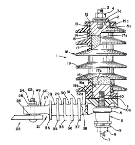
FIG. 1 depicts a surge arrester 1 that in-
cludes a conventional clamping device 2 and threaded
nut 4 for connecting the arrester 1 to an outdoor
electric power distribution system. A ground lead
disconnector 6 includes a clamping device 9 and
threaded nut 8 for connecting a metallic wire to ground
or earth. The body 18 of the arrester, the disconnec-
tor 6 and the insulative arrester bracket 21 are inter-
connected firmly together by means of a threaded con-
ductive stud 10. The arrester 1 is shown mounted to
a portion of a conventional metallic bracket 22 that
includes a carriage bolt 23 that extends through the
insulative bracket 21, a threaded nut 24, a helical
spring lockwasher 25 and an external tooth lockwasher
26. When the surge arrester 1 is placed into service
to protect an outdoor electric power distribution
system, it is mounted firmly to the bracket 22 by the
tightening of the nut 24. The metallic bracket 22
may be electrically grounded by conventional means,
not shown; and a ground wire, not shown, will be con-
nected in the clamp 9. One end of a conductive wire,
not shown, will be connected in the clamp 2 and its
other end to the high voltage wires of the electric
power system.
The body 18 of the arrester 1 includes an
arrester element 13 enclosed within a polymeric
weathershed housing 19. Arrester element 13 includes
metallic spacers 15, 16 and metal oxide varistor ele-
ment 17, which may consist of one or more varistorblocks disposed between and in electrical series con-
tact with the metallic spacers 15, 16. The flat series
contact surfaces, e.g., 17a and 17b, as well as similar
flat series contact surfaces that may exist between
varistor blocks forming varistor element 17, may be
bonded together by soldering or by the use of a conduc-
tive cement, such as a mixture of silver and epoxy,
_ -8- 1 33 4 9 8 9 J-275
as is known in the art. The arrester element 13 may
also include a relatively rigid insulative tube or
wrapping 14, firmly attached to the spacers 15, 16
and retaining the spacers 15, 16 and the varistor
element 17 together in series electrical contact.
The spacers 15, 16 are centrally threaded
to receive and engage the threads of the threaded
studs 3, 10, which pass through central holes of the
metallic discs 11, 12.
During assembly of the arrester 1, a first
layer of adhesive, not shown, is placed between the
metallic disc 12 and the adjacent flat end surfaces,
namely, l9a of the housing 19 and 15a of the spacer
15. Similarly, a second layer of adhesive is placed
between the metallic disc ll and the end surface l9b
of the housing 19 and of the end surface 16a of the
spacer 16. A third layer of adhesive is placed between
the disc 11 and the adjacent flat surface of the insu-
lative bracket 21. The task of applying the adhesive
is relatively simple, since all of the surfaces to
which the adhesive is to be applied are end surfaces,
fully exposed prior to assembly of the surfaces to-
gether. The adhesive may be PLIOBOND #20, made by
the Goodyear Tire & Rubber Co., or another suitable
adhesive.
The polymeric housing 19 may also be elasto-
meric, made of EPDM rubber, for example. It is made
longer in length than is the arrester element 13, by
a predetermined amount; just as it is in prior art
arresters where silicone grease has been used to main-
tain an atmosphere excluding interface at the end
surfaces of an elastomeric housing as well as along
the entire internal bore of the housing. However,
adhesive need not be applied to the bore of the housing
19, nor along the peripheral surface of the arrester
element 13, but merely at the end surfaces referred
to above. Whether the adhesive is applied as a wafer
_ 9 1 ~ 3 g 9 8 9 J 275
cut to the shape of the opposing ends to be bonded,
or is spread or painted on, or is applied as a con-
tinuous bead or line, it is advantageous that the
elastomeric housing be as long, and preferably longer,
than the arrester element. Compression of the elasto-
meric housing then assures that the adhesive will
then bond to the entire end surface of the housing
and to the opposing flat surface to be bonded.
PLIOBOND ~20 is readily applied as a continuous bead
which spreads to fully cover the housing end when
compressed, and it cures at room temperature, though
elevated temperature may be used. For wafers, elevated
temperatures are usually required.
It is to be understood that any of the oppos-
ing flat surfaces that are to be bonded need only be
substantially flat; this is, adequately flat so that
the compression of the housing 19 will cause its end
surfaces l9a, l9b to adequately conform to an opposing
substantially flat surface to form a moisture excluding
seal when bonded. As such, either or both of the
opposing flat surfaces to be bonded may include con-
centric annular grooves or bosses and still be con-
sidered as being substantially flat.
Thus, when the adhesive has been appropriate-
ly applied in a manner as described above, and when
the threaded stud 3, which includes a central flange
portion 3a, and the threaded stud 10, which includes
an end flange 10a, are screwed into the spacers 15,
16, the flange 3a will bear against the disc 12, which,
in turn, through the adhesive, will bear against the
housing end surface l9a and finally against the adja-
cent end surface 15a of the spacer 15. Similarly the
flange 10a will bear against the adjacent portion of
the insulative bracket 21, and the insulative bracket
3 21 will in turn, through the adhesive, bear against
the disc 11, which in turn, through the adhesive,
will bear against the housing end surface 19b and
-lO- 133~9~9 J-275
against the adjacent end surface 16a of the spacer
16. When the threaded studs 3, 10 have been fully
tightened, the housing 19 will be compressed to the
same length as the arrester element 13. The force
then exerted by the housing 19 will assure that the
adhesive at the end surfaces l9a and l9b has been
spread into a thin continuous layer, and that the
adhesive layer will not be disturbed during the time
required for the adhesive to set up and bond the hous-
ing surfaces l9a, l9b to the respective discs 11 and12. When all three layers of adhesive have set up to
bond their respective surfaces, the arrester body 18
will be permanently sealed against the ingress of
moisture and permanently bonded to the insulative
bracket 21. Thus, when torque is applied to the nuts
4, 8, to connect the arrester 1 to a high voltage
electrical system and to a ground wire, respectively,
the torque thereby transmitted will not cause the
arrester body 18 to be rotated with respect to the
insulative bracket 21, as may occur when the body 18
is not bonded or otherwise locked to the insulative
bracket 21.
In another embodiment, the arrester 1 of
FIG. 1 may be assembled without inclusion of the metal-
lic disc 11. In this instance, the third layer of
adhesive would also be deleted, the second layer of
adhesive therefore bonding the housing end surfacel9b, and the end surface 16a of the spacer 16, directly
to the adjacent surface of the insulative bracket 21.
When the arrester 1 is electrically connected
in service, the disc 12, electrically connected to
the clamp 2, is energized at high voltage. The disc
11, in contact with the threaded stud 10 and metallic
cup or cap 5, are all at near ground or earth poten-
tial, as is the conductive metallic bracket 22. There-
fore, little or no voltage is impressed across or
along the insulative arrester bracket 21, between the
-- -ll- 1334989 J-275
disc 11 and the metallic bracket 22. It is well known
and understood that varistor block or blocks 17 within
the arrester body 18 may eventually become damaged,
causing the disconnector 6 to automatically separate
the clamp 9, and the attached ground wire, from the
arrester 1, thereby causing the metal disc 11, together
with the metallic cap 5 to which the flange lOa is
firmly attached, to become energized at high voltage.
The disc 11 may remain energized at high voltage until
the damaged arrester 1 is replaced, or until the insu-
lative bracket 21 itself is unable to withstand the
high voltage, flashes over electrically from the ener-
gized disc 11 to the grounded metallic bracket 22,
and causes an outage of the electrical system.
When the interconnected spacer 16, the disc
11 the stud 10 and the cap 5 are energized at high
voltage, the amount or magnitude of the leakage current
flowing along the creepage distance surfaces, e.g.,
the horizontal surfaces 27-32a, added together with
the horizontal and vertical surfaces of the baffles
33-38 of the insulative bracket 21, will depend on
the amount of the moisture and contaminants deposited
on those surfaces. In general, leakage current in-
creases with increased moisture and contaminants,
e.g., rain water, dust, dirt, salts, etc., and electri-
cal flashover is more likely to occur with increased
leakage current.
The manner in which the insulative bracket
21 has been improved to reduce its weight and cost
and to reduce the amount of moisture or liquid and
contaminants deposited along its creepage path or
leakage distance is best explained with respect to
FIGS. 2 and 3.
In FIGS. 1-7, the same numbers have been
used to identify the same portions of the insulative
bracket 21 and of the metallic bracket 22.
- -12- 1334989 J-275
FIG. 2 illustrates a preferred embodiment
of the present invention, wherein a mass of insulative
material has been molded to form insulative bracket
21 which includes end portions 39, 40 and baffles 33-
38. Also included are the horizontal surfaces 28-32
and 28a-32a, each of which is less than one quarter
as wide as the end portions 39, 40, since their width
is interrupted by the width of the included apertures
41-45.
The apertures 41-45 reduce the mass of the
insulative material required to form the insulative
bracket 21, thereby reducing the weight and cost of
bracket 21. Further, liquids, including rain; and
contaminants such as airborne dirt; can readily drain
or fall entirely through the apertures 41-45, thus
reducing the amount of liquid, moisture or contaminants
that will remain on the insulative bracket 21. As a
consequence, the creepage path can dry quickly, leakage
current flow through the moisture and contaminants is
reduced; and the probability that the bracket 21 will
flashover and cause an electrical outage is reduced.
FIG. 3 depicts the baffle 35 that is also
typical of the baffles 33, 34, 36 and 37, all of which
have been necked down at their centers to even further
reduce the amount and cost of the mass of insulative
material used to form the insulative bracket 21. The
surfaces 30, 30a are the top surfaces of the stringers
46, 47 that may be construed as extending from and
between the end portions 39, 40. The stringers 46,
47, the baffles 33-38 and the end portions 39, 40 are
all rigidly interconnected as one single mass of molded
insulative material, a fiberglass reinforced polyester,
for example.
In FIG. 3, the baffle 35 may also be con-
strued as having been formed of three parts, i.e.,
one baffle formed around stringer 46, a second baffle
formed around stringer 47, and with the two separate
~_ -13- 1 33~98~ 275
baffles being aligned for interconnection by the necked
down portion 48 of baffle 35, thereby forming the
single baffle 35. This construction increases the
rigidity and strength of the insulative bracket 21,
particularly with all baffles 33-37 being formed in
this manner as single baffles, each enclosing both
stringers 46, 47.
As shown in FIG. 1, when the nut 24 has
been tightened on the bolt 23 to compress the helical
spring lockwasher 25 as shown, the lockwasher 25 res-
trains the nut from vibrating loose while the teeth
of the external tooth lockwasher 26 bite into the
adjacent surfaces of the metallic bracket 22 and the
insulative bracket 21 to prevent rotation of the
bracket 21 around the bolt 23. The configuration and
function of the convexity 49 are hereinunder explained
with reference to FIG. 7.
FIG. 4 is a detailed enlargement of the
portion of the prior art insulating base or bracket
depicted on the aforementioned Ohio Brass Instruction
Sheet No. 17-5113, whereon the recommended tightening
torque for nut 24 is shown as 40 ft-lbs.
The concavities 51, 52 of FIG. 4 are shown,
without written description, on the aforementioned
Sheet No. 17-5113. Each concavity 51, 52 defines a
flat surface 51a, 52a at opposing ends of bolt hole
53. On FIG. 4, lockwasher 24 is shown fully compressed
against the flat surface 51a. The teeth of lockwasher
26 are shown at least partially embedded or biting
into the surface 54 of the partially shown insulative
bracket 55, as it might be with 40 ft-lbs of torque
applied to the nut 24.
FIG. 5 is the same as FIG. 4 except that
the nut 24 has been tightened beyond 40 ft-lbs to
further embed the teeth of lockwasher 26 into the
surface 54, and the insulative material forming the
bracket 55 has been cracked, crushed and displaced
_ -14- 133~989 J-275
into the upper portion of the bolt hole 53 and into
the threads of the bolt 23, as depicted by the dashed
lines at 53a. When the nut 24 is then further
tightened, the wedgelike form of the crushed material
53a can cause radial cracks to then form and extend
through the insulative material from the bolt hole
53. This weakens the bracket and renders it non-
reusable, since any attempt to remove the bracket 55
from the bolt 23 requires the removal of the crushed
material 53a that extends into the threads of the
bolt 23. The full embedment of the teeth of the lock-
washer 26 tends to exacerbate the cracking, as evi-
denced by cracks that have been found extending in
line with the teeth of the lockwasher 26.
FIG. 6 depicts the portion 40 of insulative
bracket 21 shown in FIGS . 1 and 2, except that the
convexity 49 together with the concavity 50 have been
deleted. Instead, in accordance with another embodi-
ment of the invention, a radiused surface 56 joins
the flat surface 27 and the bore surface 53 to form
the concavity 57. The concavity 57 causes the washer
25, when compressed against the insulative bracket 21
by the tightening of threaded nut 24, to contact the
insulative bracket 21 only at contact surfaces that
are nearest or adjacent the outer diameter of the
washer 25. As a result, the crushing of the insulative
material surrounding the bolt hole 53, as explained
hereinabove with respect to FIG. 5, has been allevi-
ated, and greater torque may be applied to the nut 24
before crushing or cracking of- the insulative material
surrounding the bolt hole 53 may occur.
While the concavity 57 alleviates the crack-
ing of the insulative bracket 21 that is due to com-
pressing of the washer 25 against the bracket 21, the
cracking due to penetration of the surface 54 by the
teeth of the lockwasher 26 is not alleviated. Such
alleviation is achieved by the preferred embodiment
-15- 13~989 J-275
of the invention as depicted in FIG. 1, and in greater
detail in FIG. 7. Here the insulative bracket 21
includes annular convexities or bosses 49, 49a that
define annular concavities 50, 50a formed as a counter-
sink at the predetermined angle A. The convexities
49, 49a and the defined or surrounded concavities 50,
50a are formed substantially concentrically to bolt
hole 53. The height of the convexities 49, 49a have
been chosen so as to limit the penetration of the
teeth of the lockwasher 26 into the surface 54 to
approximately one-half of the penetration that can
occur against the flat surface -54 as shown in FIG. 5.
Any further penetration of the teeth of washer 26
into the surfce 54, FIG. 7, is prevented when the
central flat portion of the metallic lockwasher 26
impacts the convexity 49a as the nut 24 is tightened.
Because of large variations in the actual
configurations of washers, i.e., lockwasher 25, due
to material thicknesses, forming methods, and corrosion
protective coatings of washers, a chamfer angle A of
4 to 8 decrees has been found to be most advantageous.
The provision of convexities 49, 49a so as
to form concavities 50, 50a has been found to raise
the resistance to the cracking of insulative surge
arrester brackets, the cracking being due to the com-
pression of a flat washer or a helical spring washer
against one side of an insulative bracket as well as
that due to the compression of an external tooth lock-
washer against an opposing side.
While certain advantageous embodiments have
been chosen to illustrate the invention, it will be
understood by those skilled in the art that any embodi-
ment that includes an annular convexity or concavity
or spacing means substantially concentric to a bolt
hole through an arrester insulative bracket is con-
sidered to be within the teachings of the invention
if it causes an insulative bracket to contact a washer
` ~ -16- 1 3 3 ~ g 8 9J-275`'
- surface at surfaces substantially adjacent the outer
diameter of that washer surface rather than at surfaces
substantially adjacent the inner diameter of that
washer surface, when that washer surface is being
compressed against the insulative bracket by the
tightening of a threaded means. When the tightening
has been properly completed, it is to be understood
that the insulative material forming the bracket and
the washer surface itself, may have been mechanically
deformed during the tightening, without deleterious
efEect, so that contact between the washer surface
and the bracket may then also exist at the surfaces
substantially adjacent the inner diameter of the washer
surface.
Obviously, many modifications and variations
of the present invention are possible in light of the
above teachings. Thus, it is to be understood, that,
within the scope of the appended claims, the invention
may be practiced otherwise than as specifically des-
cribed above.